EP0105013B1 - Hydraulisches System und seine Komponenten - Google Patents
Hydraulisches System und seine Komponenten Download PDFInfo
- Publication number
- EP0105013B1 EP0105013B1 EP83450012A EP83450012A EP0105013B1 EP 0105013 B1 EP0105013 B1 EP 0105013B1 EP 83450012 A EP83450012 A EP 83450012A EP 83450012 A EP83450012 A EP 83450012A EP 0105013 B1 EP0105013 B1 EP 0105013B1
- Authority
- EP
- European Patent Office
- Prior art keywords
- cam
- fluid
- membrane
- outlet
- movement
- Prior art date
- Legal status (The legal status is an assumption and is not a legal conclusion. Google has not performed a legal analysis and makes no representation as to the accuracy of the status listed.)
- Expired
Links
- 239000012530 fluid Substances 0.000 claims abstract description 57
- 239000012528 membrane Substances 0.000 claims abstract description 42
- 230000007246 mechanism Effects 0.000 claims abstract description 22
- 238000007789 sealing Methods 0.000 claims description 3
- 230000002262 irrigation Effects 0.000 description 13
- 238000003973 irrigation Methods 0.000 description 13
- 239000007921 spray Substances 0.000 description 9
- XLYOFNOQVPJJNP-UHFFFAOYSA-N water Substances O XLYOFNOQVPJJNP-UHFFFAOYSA-N 0.000 description 9
- 230000010355 oscillation Effects 0.000 description 5
- 230000000694 effects Effects 0.000 description 4
- 239000007788 liquid Substances 0.000 description 4
- 241001417494 Sciaenidae Species 0.000 description 3
- 239000012535 impurity Substances 0.000 description 3
- 230000009471 action Effects 0.000 description 2
- 238000006073 displacement reaction Methods 0.000 description 2
- 230000004044 response Effects 0.000 description 2
- 238000005507 spraying Methods 0.000 description 2
- 239000011324 bead Substances 0.000 description 1
- 230000005540 biological transmission Effects 0.000 description 1
- 230000000903 blocking effect Effects 0.000 description 1
- 239000000470 constituent Substances 0.000 description 1
- 230000001066 destructive effect Effects 0.000 description 1
- 210000004907 gland Anatomy 0.000 description 1
- 239000003621 irrigation water Substances 0.000 description 1
- 238000004519 manufacturing process Methods 0.000 description 1
- 239000000463 material Substances 0.000 description 1
- 210000000056 organ Anatomy 0.000 description 1
- 230000002093 peripheral effect Effects 0.000 description 1
- 230000007704 transition Effects 0.000 description 1
Images



Classifications
-
- A—HUMAN NECESSITIES
- A01—AGRICULTURE; FORESTRY; ANIMAL HUSBANDRY; HUNTING; TRAPPING; FISHING
- A01G—HORTICULTURE; CULTIVATION OF VEGETABLES, FLOWERS, RICE, FRUIT, VINES, HOPS OR SEAWEED; FORESTRY; WATERING
- A01G25/00—Watering gardens, fields, sports grounds or the like
- A01G25/09—Watering arrangements making use of movable installations on wheels or the like
- A01G25/095—Watering arrangements making use of movable installations on wheels or the like winch-driven
Definitions
- the invention described in detail in the present application relates to devices which are intended to be used in connection with irrigation systems and relates to the combination of such devices with each other and with such irrigation systems, but it also has for other applications in which an intermittent pressurized fluid is required, for example to obtain an oscillating movement of an organ.
- drum type irrigation systems a large drum carries a length of hose that goes up to a spray cart.
- the spray cart is pulled from the drum to extend the hose.
- the spray nozzle irrigates the field while the drum slowly rotates to retract and wind the hose and pull the spray cart toward the drum.
- the drum rotation mechanism comprises an expandable chamber device, such as a piston or a bellows, which controls an oscillating member, which, when it moves in one direction causes the drum to rotate and, when it moves in the opposite direction has no effect on the rotation of the drum.
- an expandable chamber device such as a piston or a bellows
- the oscillating member can be movable in a linear stroke or in an arc.
- the intermittent pressurized fluid is supplied to the expandable chamber device by a hydraulic system which includes an actuating mechanism and valves.
- an eccentric lever is connected to the stem of a three-way valve which supplies the fluid directly to a bellows which controls a member connected to it.
- the water used in the irrigation system usually contains a significant amount of impurities and it has been found that these impurities have a destructive effect on the components of the valves, which leads to leaks and unreliability . Likewise, the material force to move the valve from one position to another is substantial.
- An object of the present invention is to provide a hydraulic system for dispensing a pressurized fluid intermittently which is simple, inexpensive to manufacture and more reliable than existing systems, in particular when it is used for a fluid which contains impurities. .
- the system according to the present invention requires less power and allows higher performance when combined with a device with high water pressure.
- Valve system components are less likely to leak, in part because the main three-way valve does not have a gland, and they are more compact due to the lower volume of liquid flowing through the pilot valve which is connected mechanical actuation means.
- the mechanical actuation means is superior to those of the prior art by its simplicity, the absence of eccentric lever and its ability to operate when it is actuated in a relatively short movement.
- the actuation mechanism can be at will and automatically rendered inoperative and when in operation, it is provided with a memory which allows it to maintain its position until it is controlled by the control member. .
- the hydraulic system for supplying pressurized fluid to a hydraulic device comprises:
- a three-way valve comprising a fluid inlet and two outlets, a first outlet for conveying the fluid to the hydraulic device and a second outlet communicating with the open air
- the three-way valve is divided by an elastic membrane into two chambers, a fluid passage chamber and a membrane control chamber by a fluid, the said elastic membrane in a first position allowing communication between the first outlet and the second outlet, this is that is to say the communication of said device with the open air and the closing of the fluid inlet, this closing being ensured by a ball valve controlled by the membrane, and in a second position, under the effect of a controlled pressure on said membrane allowing the closing of the second outlet and the communication between the inlet and the first outlet, that is to say between the inlet and said hydraulic device, in that a dist pilot ripper delivers pressurized fluid to the membrane control chamber, the said distributor having a movable rod between two positions, a first position in which delivery of the fluid to the membrane control chamber is interrupted and a second position according to
- the hydraulic system for supplying pressurized fluid to a hydraulic device is characterized in that said membrane has a configuration in concavo-convex saucer and having the characteristic of elasticity like a spring so that it returns by itself to its first position in the absence of a force in opposite direction likely to deform it in its second position .
- the hydraulic system according to the invention for supplying a pressurized fluid is adaptable and can be used with a drum and flexible hose irrigation system of the known type represented in FIG. 1.
- This system comprises a large rotary drum 2 which carries a long flexible hose for irrigation water, a part of this hose being represented and referenced by the mention 4.
- the pipe 4 is connected to a sprinkler carriage 6 which has a spray nozzle 8 and which is carried mobile by wheels 10.
- the spray cart 6 is first pulled from the drum, causing the tube to extend from the drum and positioning the spray cart 6 at a starting point relatively distant from the drum 2.
- the water supply is turned on so that the spray nozzle begins to irrigate the field.
- the drum is rotated in the direction of arrow 12 to wind the pipe 4 again on the drum 2 and it drives the spray trolley through the field.
- the mechanism for rotating the drum has an oscillating arm 14 which moves at a reduced angle.
- the outer end of the arm 14 operatively connected to a transmission, chain or the like, which drives the drum 2 in rotation.
- the swinging movement of the arm is produced by a single action hydraulic piston 18 which acts in the opposite direction to a return spring.
- the piston 18 is only one type of device adaptable to an expandable chamber among others such as double-action pistons, bellows, cylinders, etc.
- the piston 18 is driven by water or any other hydraulic fluid and it communicates the oscillation movement to the arm 14, which drives the drum and pulls the pipe 4 and the carriage 6 towards the drum during the spraying.
- the arm 14 is functionally connected to a rod 82 for controlling the cam and transmits an alternating movement to the said rod which is also functionally connected to a cam 90 shown in FIGS. 2, 3 and 4.
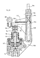
- FIG. 2 A preferred hydraulic system is shown in FIG. 2. It comprises a three-way valve 20 with an outlet 22 which supplies hydraulic pressure to the piston 18, a pilot distributor 24 which gives controlled pressure to the main valve 20, and a mechanism for actuation 26 which actuates the dispenser.
- An irrigation pump 28 supplies pressurized water to a main conduit 30 connected by the branches 32, 34 and 36 to the distributor 24, to the valve 20 and to the pipe 4.
- the pilot distributor 24 consists of a cover 38 and a main body 40 which is provided with an inlet duct 42, a main chamber 44 receiving the liquid from the inlet duct 42 and a outlet opening ( Figure 3) to conduct the pressurized fluid from the distributor 24 to the main valve 20.
- a counterbore 48 which receives two inserts 50 and 52.
- the upper insert 50 presses against a blocking piece 54 to retain and lock the lower insert 52 in position.
- the lower insert 52 is provided with a central bore 56 and radial conduits 58 which lead to a peripheral channel 60 in communication with an outside flow conduit 62.
- the pilot distributor 24 has a rod 64 which is shown in the position it occupies during its downward stroke.
- the rod comprises a cylindrical barrel 66, a frustoconical transition section 68 and a needle 69.
- the cylindrical barrel extends between a pair of spaced sealing washers 70 and 72 which define between them in combination with the lower insert a discharge chamber 73.
- a discharge chamber 73 Located under the main chamber 44 is formed an inlet duct with a conical seat 74.
- a sphere 76 in the duct 42 can be blocked in closing against the seat 74 to prevent the liquid from entering the main chamber 44.
- the rod 64 is normally prestressed by a spring 78 to an upper position in which the cylindrical surface of the barrel 66 is not in contact with the lower sealing washer 72, which allows communication between the evacuation chamber 73 and master bedroom 44.
- a downward movement of the rod 64 compresses the spring 78 and brings the cylindrical surface of the rod into closure contact with the washer 72 so as to interrupt the communication between the chambers 44 and 73 as shown in FIG. 2. Additional downward movement of the rod causes the sphere to move downward through the needle, away from the seat 74 so that the water from the inlet duct 42 will flow into the main chamber 44 and through the outlet 46 in a conduit 80.
- the pilot distributor when used with a drum irrigation device as shown in fig. 1, is actuated in response to the movement of the arm 14.
- This rod (fig. 2) comprises a pair of spaced apart rings 84 and 86 which are fixed on the same longitudinal axis by screws or the like.
- the rod passes through a ring 88 which is fixed with articulation to an oscillating cam 90.
- a cam surface 92 on the lower side of the cam 90 cooperates with a roller 94.
- the roller is rotatably attached to the free outer end of a lever arm 96 whose opposite end is mounted with articulation at 98 to a fixed stock 100 of the main body of the valve.
- the movement of the cam 90 can be a rectilinear oscillation movement, it is preferable for it to follow an oscillation in an arc of a circle.
- This support comprises an upwardly directed barrel 104 fixed in a non-rotatable manner to a protrusion 106 of the body of the dispenser.
- the cam 90 has a portion 108 forming a bearing which overlaps the barrel 104 and rotates relative to the latter, depending on whether the cam is guided back and forth by the rod 82.
- the cam 90 cooperates frictionally with a friction member, especially a lining 110 on the lower surface of a shoe 112.
- the shoe 112 is connected in a non-rotatable manner to the shaft 104 so that the cam 90 moves relative to the lining 110 of the shoe 112.
- the cam 90 can be released so that it can move upwards in a direction which is substantially parallel to the movement of the follower roller 94.
- This release can be done by allowing the shoe 112 to be freely movable upwards so that the pad 108 of the cam can also move upwards during its rotational movement on the barrel.
- the cam 90 is held in an axially fixed position on the barrel 104 by the shoe 112 which is held down by an eccentric cam 114.
- the cam 114 has a handle 116 and is pivotally connected to the upper end of the barrel 104 by an axis 118.
- the irrigation system may be provided with a device (triangle system)), not shown, which will automatically order the handle 116 to turn the eccentric 114 in a position where it is no longer supported on the skate.
- a device triangle system
- Such an automatic disengaging mechanism can be used to disengage the rotation mechanism of the drum, as for example the spraying carriage 6 has been pulled back to a position adjacent to the drum.
- valve 20 is used to supply the actuating fluid to an expandable chamber device 18 in an irrigation apparatus.
- the opening and closing of this valve is in response to a controlled pressure from the distributor 24.
- the valve housing 20 comprises a main body 120 and a cover 122.
- a membrane 124 separates the interior of the housing between a control chamber of the membrane by a fluid 126 and a lower chamber for passage of the fluid 136.
- the membrane control chamber 126 is connected to the fluid control line 80 of the pilot valve 24 so as to receive a controlled pressure therefrom.
- the membrane 124 is shown in its second position mentioned above or working position, this position being taken when the membrane control chamber with a fluid 126 is supplied with fluid by the pipe 80.
- the first position, or rest position, of the membrane is shown in broken lines.
- the valve has an inlet conduit 144 which receives water from the main pump 28 of the irrigation system, a first outlet conduit 22 which delivers water to the device to the expandable chamber and a second outlet conduit 152 which allows water to escape from the expandable chamber device to an open air outlet.
- the membrane 124 has a relatively thick circular central portion 130, a thinner annular portion 132 which surrounds and is connected to the central portion and a circular bead 134 which is housed in a circular groove of the housing.
- the membrane has the shape of a concave-convex saucer and has the characteristic of a spring in that it simultaneously resumes its first position in the absence of sufficient opposite force to deform it in its second position.
- the lower chamber 136 for passage of the fluid has an inlet 138, an outlet 22 which leads to the cylinder 18 for rotation of the drum and a second outlet 140 which is surrounded by a circular seat 142.
- An inlet duct 144 leads to the inlet 138, it comprises a sphere 146 housed near a conical inlet seat 148.
- the sphere 146 comes into locking against the seat 148 under the action of the pressure of the fluid in conduit 144.
- a movable needle 150 Directly above and centered on the sphere is disposed a movable needle 150, the end of which comes into contact with the lower surface of the membrane 124.
- the length of the needle is such that when the membrane is in its upper position, the needle imposes no downward force on the sphere 146 except under the effect of its own weight.
- the needle 150 transmits the movement of the membrane to the sphere 146 by moving it away from the seat 148 and allowing the pressurized fluid to flow from the inlet duct 144 towards the inlet 138 of the chamber 136.
- the membrane 124 comes into contact to close the seat 142 so that no pressure can be lost through the evacuation orifice 140.
- the membrane is moved from its upper position to its lower position by the pressure of the pipe 80.
- the upward movement of the diaphragm also separates it from the seat 142 which surrounds the discharge outlet 140, so that the pressure of the fluid can be discharged in the open air through the outlet duct 152.
- the invention can receive arrangements and variants not completely described in the present description but in the application of fluid under intermittent pressure within the scope of the claims below.
Landscapes
- Engineering & Computer Science (AREA)
- Water Supply & Treatment (AREA)
- Life Sciences & Earth Sciences (AREA)
- Environmental Sciences (AREA)
- Catching Or Destruction (AREA)
- Fluid-Pressure Circuits (AREA)
- Reciprocating Pumps (AREA)
Claims (9)
Priority Applications (1)
| Application Number | Priority Date | Filing Date | Title |
|---|---|---|---|
| AT83450012T ATE40259T1 (de) | 1982-05-12 | 1983-05-11 | Hydraulisches system und seine komponenten. |
Applications Claiming Priority (2)
| Application Number | Priority Date | Filing Date | Title |
|---|---|---|---|
| US37751282A | 1982-05-12 | 1982-05-12 | |
| US377512 | 1982-05-12 |
Publications (3)
| Publication Number | Publication Date |
|---|---|
| EP0105013A2 EP0105013A2 (de) | 1984-04-04 |
| EP0105013A3 EP0105013A3 (en) | 1985-10-02 |
| EP0105013B1 true EP0105013B1 (de) | 1989-01-25 |
Family
ID=23489402
Family Applications (1)
| Application Number | Title | Priority Date | Filing Date |
|---|---|---|---|
| EP83450012A Expired EP0105013B1 (de) | 1982-05-12 | 1983-05-11 | Hydraulisches System und seine Komponenten |
Country Status (3)
| Country | Link |
|---|---|
| EP (1) | EP0105013B1 (de) |
| AT (1) | ATE40259T1 (de) |
| DE (1) | DE3379026D1 (de) |
Families Citing this family (1)
| Publication number | Priority date | Publication date | Assignee | Title |
|---|---|---|---|---|
| CN111387022A (zh) * | 2020-05-08 | 2020-07-10 | 宋晓莉 | 一种计量式农业增压灌溉装置 |
Family Cites Families (5)
| Publication number | Priority date | Publication date | Assignee | Title |
|---|---|---|---|---|
| US3856046A (en) * | 1972-10-17 | 1974-12-24 | Tool Instr Ass Inc | Valve |
| FR2312699A1 (fr) * | 1975-05-30 | 1976-12-24 | Irrifrance | Vanne hydraulique a trois voies et applications avec des liquides charges d'impuretes |
| DE2651081A1 (de) * | 1976-11-09 | 1978-05-18 | Juergen Luehr | Beregnungsanlage |
| FR2393527A1 (fr) * | 1977-06-10 | 1979-01-05 | Irrifrance | Appareil d'arrosage a tambour entraine par l'eau d'arrosage |
| FR2500260A1 (fr) * | 1981-02-26 | 1982-08-27 | Ferrandez Bernard | Appareil pour l'irrigation du type enrouleur a bobine motorisee et dispositif de motorisation |
-
1983
- 1983-05-11 EP EP83450012A patent/EP0105013B1/de not_active Expired
- 1983-05-11 DE DE8383450012T patent/DE3379026D1/de not_active Expired
- 1983-05-11 AT AT83450012T patent/ATE40259T1/de not_active IP Right Cessation
Also Published As
| Publication number | Publication date |
|---|---|
| EP0105013A3 (en) | 1985-10-02 |
| EP0105013A2 (de) | 1984-04-04 |
| DE3379026D1 (en) | 1989-03-02 |
| ATE40259T1 (de) | 1989-02-15 |
Similar Documents
| Publication | Publication Date | Title |
|---|---|---|
| FR2565130A1 (fr) | Pulverisateur manuel et pompe a diaphragme pour pulverisateur | |
| EP2344726A1 (de) | System zur steuerung einer anlage mit variabler geometrie für einen turbinenmotor, im besonderen mithilfe von winkelhebeln | |
| EP0883731B1 (de) | Kernbohrwerkzeug | |
| EP1070212B1 (de) | Integrierter entnahmeregler für eine dampfturbine | |
| EP1364890B1 (de) | Vorrichtung für die plötzliche Druckluftablade | |
| EP1364891B1 (de) | Belüftungsvorrichtung durch plötzliches Ablassen von Druckluft mit einem verbesserten Auswerferrohr | |
| FR2557665A1 (fr) | Ensemble a vanne et dispositif pour nettoyer une surface immergee dans un liquide, mettant en oeuvre ladite vanne | |
| FR1464389A (fr) | Distributeur composé d'une buse et d'une valve combinées | |
| EP0105013A2 (de) | Hydraulisches System und seine Komponenten | |
| FR2724958A1 (fr) | Installation de distribution d'eau pour reservoir de chasse de toilettes sanitaires | |
| FR2562965A1 (fr) | Soupape d'inversion, pour commander notamment un verin hydraulique | |
| FR2618868A1 (fr) | Dispositif formant detendeur de regulation automatique de pression d'un fluide gazeux | |
| EP0153253B1 (de) | Hydraulisches Hochdruckwegeventil mit mechanisch steuerbarem Auslassventil | |
| FR2798650A1 (fr) | Dispositif de distribution destine a equiper un recipient | |
| FR2579936A1 (de) | ||
| EP0230822B1 (de) | Durchflussregelbarer Flüssigkeitskreislauf | |
| EP0761280B1 (de) | System zum Reinigen rohrförmiger Filterelemente | |
| FR2614172A1 (fr) | Dispositif de commande pour un enrouleur d'appareil d'arrosage. | |
| BE498076A (de) | ||
| FR2699367A1 (fr) | Dispositif de commande pour le pivotement autour de son axe de rotation d'une charrue à double brabant. | |
| FR2616509A1 (fr) | Clapet a commande pneumatique et accumulateur hydropneumatique equipe de ce clapet | |
| FR2814510A1 (fr) | Distributeur hydraulique, circuit hydraulique comprenant un tel distributeur pour la commande des mouvements de deux verins double effet | |
| FR2503312A1 (fr) | Soupape de trop-plein | |
| FR2926231A1 (fr) | Applicateur de liquide. | |
| FR2473650A1 (fr) | Dispositif regulateur de debit pour la commande d'un verin double effet |
Legal Events
| Date | Code | Title | Description |
|---|---|---|---|
| PUAI | Public reference made under article 153(3) epc to a published international application that has entered the european phase |
Free format text: ORIGINAL CODE: 0009012 |
|
| AK | Designated contracting states |
Designated state(s): AT BE CH DE FR GB IT LI LU NL SE |
|
| 17P | Request for examination filed |
Effective date: 19840712 |
|
| PUAL | Search report despatched |
Free format text: ORIGINAL CODE: 0009013 |
|
| AK | Designated contracting states |
Designated state(s): AT BE CH DE FR GB IT LI LU NL SE |
|
| ITCL | It: translation for ep claims filed |
Representative=s name: STUDIO CORRADINI |
|
| ITPR | It: changes in ownership of a european patent |
Owner name: CONCESSIONE DI LICENZA ESCLUSIVA;IRRIMEC ITALIANA |
|
| 17Q | First examination report despatched |
Effective date: 19861030 |
|
| D17Q | First examination report despatched (deleted) | ||
| ITF | It: translation for a ep patent filed | ||
| GRAA | (expected) grant |
Free format text: ORIGINAL CODE: 0009210 |
|
| AK | Designated contracting states |
Kind code of ref document: B1 Designated state(s): AT BE CH DE FR GB IT LI LU NL SE |
|
| PG25 | Lapsed in a contracting state [announced via postgrant information from national office to epo] |
Ref country code: GB Free format text: LAPSE BECAUSE OF NON-PAYMENT OF DUE FEES Effective date: 19890125 Ref country code: NL Effective date: 19890125 Ref country code: SE Effective date: 19890125 Ref country code: AT Effective date: 19890125 |
|
| REF | Corresponds to: |
Ref document number: 40259 Country of ref document: AT Date of ref document: 19890215 Kind code of ref document: T |
|
| REF | Corresponds to: |
Ref document number: 3379026 Country of ref document: DE Date of ref document: 19890302 |
|
| PG25 | Lapsed in a contracting state [announced via postgrant information from national office to epo] |
Ref country code: BE Effective date: 19890531 Ref country code: LU Free format text: LAPSE BECAUSE OF NON-PAYMENT OF DUE FEES Effective date: 19890531 Ref country code: CH Effective date: 19890531 Ref country code: LI Effective date: 19890531 |
|
| NLV1 | Nl: lapsed or annulled due to failure to fulfill the requirements of art. 29p and 29m of the patents act | ||
| GBV | Gb: ep patent (uk) treated as always having been void in accordance with gb section 77(7)/1977 [no translation filed] | ||
| PLBE | No opposition filed within time limit |
Free format text: ORIGINAL CODE: 0009261 |
|
| STAA | Information on the status of an ep patent application or granted ep patent |
Free format text: STATUS: NO OPPOSITION FILED WITHIN TIME LIMIT |
|
| 26N | No opposition filed | ||
| REG | Reference to a national code |
Ref country code: CH Ref legal event code: AUV Free format text: LE BREVET CI-DESSUS EST TOMBE EN DECHEANCE FAUTE DE PAIEMENT, DE LA 7E ANNUITE. Ref country code: CH Ref legal event code: PL |
|
| PG25 | Lapsed in a contracting state [announced via postgrant information from national office to epo] |
Ref country code: DE Effective date: 19900201 |
|
| REG | Reference to a national code |
Ref country code: FR Ref legal event code: ST |
|
| ITTA | It: last paid annual fee | ||
| REG | Reference to a national code |
Ref country code: FR Ref legal event code: AR |
|
| REG | Reference to a national code |
Ref country code: FR Ref legal event code: BR |
|
| PGFP | Annual fee paid to national office [announced via postgrant information from national office to epo] |
Ref country code: FR Payment date: 20010413 Year of fee payment: 19 |
|
| PG25 | Lapsed in a contracting state [announced via postgrant information from national office to epo] |
Ref country code: FR Free format text: LAPSE BECAUSE OF NON-PAYMENT OF DUE FEES Effective date: 20030131 |
|
| REG | Reference to a national code |
Ref country code: FR Ref legal event code: ST |