EP0105037A2 - Vortexreiniger - Google Patents
Vortexreiniger Download PDFInfo
- Publication number
- EP0105037A2 EP0105037A2 EP83850230A EP83850230A EP0105037A2 EP 0105037 A2 EP0105037 A2 EP 0105037A2 EP 83850230 A EP83850230 A EP 83850230A EP 83850230 A EP83850230 A EP 83850230A EP 0105037 A2 EP0105037 A2 EP 0105037A2
- Authority
- EP
- European Patent Office
- Prior art keywords
- chamber
- vortex
- baffle
- suspension
- baffles
- Prior art date
- Legal status (The legal status is an assumption and is not a legal conclusion. Google has not performed a legal analysis and makes no representation as to the accuracy of the status listed.)
- Granted
Links
Images

Classifications
-
- D—TEXTILES; PAPER
- D21—PAPER-MAKING; PRODUCTION OF CELLULOSE
- D21D—TREATMENT OF THE MATERIALS BEFORE PASSING TO THE PAPER-MAKING MACHINE
- D21D5/00—Purification of the pulp suspension by mechanical means; Apparatus therefor
- D21D5/18—Purification of the pulp suspension by mechanical means; Apparatus therefor with the aid of centrifugal force
- D21D5/24—Purification of the pulp suspension by mechanical means; Apparatus therefor with the aid of centrifugal force in cyclones
-
- B—PERFORMING OPERATIONS; TRANSPORTING
- B04—CENTRIFUGAL APPARATUS OR MACHINES FOR CARRYING-OUT PHYSICAL OR CHEMICAL PROCESSES
- B04C—APPARATUS USING FREE VORTEX FLOW, e.g. CYCLONES
- B04C5/00—Apparatus in which the axial direction of the vortex is reversed
- B04C5/08—Vortex chamber constructions
- B04C5/103—Bodies or members, e.g. bulkheads, guides, in the vortex chamber
Definitions
- the present invention relates to a vortex cleaner for separating a fibre-liquid-suspension, and in particular a paper-pulp suspension, into fractions, said vortex cleaner being of the kind well known per se which includes an elongate vortex chamber of circular cross-section which tapers towards one end thereof along part of its length, said chamber having at its wider end a substantially tangentially directed inlet for the suspension to be treated, and an axially directed first outlet for a light fraction of the treated suspension, and having at its narrower end an axially directed second outlet for a heavier fraction of the treated suspension.
- Vortex cleaners of this kind are used to a large extent in the paper pulp industry for cleansing paper-pulp suspensions from such impurities as shives, sand, particles of metal, and also larger impurities, such as staples, paper clips, nails, screws, nuts, stones etc., these latter impurities often being found in paper pulp produced ' from return paper. ,
- the so-called inject when using a vortex cleaner of this kind the suspension to be treated, the so-called inject, is fed at high speeds through the tangential inlet at the wider end of the vortex chamber adjacent the inner surface of the chamber wall, whereupon the input suspension forms a helical vortex flow which moves along the inside of the chamber wall towards the opposite, narrowing end of the chamber.
- the particles in the suspension strive to orientate themselves, so that the coarser and heavier particles, e.g. the impurities contained in a paper-pulp suspension, collect as far as possible out to the chamber wall, while the lighter particles, e.g. the useful fibres contained in the suspension, remain closer to the geometric centre axis of the vortex chamber.
- the vortex flow is subjected to radial compression forces in the narrowing part of the vortex chamber, and as a result thereof that part of the vortex flow located closest to the centre axis of the vortex chamber is caused to turn about and move axially in the opposite direction, in the form of an internal helical vortex flow, which is removed through the axially directed outlet at the wider end of the vortex chamber as a light fraction, the so-called reject, which when cleaning a paper-pulp suspension shall comprise useful fibres.
- pulp-suspension cleansing plants comprise a plurality of vortex-cleaner stages arranged sequentially in cascade. It will be under-stood, however, that the more effectively each cleaner cleanses the suspension treated therein, the smaller the number of cascade-coupled cleaners required, resulting in a lowering of both plant investment and running costs.
- Vortex cleaners of this kind are described, for example, in Swedish Patent Specification 393 644 and U.S. Patent Specification 4 224 145. Vortex cleaners of this design, and in particular those designed in accordance with the U.S.
- Patent Specification have been found to effectively prevent blocking of the vortex-cleaner, without needing to increase the flow of reject or the inject-infeed pressure. Although effective in preventing blockages, however, these vortex cleaners have the disadvantage that the reject contains and undesirably high percentage of useful fibres, and that consequently such cleaners do not have the desired cleaning effect.
- This boundary layer is substantially cylindrical within ⁇ the cylindrical part of the vortex chamber, and has a substantially conical configuration within the conically tapering portion of the chamber.
- the lighter and heavier particles in the suspension are caused to migrate radially through said boundary layer by the action of the centrifugal forces in the vortex flows, so that the heavier impurities collect in the outer vortex flow, while the lighter particles, e.g. the useful fibres, collect in the inner vortex flow.
- the object of the present invention is to provide a vortex cleaner of the initially described kind, in which the aforediscussed problems are reduced, so that blocking of the cleaner is still prevented without needing to increase the magnitude of the reject flow or the inject-feed pressure, while at the same time greatly reducing the amount of useful fibres accompanying the flow of reject from the vortex chamber.
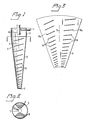
- the exemplary vortex cleaner according to the invention schematically illustrated in the drawings comprises in a manner known per se, an elongate vortex chamber which is generally referenced 1 and which includes a circular- cylindrical part 2 and a part 3 which tapers conically towards one end of the vortex chamber.
- a tangentially directed inlet 4 for the suspension to be treated and also an axially directed accept outlet 6 for a lighter fraction of the treated suspension, the outlet 6 being centrally located relative to the longitudinal axis 5 of the chamber.
- the accept outlet 6 has the form of a so-called vortex-finder pipe, in a conventional manner.
- a corresponding, axially directed reject outlet 7 for a heavier fraction of the treated suspension.
- This reject outlet can be connected, in a conventional manner, to a suitable, conventional reject-discharge means (not shown) for controlling the magnitude of the reject flow.
- the suspension When suspension is fed through the inject inlet 4 at high speed in a tangential direction adjacent the inner surface of the chamber wall, the suspension forms within the vortex chamber a helical vortex flow, which moves towards the narrowing end of the chamber. Under the influence of the centrifugal forces acting in the vortex flow, the particles in the suspension strive to orientate themselves, so that the heavier particles collect in.a layer close to the inside of the wall, this layer being carried by the vortex flow and fed out through the reject opening 7. Because of the tapering shape of the vortex chamber, the major part of the vortex flow will turn within the conical part 3 of the chamber and continue to move as an inner, helical vortex flow in the opposite direction, back to the wider end of the vortex chamber.
- This inner vortex flow which ideally is substantially free of coarse and heavy particles, i.e. from impurities, is fed out through the vortex finder 6.
- a boundary layer in which the axial velocity of the flow is substantially zero.
- the location of this boundary layer 8 is indicated by chain lines.
- the particles in the suspension are carried radially through the boundary layer, so that the heavy and coarse particles, i.e. the impurities, collect nearest the wall of the vortex chamber and are fed out through the reject outlet 7, while the light particles, i.e. the useful fibres, collect in the inner vortex flow and are fed out through the vortex-finder pipe 6.
- the vortex chamber 1 is provided, within its conically tapering part 3, with a plurality of baffles 9 which project radially inwardly from the chamber wall and which are inclined in the flow direction of the helical vortex flow, towards the reject outlet 7.
- the baffles 9 are effective in forcing the impurity-containing suspension layer, located close to the wall of the vortex chamber, to move towards and out through the reject outlet 7, so that no blocking of the vortex cleaner can take place, even though the outflow of reject is kept small and the infeed pressure at the inject inlet 4 is relatively moderate. None of the baffles 9, however, extends continuously over the whole lengt of the conically tapering part of the vortex chamber 1.
- the baffles 9 are so arranged as -to exhibit interruptions, or interspaces, between mutually sequential baffles, in the axial and/or peripheral direction.
- that part of the suspension flow which is located momentarily beneath a baffle 9 and is forced downwardly thereby towards the reject outlet 7 is afforded the possibility, as said suspension leaves the downstream end of the baffle, of flowing freely without being influenced by a baffle, whereby a substantial part of said suspension will have a chance of coming into contact with the boundary layer 8, and there to take part in the aforedescribed fractionating process, so that light particles, i.e. useful fibres, present in said part of said suspension flow are able to pass to the inner vortex flow directed towards the vortex-finder pipe 6, radially inwardly of the boundary layer 8.
- each baffle 9 comprises a flat plate having substantially the shape of a segment of a circle.
- the baffles are attached in an inclined position to the conical wall 3 of the vortex chamber, for example by inserting the baffles into respective slots in the chamber wall and welding the baffles in said slots.
- Each baffle 9 has a length which corresponds substantially to a quarter turn around the circumference of the vortex chamber, and the peripheral distance between the downstream end of given baffle and the upstream end of an immediately following baffle also corresponds substantially to a quarter of the circumference of the vortex chamber.
- the baffles of the exemplary embodiment are so arranged that the downstream end of a given baffle, for example the baffle 9a in Figure 3, is located on substantially the same axial level as the upstream end of the nearest following baffle 9b. It is an advantage that each baffle has a width which decreases towards both the upstream of the baffle and its downstream end, since in this way those parts of the suspension flow located nearest the boundary layer 8 are better able to come into contact with the boundary layer 8.
- baffles 9 can be designed and arranged in several different ways, for example so that between the downstream end of a given baffle and the upstream end of the next immediate baffle there exists an interspace, not only in the peripheral direction but also in the axial direction, or optionally solely in the axial direction.
- Each baffle can also extend over a greater or smaller part of the periphery of the vortex cleaner, and each baffle may be sufficiently long to extend more than a complete turn around the periphery of the vortex cleaner. Neither is it necessary that the baffles are arranged symmetrically.
- baffles in the remaining set may be given a larger length.
Landscapes
- Engineering & Computer Science (AREA)
- Mechanical Engineering (AREA)
- Cyclones (AREA)
- Paper (AREA)
- Separation Of Solids By Using Liquids Or Pneumatic Power (AREA)
- Filters For Electric Vacuum Cleaners (AREA)
- Bipolar Transistors (AREA)
- Transplanting Machines (AREA)
Priority Applications (1)
| Application Number | Priority Date | Filing Date | Title |
|---|---|---|---|
| AT83850230T ATE25270T1 (de) | 1982-09-02 | 1983-08-29 | Vortexreiniger. |
Applications Claiming Priority (2)
| Application Number | Priority Date | Filing Date | Title |
|---|---|---|---|
| SE8205011 | 1982-09-02 | ||
| SE8205011A SE435582B (sv) | 1982-09-02 | 1982-09-02 | Virvelrenare for separering av fiber-vetskesuspensioner, i synnerhet av pappersmassa, i en langstreckt cirkuler virvelkammare |
Publications (3)
| Publication Number | Publication Date |
|---|---|
| EP0105037A2 true EP0105037A2 (de) | 1984-04-04 |
| EP0105037A3 EP0105037A3 (en) | 1984-09-12 |
| EP0105037B1 EP0105037B1 (de) | 1987-01-28 |
Family
ID=20347701
Family Applications (1)
| Application Number | Title | Priority Date | Filing Date |
|---|---|---|---|
| EP83850230A Expired EP0105037B1 (de) | 1982-09-02 | 1983-08-29 | Vortexreiniger |
Country Status (8)
| Country | Link |
|---|---|
| US (1) | US4537314A (de) |
| EP (1) | EP0105037B1 (de) |
| JP (1) | JPS5966592A (de) |
| AT (1) | ATE25270T1 (de) |
| CA (1) | CA1206920A (de) |
| DE (1) | DE3369540D1 (de) |
| FI (1) | FI71790C (de) |
| SE (1) | SE435582B (de) |
Cited By (6)
| Publication number | Priority date | Publication date | Assignee | Title |
|---|---|---|---|---|
| AU629719B2 (en) * | 1989-12-16 | 1992-10-08 | Onoda Cement Co., Ltd. | Straightening instrument and cyclone |
| WO1998047622A1 (en) * | 1997-04-18 | 1998-10-29 | Beloit Technologies, Inc. | Channeling dam for centrifugal cleaner |
| US6036027A (en) * | 1998-01-30 | 2000-03-14 | Beloit Technologies, Inc. | Vibratory cleaner |
| US6109451A (en) * | 1998-11-13 | 2000-08-29 | Grimes; David B. | Through-flow hydrocyclone and three-way cleaner |
| RU2260476C1 (ru) * | 2004-08-13 | 2005-09-20 | Государственное образовательное учреждение высшего профессионального образования Воронежская государственная технологическая академия | Пылеуловитель |
| RU2686177C1 (ru) * | 2018-10-15 | 2019-04-24 | Федеральное государственное бюджетное образовательное учреждение высшего образования "Воронежский государственный университет инженерных технологий" (ФГБОУ ВО "ВГУИТ") | Устройство для пылеулавливания |
Families Citing this family (12)
| Publication number | Priority date | Publication date | Assignee | Title |
|---|---|---|---|---|
| US4647212A (en) * | 1986-03-11 | 1987-03-03 | Act Laboratories, Inc. | Continuous, static mixing apparatus |
| NO320957B1 (no) | 2002-10-02 | 2006-02-20 | Statoil Asa | Separasjonsenhet |
| KR100601058B1 (ko) | 2004-04-01 | 2006-07-19 | 백인우 | 모래 세척 장치 |
| RU2496584C1 (ru) * | 2012-03-06 | 2013-10-27 | Дмитрий Валентинович Каргашилов | Центробежный пылеулавливатель |
| US8997310B2 (en) | 2012-10-12 | 2015-04-07 | Electrolux Home Care Products, Inc. | Vacuum cleaner cyclone with helical cyclone expansion region |
| USD689658S1 (en) | 2012-12-12 | 2013-09-10 | Electrolux Home Care Products, Inc. | Exterior surface of a cyclone receptacle |
| JP2015217326A (ja) * | 2014-05-15 | 2015-12-07 | 吉雄 網本 | 気液分離効率の改善されたサイクロン式気液分離器 |
| WO2018027314A1 (en) | 2016-08-09 | 2018-02-15 | Rodney Allan Bratton | In-line swirl vortex separator |
| CN112122019B (zh) * | 2020-09-02 | 2021-10-15 | 东莞福莱仕智能电子科技有限公司 | 一种旋风分离装置及清洁设备 |
| CN112043202B (zh) * | 2020-09-02 | 2021-11-02 | 东莞福莱仕智能电子科技有限公司 | 一种旋风分离器及清洁设备 |
| CN112138879B (zh) * | 2020-09-02 | 2021-09-07 | 东莞福莱仕智能电子科技有限公司 | 一种旋风分离排尘方法 |
| US12065251B2 (en) * | 2021-06-29 | 2024-08-20 | Hamilton Sundstrand Corporation | Centrifugal water collector with conical water scupper |
Family Cites Families (8)
| Publication number | Priority date | Publication date | Assignee | Title |
|---|---|---|---|---|
| US2010456A (en) * | 1932-11-01 | 1935-08-06 | Linde Air Prod Co | Fluid cleaner |
| AT184446B (de) * | 1950-07-29 | 1956-01-25 | Doerries A G Vorm Maschinenfab | Rohrschleuder |
| US3399770A (en) * | 1966-01-19 | 1968-09-03 | Beloit Corp | Method for centrifugal separation of particles from a mixture |
| SE324144B (de) * | 1968-07-09 | 1970-05-25 | Skardal K | |
| JPS5022571U (de) * | 1973-06-25 | 1975-03-13 | ||
| SE412529B (sv) * | 1977-03-07 | 1980-03-10 | Celleco Ab | Anordning vid en hydrocyklonseparator for att minska risken for forlust av lett fraktion och igensettning av den tunga fraktionens utloppsoppning |
| US4224145A (en) * | 1977-12-02 | 1980-09-23 | Cellwood Grubbens Ab | Vortex cleaner |
| JPS56248U (de) * | 1979-06-12 | 1981-01-06 |
-
1982
- 1982-09-02 SE SE8205011A patent/SE435582B/sv not_active IP Right Cessation
-
1983
- 1983-08-16 US US06/523,782 patent/US4537314A/en not_active Expired - Lifetime
- 1983-08-18 CA CA000434924A patent/CA1206920A/en not_active Expired
- 1983-08-29 DE DE8383850230T patent/DE3369540D1/de not_active Expired
- 1983-08-29 AT AT83850230T patent/ATE25270T1/de not_active IP Right Cessation
- 1983-08-29 EP EP83850230A patent/EP0105037B1/de not_active Expired
- 1983-08-31 JP JP58161817A patent/JPS5966592A/ja active Granted
- 1983-09-01 FI FI833109A patent/FI71790C/fi not_active IP Right Cessation
Cited By (7)
| Publication number | Priority date | Publication date | Assignee | Title |
|---|---|---|---|---|
| AU629719B2 (en) * | 1989-12-16 | 1992-10-08 | Onoda Cement Co., Ltd. | Straightening instrument and cyclone |
| WO1998047622A1 (en) * | 1997-04-18 | 1998-10-29 | Beloit Technologies, Inc. | Channeling dam for centrifugal cleaner |
| US5934484A (en) * | 1997-04-18 | 1999-08-10 | Beloit Technologies, Inc. | Channeling dam for centrifugal cleaner |
| US6036027A (en) * | 1998-01-30 | 2000-03-14 | Beloit Technologies, Inc. | Vibratory cleaner |
| US6109451A (en) * | 1998-11-13 | 2000-08-29 | Grimes; David B. | Through-flow hydrocyclone and three-way cleaner |
| RU2260476C1 (ru) * | 2004-08-13 | 2005-09-20 | Государственное образовательное учреждение высшего профессионального образования Воронежская государственная технологическая академия | Пылеуловитель |
| RU2686177C1 (ru) * | 2018-10-15 | 2019-04-24 | Федеральное государственное бюджетное образовательное учреждение высшего образования "Воронежский государственный университет инженерных технологий" (ФГБОУ ВО "ВГУИТ") | Устройство для пылеулавливания |
Also Published As
| Publication number | Publication date |
|---|---|
| FI71790C (fi) | 1987-02-09 |
| CA1206920A (en) | 1986-07-02 |
| EP0105037B1 (de) | 1987-01-28 |
| FI833109A7 (fi) | 1984-03-03 |
| JPS5966592A (ja) | 1984-04-16 |
| DE3369540D1 (en) | 1987-03-05 |
| FI71790B (fi) | 1986-10-31 |
| US4537314A (en) | 1985-08-27 |
| SE435582B (sv) | 1984-10-08 |
| EP0105037A3 (en) | 1984-09-12 |
| JPH0377315B2 (de) | 1991-12-10 |
| SE8205011D0 (sv) | 1982-09-02 |
| SE8205011L (sv) | 1984-03-03 |
| FI833109A0 (fi) | 1983-09-01 |
| ATE25270T1 (de) | 1987-02-15 |
Similar Documents
| Publication | Publication Date | Title |
|---|---|---|
| EP0105037B1 (de) | Vortexreiniger | |
| EP0649347B1 (de) | Zyklonseparator | |
| US3433362A (en) | Cyclone purifier | |
| US4309283A (en) | Hydrocyclone | |
| EP0574364B1 (de) | Ohne Zugabe von Trinkwasser arbeitende Zentrifuge zum Abscheiden von Öl aus Ölschlämmen | |
| US4919796A (en) | Method and apparatus for grading fiber suspension | |
| US4224145A (en) | Vortex cleaner | |
| US4156485A (en) | Vortex cleaner | |
| US6143175A (en) | Injection of a solids-laden water stream into a centrifugal separator | |
| US4983289A (en) | Screen bowl centrifuge | |
| US5934484A (en) | Channeling dam for centrifugal cleaner | |
| WO1994016141A1 (en) | Arrangement in a pressure screen for separating impurities from a fibre suspension fed into the screen | |
| JPH03151007A (ja) | ろ過装置 | |
| US5074995A (en) | Apparatus for separating particles from a pulp flow and dividing the flow into fractions | |
| CA1142135A (en) | Method for automatically collecting particle fractions based on their settling characteristics | |
| RU2137552C1 (ru) | Ротор центробежного сепаратора | |
| JPH0345153B2 (de) | ||
| SU1074606A1 (ru) | Устройство дл разделени суспензий в вихревом потоке | |
| SU1131542A1 (ru) | Устройство дл разделени суспензий и эмульсий | |
| CH385170A (de) | Verfahren zum Aufbereiten von Flüssigkeiten und Hydrozyklon zur Durchführung dieses Verfahrens | |
| McKenna | Centrifuging Citrus Waste and Juice |
Legal Events
| Date | Code | Title | Description |
|---|---|---|---|
| PUAI | Public reference made under article 153(3) epc to a published international application that has entered the european phase |
Free format text: ORIGINAL CODE: 0009012 |
|
| AK | Designated contracting states |
Designated state(s): AT BE CH DE FR GB IT LI NL |
|
| PUAL | Search report despatched |
Free format text: ORIGINAL CODE: 0009013 |
|
| AK | Designated contracting states |
Designated state(s): AT BE CH DE FR GB IT LI NL |
|
| 17P | Request for examination filed |
Effective date: 19850209 |
|
| RAP1 | Party data changed (applicant data changed or rights of an application transferred) |
Owner name: SKARDAL, KARL ARVID |
|
| GRAA | (expected) grant |
Free format text: ORIGINAL CODE: 0009210 |
|
| AK | Designated contracting states |
Kind code of ref document: B1 Designated state(s): AT BE CH DE FR GB IT LI NL |
|
| PG25 | Lapsed in a contracting state [announced via postgrant information from national office to epo] |
Ref country code: NL Effective date: 19870128 Ref country code: LI Effective date: 19870128 Ref country code: CH Effective date: 19870128 Ref country code: BE Effective date: 19870128 |
|
| REF | Corresponds to: |
Ref document number: 25270 Country of ref document: AT Date of ref document: 19870215 Kind code of ref document: T |
|
| ET | Fr: translation filed | ||
| REF | Corresponds to: |
Ref document number: 3369540 Country of ref document: DE Date of ref document: 19870305 |
|
| ITF | It: translation for a ep patent filed | ||
| REG | Reference to a national code |
Ref country code: CH Ref legal event code: PL |
|
| NLV1 | Nl: lapsed or annulled due to failure to fulfill the requirements of art. 29p and 29m of the patents act | ||
| PLBE | No opposition filed within time limit |
Free format text: ORIGINAL CODE: 0009261 |
|
| STAA | Information on the status of an ep patent application or granted ep patent |
Free format text: STATUS: NO OPPOSITION FILED WITHIN TIME LIMIT |
|
| 26N | No opposition filed | ||
| ITPR | It: changes in ownership of a european patent |
Owner name: CESSIONE;CELLECO AB |
|
| REG | Reference to a national code |
Ref country code: FR Ref legal event code: TP |
|
| REG | Reference to a national code |
Ref country code: GB Ref legal event code: 732 |
|
| PGFP | Annual fee paid to national office [announced via postgrant information from national office to epo] |
Ref country code: FR Payment date: 19910808 Year of fee payment: 9 |
|
| ITTA | It: last paid annual fee | ||
| PGFP | Annual fee paid to national office [announced via postgrant information from national office to epo] |
Ref country code: AT Payment date: 19920813 Year of fee payment: 10 |
|
| PGFP | Annual fee paid to national office [announced via postgrant information from national office to epo] |
Ref country code: GB Payment date: 19920818 Year of fee payment: 10 |
|
| PGFP | Annual fee paid to national office [announced via postgrant information from national office to epo] |
Ref country code: DE Payment date: 19920824 Year of fee payment: 10 |
|
| PG25 | Lapsed in a contracting state [announced via postgrant information from national office to epo] |
Ref country code: FR Effective date: 19930430 |
|
| REG | Reference to a national code |
Ref country code: FR Ref legal event code: ST |
|
| PG25 | Lapsed in a contracting state [announced via postgrant information from national office to epo] |
Ref country code: GB Effective date: 19930829 Ref country code: AT Effective date: 19930829 |
|
| GBPC | Gb: european patent ceased through non-payment of renewal fee |
Effective date: 19930829 |
|
| PG25 | Lapsed in a contracting state [announced via postgrant information from national office to epo] |
Ref country code: DE Effective date: 19940503 |