EP0105064B1 - Mécanisme de commande pour tambour à câble - Google Patents
Mécanisme de commande pour tambour à câble Download PDFInfo
- Publication number
- EP0105064B1 EP0105064B1 EP82305294A EP82305294A EP0105064B1 EP 0105064 B1 EP0105064 B1 EP 0105064B1 EP 82305294 A EP82305294 A EP 82305294A EP 82305294 A EP82305294 A EP 82305294A EP 0105064 B1 EP0105064 B1 EP 0105064B1
- Authority
- EP
- European Patent Office
- Prior art keywords
- rotation
- axles
- cam
- axle
- hub
- Prior art date
- Legal status (The legal status is an assumption and is not a legal conclusion. Google has not performed a legal analysis and makes no representation as to the accuracy of the status listed.)
- Expired
Links
- 230000007246 mechanism Effects 0.000 title claims description 29
- 230000033001 locomotion Effects 0.000 claims description 13
- 230000003534 oscillatory effect Effects 0.000 claims description 11
- 240000005002 Erythronium dens canis Species 0.000 claims description 2
- 239000003638 chemical reducing agent Substances 0.000 description 2
- 230000006835 compression Effects 0.000 description 2
- 238000007906 compression Methods 0.000 description 2
- 238000004804 winding Methods 0.000 description 2
- 230000001154 acute effect Effects 0.000 description 1
- 230000000712 assembly Effects 0.000 description 1
- 238000000429 assembly Methods 0.000 description 1
- 230000005540 biological transmission Effects 0.000 description 1
- 238000004140 cleaning Methods 0.000 description 1
- 238000010276 construction Methods 0.000 description 1
- 230000008878 coupling Effects 0.000 description 1
- 238000010168 coupling process Methods 0.000 description 1
- 238000005859 coupling reaction Methods 0.000 description 1
- 238000006073 displacement reaction Methods 0.000 description 1
- 230000000694 effects Effects 0.000 description 1
- 239000010410 layer Substances 0.000 description 1
- 238000005461 lubrication Methods 0.000 description 1
- 238000012423 maintenance Methods 0.000 description 1
- 238000004519 manufacturing process Methods 0.000 description 1
- 239000002356 single layer Substances 0.000 description 1
- 239000000725 suspension Substances 0.000 description 1
- 238000005406 washing Methods 0.000 description 1
Images




Classifications
-
- E—FIXED CONSTRUCTIONS
- E04—BUILDING
- E04G—SCAFFOLDING; FORMS; SHUTTERING; BUILDING IMPLEMENTS OR AIDS, OR THEIR USE; HANDLING BUILDING MATERIALS ON THE SITE; REPAIRING, BREAKING-UP OR OTHER WORK ON EXISTING BUILDINGS
- E04G3/00—Scaffolds essentially supported by building constructions, e.g. adjustable in height
- E04G3/28—Mobile scaffolds; Scaffolds with mobile platforms
- E04G3/30—Mobile scaffolds; Scaffolds with mobile platforms suspended by flexible supporting elements, e.g. cables
- E04G3/32—Hoisting devices; Safety devices
-
- B—PERFORMING OPERATIONS; TRANSPORTING
- B66—HOISTING; LIFTING; HAULING
- B66D—CAPSTANS; WINCHES; TACKLES, e.g. PULLEY BLOCKS; HOISTS
- B66D1/00—Rope, cable, or chain winding mechanisms; Capstans
- B66D1/02—Driving gear
- B66D1/14—Power transmissions between power sources and drums or barrels
-
- B—PERFORMING OPERATIONS; TRANSPORTING
- B66—HOISTING; LIFTING; HAULING
- B66D—CAPSTANS; WINCHES; TACKLES, e.g. PULLEY BLOCKS; HOISTS
- B66D1/00—Rope, cable, or chain winding mechanisms; Capstans
- B66D1/26—Rope, cable, or chain winding mechanisms; Capstans having several drums or barrels
-
- B—PERFORMING OPERATIONS; TRANSPORTING
- B66—HOISTING; LIFTING; HAULING
- B66D—CAPSTANS; WINCHES; TACKLES, e.g. PULLEY BLOCKS; HOISTS
- B66D1/00—Rope, cable, or chain winding mechanisms; Capstans
- B66D1/28—Other constructional details
- B66D1/36—Guiding, or otherwise ensuring winding in an orderly manner, of ropes, cables, or chains
- B66D1/38—Guiding, or otherwise ensuring winding in an orderly manner, of ropes, cables, or chains by means of guides movable relative to drum or barrel
-
- B—PERFORMING OPERATIONS; TRANSPORTING
- B66—HOISTING; LIFTING; HAULING
- B66D—CAPSTANS; WINCHES; TACKLES, e.g. PULLEY BLOCKS; HOISTS
- B66D5/00—Braking or detent devices characterised by application to lifting or hoisting gear, e.g. for controlling the lowering of loads
- B66D5/32—Detent devices
- B66D5/34—Detent devices having latches
-
- E—FIXED CONSTRUCTIONS
- E04—BUILDING
- E04G—SCAFFOLDING; FORMS; SHUTTERING; BUILDING IMPLEMENTS OR AIDS, OR THEIR USE; HANDLING BUILDING MATERIALS ON THE SITE; REPAIRING, BREAKING-UP OR OTHER WORK ON EXISTING BUILDINGS
- E04G3/00—Scaffolds essentially supported by building constructions, e.g. adjustable in height
- E04G3/28—Mobile scaffolds; Scaffolds with mobile platforms
- E04G3/34—Mobile scaffolds; Scaffolds with mobile platforms characterised by supporting structures provided on the roofs
-
- Y—GENERAL TAGGING OF NEW TECHNOLOGICAL DEVELOPMENTS; GENERAL TAGGING OF CROSS-SECTIONAL TECHNOLOGIES SPANNING OVER SEVERAL SECTIONS OF THE IPC; TECHNICAL SUBJECTS COVERED BY FORMER USPC CROSS-REFERENCE ART COLLECTIONS [XRACs] AND DIGESTS
- Y10—TECHNICAL SUBJECTS COVERED BY FORMER USPC
- Y10T—TECHNICAL SUBJECTS COVERED BY FORMER US CLASSIFICATION
- Y10T74/00—Machine element or mechanism
- Y10T74/18—Mechanical movements
- Y10T74/1836—Rotary to rotary
- Y10T74/184—Cranks, link connected
Definitions
- This invention relates to a drive mechanism for cable hoist drums and, more particularly, relates to an improved drum hoist or winch of the type used for raising and lowering platforms and scaffolds.
- Drum hoists and drive mechanisms for operating hoists are well known for raising and lowering scaffolds used in washing windows on the exterior of tall buildings and in mines and within buildings to raise and lower mine cages and elevator compartments.
- Conventional drive mechanisms comprise a drum journalled in a support frame having a shaft connected to a gear mechanism which is in turn connected to a gear reducer and a drive motor.
- the failure of a single tooth in the drive gears can immobilize the hoist and, to avoid loss of control of the hoist drums, each drum normally has a brake mechanism connected thereto.
- the drive mechanisms thus often are complex in structure and expensive to manufacture.
- U.S. Patent 3,229,807 discloses a mechanical linkage incorporating a pair of spaced-apart pivot axles having cam members mounted thereon with an interconnecting link, the eccentricity of the cam members being sufficiently small that both a lever and manual rotation means must be moved in a common direction to enable movement of the lever.
- DE-C-816 467 discloses a mechanical linkage having links (c) captured between adjacent pairs of spaced-apart discs mounted concentric with axles (b) and in engagement with eccentrics carried on the discs 120° angularly out of phase with each other but having the same eccentricity relative to the axis of the respective carrying axle (b).
- This construction produces a relatively bulky and wide mechanism not sufficiently compact for use with a cable drum hoist.
- the links (c) are not fixedly engaged with the eccentrics and this loose engagement would not be considered to meet the stringent safety requirements laid down for cable drum hoists.
- the combination of at least one cam lobe mounted eccentrically on an axle overlapping the axle can be interconnected by inboard linkage with a like cam lobe mounted on a second axle journalled a spaced distance from the first axle, or with cam lobe members on additional axles, for positive rotation of one or more axles by a driving axle.
- a hoist drum mounted concentric with at least one of the driven and driving axles can be rotated in unison with the other axle to wind or unwind one or more cables thereon for raising or lowering scaffolding to which the cables are connected.
- a drive mechanism for a plurality of hoist drums for rotating said drums in unison including at least two axles journalled for rotation in a frame, said axles being journalled in a parallel, spaced-apart relationship, a drum for receiving a cable wound thereon mounted on at least one said axle concentric therewith, means for driving one of said axles, and brake means for slowing or stopping rotation of the drums, characterised in that three circular cam lobes of equal diameter are rigidly mounted on each of said axles 120° angularly out of phase with each other, said cams having the same eccentricity relative to the axis of each axle, three link plates interconnect the cam lobes on the axles in rotatable relationship whereby oscillatory motion imparted to the link plates by rotation of one of said axles rotates the other axle in unison, the brake means are operable to retard the oscillatory motion of the link plates for slowing or stopping rotation of the drums, each of the link plates is an e
- cam lobes mounted eccentrically on each axle are angularly out of phase about 120° with each other and four or more cam lobes would in like manner be out of phase equally angularly with each other.
- Each cam lobe is of the same diameter and has the same degree of eccentricity relative to the axis of each axle.
- the drive mechanism of the invention utilizes three equispaced cam lobes mounted on each axle and attached directly to a drum end flange.
- the cam lobes are sufficiently large to overlap the shaft permitting the drive link plates to function inboard of the end of each shaft adjacent to the drum end flange in proximity to each other, as compared to conventional drive mechanisms which are mounted independently of and located outboard of the drum drive shaft to avoid interference of links with shafts.
- the direct connection of the link plates to the drums through the cam lobes provides maximum safety while the cooperative and concurrent use of three driving elements ensures uniform power transmission.
- each cam lobe 120° angularly out of phase with the adjacent cam lobe, and having the same degree of eccentricity relative to the axis of the axle, interconnected with a like set of cam lobes mounted on a second axle journalled a spaced distance from the first axle, or with cam lobes on additional axles, provides positive and uniform rotation of one or more axles by a driving axle.
- a hoist drum mounted concentric with each of the said driven and driving axles can be rotated in unison to wind or unwind one or two pairs of cables thereon for raising or lowering scaffolding to which the cables are connected.
- a brake unit and a single drive link plate is capable of transferring full braking or driving force to all drums through a single plate and cooperating cams.
- the use of an axial brake unit having components which are normally frictionally engaged provides sliding frictional motion only during positive braking of the hoist and permits factory presetting of the assembly.
- Levelwind devices which are positively driven usually are required by regulation to leas suspension cables on the hoist drums.
- the cam lobe drive elements of the present invention can be used to drive a controlling lead screw which is readily coordinated with the hoist drums.
- Multiple drum hoist systems permitted by the present apparatus allows the use of smaller drum diameters with a corresponding reduction in driving torque. This lower torque requirement reduces the size and cost of the primary drive employed to couple the drive motor to the hoist drums. Also, the use of a multiple drum system results in a significant reduction in overall size compared to a single drum unit.
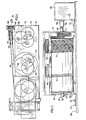
- a conventional hoist system for raising and lowering scaffolding and the like staging from the top of buildings comprises scaffolding 10 having a pair of cables 12, 14 in proximity to each end of the scaffolding for raising and lowering the scaffolding while maintaining the scaffolding in a horizontal, stable position. Cables 12, 14 pass over pulleys 16, 18 respectively which are journalled for rotation in support arms 20, 22. Support arms 20, 22 are carried by a carriage 24 having wheels 26 for traversing rails 28 permanently affixed to roof 30 parallel to the roof edge 32.
- a hoist (not shown) rotatably mounted within housing 24 receives cables 12, 14 wound thereon for raising and lowering scaffolding 10.
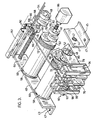
- the embodiment of the apparatus of the invention illustrated comprises frame 39 having space- apart, parallel support side walls 40, 41 affixed to a support carriage 38, Figure 5, by flanges 43, 45 and connectors 47.
- Side walls 40, 41 have openings 42 formed therein with bearings 44 for receiving the ends 46, 48 of each of shaft 50, 52 and 54.
- Shafts 50, 52 have drums 56, 58 mounted concentric thereon by drum end flanges 60, 62 secured onto the shafts.
- Shaft 54 has an external thread 64 formed along the length thereof to receive levelwinder 66, to be described.
- Each of axles 50, 52 and 54 has three cam lobes 68, 70 and 72 mounted thereon about 120° out of phase with the adjacent cam lobe and with the same degree of eccentricity relative to the axis of the respective shafts.
- Cam lobes 68, 70 and 72 have the same diameter and are secured adjacent each other.
- Cam lobes 68 preferably are permanently secured to the drum end flanges 62 or comprise an integral part thereof and cam lobes 70, 72 are mounted on the shafts by means of splines, well known in the art, such that these cam lobes can be removed for servicing and/or replacement. All cam lobes overlap the axles.
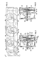
- cam lobes depicted by like numbers 68, 70 and 72 are in planar alignment with each other and are interconnected by inboard drive links 74, 76 and 78, respectively, each drive link having circular openings 80 formed therein adapted to loosely receive the cam lobes for oscillatory rotation.
- inboard used herein in connection with the links means the links oscillate about the shafts inboard of the ends of the shafts, as permitted by the overlap of the cam lobes with the axles.
- cam lobes 68, 70 and 72 will rotate therewith in an eccentric manner converting rotation of shaft 50 to oscillatory movement of drive links 74, 76 and 78 whereby following cam lobes 68, 70 and 72 and driven shafts 52, 54 will be rotated in unison with shaft 50, as shown most clearly in Figure 6.
- Shaft 50 has spline extension 82 or a keyed shaft extension adapted to be received in coupling 84 of drive motor gear reducer 86 for positive rotation of shaft 50.
- Caliper brakes depicted by numeral 90 comprise housing 92, rigidly mounted on a support frame, not shown, within which links 74, 76 and 78 oscillate.
- Housing 92 comprises a pair of end plates 94, 96 having upper and lower pairs of parallel slide rods 97, 98 secured thereto.
- Intermediate plate 99 rigidly connected to rod pairs 97, 98 has an opening 100 formed therein for slidably receiving plunger rod 101 which projects into housing 90 through opening 02 in plate 96.
- a compression spring 103 is mounted concentric with rod 101 within housing 90 and secured to rod 101 by ring 104 such that rod 101 is biased to the right as viewed in Figure 7.
- An over-centre release 105 is mounted externally of housing 90 such that longitudinal movement of rod 93 in the direction of the arrow will release plunger 101 and permit the plunger to move to the right, as shown in Figure 8.
- a pair of brake pads 124, 125 are positioned in recesses 126, 127 formed in plates 99, 94. Actuation of arm 93 during an emergency stop by an over-speed sensing device, well known in the art, allows rod 101 to be biased to the position indicated in Figure 8 whereby the oscillatory travel of links 74, 76, 78 is stopped by the frictional engagement of the brake pads on the links, or their extension.
- levelwinder 66 comprises a support block 106 threaded onto shaft 54 for axial reciprocal travel along shaft 54 as the shaft is rotated by the connecting links.
- Block 106 has a carriage 108 with two spaced-apart pairs of rollers 110 mounted thereon adapted to travel within channel track 112 to maintain block 106 in an upright position.
- Carriage 108 has bracket 114 with double- grooved pulley 116 journalled therein for leading cables 12 or 14 to drums 56, 58.
- Figure 5 illustrates another embodiment of the invention in which a pair of spaced double- grooved pulleys 116, 116' lead cables 12, 14 onto drum 52 to represent the winding of the four support cables 12, 14 on pair of drums.
- FIG. 9 shows an embodiment of the invention in which each axle 150, 151 and 152 has a single cam lobe 153 mounted thereon and secured to the end flange 155 of each drum 156.
- Link 158 interconnects the cam lobes in a driving relation as has been discussed above.
- Figure 10 shows another embodiment in which a pair of cam lobes 160, 161 at about 90° angular displacement to each other are mounted on shafts 162, 164 and 166 and interconnected by links 168, 170.
- cam lobes 172 are mounted on the axles 174, 176 and 178 of the embodiment of the invention shown in Figure 11. In all embodiments, the cam lobes overlap the axles permitting the link plates to oscillate inboard of the ends of the axles.
- Figure 12 shows an embodiment of the invention in which four drums 131,132,133 and 134 are driven in unison by the drive system of the invention depicted by numeral 135.
- Brake 136 effectively controls braking of all drums 131-134 through the connecting links.
- Levelwinder 138 with four-groove pulley 139 leads cables 140,141, 142 and 143 in vertical alignment with each other to the drums 130-134.
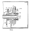
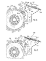
- FIG. 13-17 Another embodiment of brake mechanism shown in Figures 13-17 comprises the mechanism depicted by numeral 200 mounted axially on a shaft 202 (or drum axle) having three cam lobes 204, 206 and 208 rigidly secured together with link plates 205, 207 and 209 interconnecting said lobes to corresponding lobes of parallel axles, as shown more clearly in Figures 13 and 14.
- Hub 210 carries a backing plate 214 having a friction disc 216 and a pair of abutting control discs 218, 220 which are keyed together, such as by the use of dowels.
- Backing plate 214 is rigidly secured to hub 210 and discs 218, 220 are slidably mounted for rotation on hub 210.
- Pressure plate 224 having friction disc 226 is slidably mounted on shaft 202 in abutment against disc 220 and is biased against disc 220 by a plurality of compression springs 225 mounted coaxial with equispaced bolts 228 loosely passing through plate 224 andthreaded into hub 210. Springs 225 are compressed between ring 230 and pressure plate 224 to a predetermined setting whereby coupled discs 218, 220 normally rotate with hub 210 due to the frictional engagement of abutting friction discs 216, 226 therewith.
- Disc 220 has a plurality of equispaced cams, i.e. cam lobes 232, formed on its perimeter and disc 218 has a plurality of corresponding dogteeth 234 defining notches 236 formed on its perimeter.
- Sensor-actuator 238 pivotally-mounted on shaft 240 carried by stationary bracket 241 is biased in a clockwise direction, as viewed in Figure 13, by tension spring 242 such that cam arm 243 having cam follower 244 journalled thereon rides on cam lobes 232.
- sensor-actuator 238 pivots about shaft 240 against the bias of spring 242 to align engagement roller 246 with a notch 236 until cam follower 244 rides down the opposite side of the cam lobe 232 to pivot the sensor-actuator 238 in the opposite direction so that engagement roller 246 passes over notch 236 and tooth 234, as shown in Figure 16.
- the tension of spring 242 is adjusted by the axial movement of threaded bolt 250 connected thereto such that cam follower 244 tracks lobes 232 up to a predetermined rotary speed of shaft 202.
Landscapes
- Engineering & Computer Science (AREA)
- Architecture (AREA)
- Mechanical Engineering (AREA)
- Civil Engineering (AREA)
- Structural Engineering (AREA)
- Braking Arrangements (AREA)
- Control Of Transmission Device (AREA)
Claims (9)
Priority Applications (2)
| Application Number | Priority Date | Filing Date | Title |
|---|---|---|---|
| AT82305294T ATE24874T1 (de) | 1982-10-05 | 1982-10-05 | Antriebseinrichtung fuer seiltrommel. |
| DE8282305294T DE3275077D1 (en) | 1982-10-05 | 1982-10-05 | Drive mechanism for cable drums |
Applications Claiming Priority (1)
| Application Number | Priority Date | Filing Date | Title |
|---|---|---|---|
| CA000382425A CA1174229A (fr) | 1981-07-23 | 1981-07-23 | Mecanisme moteur pour tambour de cable |
Publications (2)
| Publication Number | Publication Date |
|---|---|
| EP0105064A1 EP0105064A1 (fr) | 1984-04-11 |
| EP0105064B1 true EP0105064B1 (fr) | 1987-01-14 |
Family
ID=4120520
Family Applications (1)
| Application Number | Title | Priority Date | Filing Date |
|---|---|---|---|
| EP82305294A Expired EP0105064B1 (fr) | 1981-07-23 | 1982-10-05 | Mécanisme de commande pour tambour à câble |
Country Status (4)
| Country | Link |
|---|---|
| US (1) | US4513952A (fr) |
| EP (1) | EP0105064B1 (fr) |
| AU (1) | AU560434B2 (fr) |
| CA (1) | CA1174229A (fr) |
Families Citing this family (17)
| Publication number | Priority date | Publication date | Assignee | Title |
|---|---|---|---|---|
| DE3520967A1 (de) * | 1985-06-12 | 1986-12-18 | Mannesmann AG, 4000 Düsseldorf | Sicherheitsbremsvorrichtung |
| US5092646A (en) * | 1989-06-20 | 1992-03-03 | Smallridge Bruce B | Double capstan winch drive |
| US5215272A (en) * | 1991-01-30 | 1993-06-01 | Sauber Charles J | Winding device having a tilting table and method |
| US5458318A (en) * | 1993-10-15 | 1995-10-17 | Kci Konecranes International Corporation | Drum brake |
| EP0796814B1 (fr) * | 1996-03-22 | 2004-09-22 | Sanyo Kogyo Co., Ltd. | Frein pour appareil de levage |
| US6644630B1 (en) * | 2002-06-19 | 2003-11-11 | Lorenz Manufacturing Company | Brake mechanism for winch assembly |
| US7210645B2 (en) * | 2004-09-13 | 2007-05-01 | Paterson Richard M | Safety element retention reel |
| DK2466252T3 (da) * | 2010-12-20 | 2013-07-29 | Christopher Bauder | Spil til tilvejebringelse af en forud bestemt længde af udrullet kabel |
| ITRM20130084A1 (it) * | 2013-02-13 | 2014-08-14 | Sfc Impresa S R L S | Carro semovente, particolarmente idoneo a supportare ponteggi sospesi. |
| KR101314637B1 (ko) | 2013-08-16 | 2013-10-04 | (주)한백 | 긴선 작업을 위한 휴대용 윈치 |
| EP3045419A1 (fr) * | 2015-01-15 | 2016-07-20 | Siemens Aktiengesellschaft | Frein de sécurité pour un dispositif de levage |
| CN105253740A (zh) * | 2015-11-26 | 2016-01-20 | 重庆钢星建筑工程有限公司 | 防倾覆防坠的制动装置 |
| CN108571160A (zh) * | 2018-07-12 | 2018-09-25 | 山东连豪机电设备有限公司 | 建筑吊篮及其提升机电机的电磁制动器和调整方法 |
| WO2020097206A1 (fr) * | 2018-11-06 | 2020-05-14 | Woods Hole Oceanographic Institution | Système éolien de niveau universel pour ensemble treuil |
| DE102019120036A1 (de) * | 2019-07-24 | 2021-01-28 | Columbus Mckinnon Industrial Products Gmbh | Hebezeug |
| CN112225109B (zh) * | 2020-09-29 | 2021-11-23 | 中建海峡建设发展有限公司 | 一种房建用物料快速提升装置 |
| DE102022119958B3 (de) * | 2022-08-09 | 2024-02-01 | Karl Storz Se & Co. Kg | Gelenkarretierung für Haltearme medizinischer Operationseinrichtungen |
Family Cites Families (12)
| Publication number | Priority date | Publication date | Assignee | Title |
|---|---|---|---|---|
| US1097078A (en) * | 1912-02-03 | 1914-05-19 | William H Box | Hoisting-machine. |
| US2546202A (en) * | 1938-04-02 | 1951-03-27 | Trouin Joseph | Apparatus for protection against falls into space |
| US2505088A (en) * | 1946-06-14 | 1950-04-25 | Internat Derrick & Equipment C | Well-drilling rig |
| DE816467C (de) * | 1950-04-15 | 1951-10-11 | Mahr Carl | Exzenter- oder Kurbeltrieb |
| US3069915A (en) * | 1958-08-04 | 1962-12-25 | Jr William S Sawle | Coupling assembly for engine crankshafts |
| US3229807A (en) * | 1963-05-31 | 1966-01-18 | Francis W Moore | Mechanical linkage |
| US3237718A (en) * | 1964-05-13 | 1966-03-01 | Ederer Corp | Two-sided suspension system for staging |
| FR1436408A (fr) * | 1964-07-04 | 1966-04-22 | Davall & Sons S | Mécanismes d'inversion du sens d'entraînement |
| FR1445823A (fr) * | 1965-07-31 | 1966-07-15 | Palmer S Travelling Gradle & S | Enrouleur de câble |
| GB1207505A (en) * | 1967-06-22 | 1970-10-07 | Herbert Clement Tampin | Hoists, particularly roof hoists |
| US4199133A (en) * | 1978-03-09 | 1980-04-22 | Pierre Gagnon | Battens system for raising and lowering sceneries on a stage |
| DD134951B1 (de) * | 1978-03-10 | 1980-01-30 | Juergen Griesshaber | Ausloeseeinrichtung,vorzugsweise fuer hubwerksbremsen |
-
1981
- 1981-07-23 CA CA000382425A patent/CA1174229A/fr not_active Expired
-
1982
- 1982-10-05 EP EP82305294A patent/EP0105064B1/fr not_active Expired
- 1982-10-05 AU AU89134/82A patent/AU560434B2/en not_active Ceased
-
1983
- 1983-06-06 US US06/501,334 patent/US4513952A/en not_active Expired - Fee Related
Also Published As
| Publication number | Publication date |
|---|---|
| AU8913482A (en) | 1984-04-12 |
| US4513952A (en) | 1985-04-30 |
| AU560434B2 (en) | 1987-04-09 |
| CA1174229A (fr) | 1984-09-11 |
| EP0105064A1 (fr) | 1984-04-11 |
Similar Documents
| Publication | Publication Date | Title |
|---|---|---|
| US4513952A (en) | Drive mechanism for cable drums | |
| FI96838B (fi) | Hissin turvajarru | |
| US5310022A (en) | Mechanical overspeed safety device | |
| US20070272490A1 (en) | Platform lifting mechanism provided with a driving pulley and corresponding driving system | |
| EP1667930A2 (fr) | Dispositif de levage, notamment ascenseur ou pont-elevateur | |
| US7484712B2 (en) | Hoist assembly | |
| US4526252A (en) | Elevator hoist unit | |
| JPS60209498A (ja) | ウオーム安全装置を有するホイスト | |
| US6318507B1 (en) | Emergency stop apparatus for elevator | |
| CN111276820A (zh) | 一种钢丝绳牵引式大型天线俯仰角调节装置及其调节方法 | |
| WO2006122796A1 (fr) | Frein annexe pour poulie motrice | |
| US5324007A (en) | Load-hoisting system having two synchronously rotating drums operating in parallel | |
| JPH0270689A (ja) | エレベータ装置 | |
| KR19990017380U (ko) | 견인 드라이브 엘리베이터 | |
| SE508605C2 (sv) | Lyftblock av hävarmstyp | |
| US4496136A (en) | Hoist | |
| CN117623056A (zh) | 安全保护系统及自驱动式轨道电梯 | |
| CA1216245A (fr) | Mecanisme de frein | |
| WO1993023324A1 (fr) | Dispositif d'actionnement lineaire a embrayage pour portes d'ascenceur | |
| CN112591641A (zh) | 一种绳索控制装置 | |
| CN214114743U (zh) | 一种绳索控制装置 | |
| ZA200106542B (en) | Lifting jack. | |
| JPS5974897A (ja) | ケ−ブル巻上げドラム駆動装置 | |
| CN200988715Y (zh) | 一种电梯的无绳限速系统 | |
| JP2657551B2 (ja) | ホイスト装置 |
Legal Events
| Date | Code | Title | Description |
|---|---|---|---|
| PUAI | Public reference made under article 153(3) epc to a published international application that has entered the european phase |
Free format text: ORIGINAL CODE: 0009012 |
|
| AK | Designated contracting states |
Designated state(s): AT BE DE FR GB IT NL |
|
| 17P | Request for examination filed |
Effective date: 19841001 |
|
| GRAA | (expected) grant |
Free format text: ORIGINAL CODE: 0009210 |
|
| AK | Designated contracting states |
Kind code of ref document: B1 Designated state(s): AT BE DE FR GB IT NL |
|
| PG25 | Lapsed in a contracting state [announced via postgrant information from national office to epo] |
Ref country code: NL Effective date: 19870114 Ref country code: IT Free format text: LAPSE BECAUSE OF FAILURE TO SUBMIT A TRANSLATION OF THE DESCRIPTION OR TO PAY THE FEE WITHIN THE PRESCRIBED TIME-LIMIT;WARNING: LAPSES OF ITALIAN PATENTS WITH EFFECTIVE DATE BEFORE 2007 MAY HAVE OCCURRED AT ANY TIME BEFORE 2007. THE CORRECT EFFECTIVE DATE MAY BE DIFFERENT FROM THE ONE RECORDED. Effective date: 19870114 Ref country code: BE Effective date: 19870114 Ref country code: AT Effective date: 19870114 |
|
| REF | Corresponds to: |
Ref document number: 24874 Country of ref document: AT Date of ref document: 19870115 Kind code of ref document: T |
|
| REF | Corresponds to: |
Ref document number: 3275077 Country of ref document: DE Date of ref document: 19870219 |
|
| ET | Fr: translation filed | ||
| NLV1 | Nl: lapsed or annulled due to failure to fulfill the requirements of art. 29p and 29m of the patents act | ||
| PLBE | No opposition filed within time limit |
Free format text: ORIGINAL CODE: 0009261 |
|
| STAA | Information on the status of an ep patent application or granted ep patent |
Free format text: STATUS: NO OPPOSITION FILED WITHIN TIME LIMIT |
|
| 26N | No opposition filed | ||
| PGFP | Annual fee paid to national office [announced via postgrant information from national office to epo] |
Ref country code: DE Payment date: 19881014 Year of fee payment: 7 |
|
| PG25 | Lapsed in a contracting state [announced via postgrant information from national office to epo] |
Ref country code: GB Effective date: 19891005 |
|
| GBPC | Gb: european patent ceased through non-payment of renewal fee | ||
| PG25 | Lapsed in a contracting state [announced via postgrant information from national office to epo] |
Ref country code: FR Effective date: 19900629 |
|
| PG25 | Lapsed in a contracting state [announced via postgrant information from national office to epo] |
Ref country code: DE Effective date: 19900703 |
|
| REG | Reference to a national code |
Ref country code: FR Ref legal event code: ST |