EP0105089B1 - Procédé pour humidifier un courant des gaz spécialement pour installations de préparation de méthanol et/ou d'ammoniac - Google Patents
Procédé pour humidifier un courant des gaz spécialement pour installations de préparation de méthanol et/ou d'ammoniac Download PDFInfo
- Publication number
- EP0105089B1 EP0105089B1 EP83106036A EP83106036A EP0105089B1 EP 0105089 B1 EP0105089 B1 EP 0105089B1 EP 83106036 A EP83106036 A EP 83106036A EP 83106036 A EP83106036 A EP 83106036A EP 0105089 B1 EP0105089 B1 EP 0105089B1
- Authority
- EP
- European Patent Office
- Prior art keywords
- water
- gas
- gas humidifier
- humidifier
- heat exchanger
- Prior art date
- Legal status (The legal status is an assumption and is not a legal conclusion. Google has not performed a legal analysis and makes no representation as to the accuracy of the status listed.)
- Expired
Links
- 238000000034 method Methods 0.000 title claims abstract description 21
- OKKJLVBELUTLKV-UHFFFAOYSA-N Methanol Chemical compound OC OKKJLVBELUTLKV-UHFFFAOYSA-N 0.000 title description 12
- QGZKDVFQNNGYKY-UHFFFAOYSA-N Ammonia Chemical compound N QGZKDVFQNNGYKY-UHFFFAOYSA-N 0.000 title 2
- 229910021529 ammonia Inorganic materials 0.000 title 1
- XLYOFNOQVPJJNP-UHFFFAOYSA-N water Substances O XLYOFNOQVPJJNP-UHFFFAOYSA-N 0.000 claims abstract description 41
- 238000010438 heat treatment Methods 0.000 claims description 10
- 238000011144 upstream manufacturing Methods 0.000 claims description 2
- 239000000203 mixture Substances 0.000 abstract 1
- 239000007789 gas Substances 0.000 description 41
- 230000015572 biosynthetic process Effects 0.000 description 4
- 238000003786 synthesis reaction Methods 0.000 description 4
- 238000010521 absorption reaction Methods 0.000 description 2
- 238000010586 diagram Methods 0.000 description 2
- VNWKTOKETHGBQD-UHFFFAOYSA-N methane Chemical compound C VNWKTOKETHGBQD-UHFFFAOYSA-N 0.000 description 2
- 230000003197 catalytic effect Effects 0.000 description 1
- 230000002349 favourable effect Effects 0.000 description 1
- 239000003345 natural gas Substances 0.000 description 1
- 238000004886 process control Methods 0.000 description 1
- 239000002918 waste heat Substances 0.000 description 1
Images

Classifications
-
- C—CHEMISTRY; METALLURGY
- C07—ORGANIC CHEMISTRY
- C07C—ACYCLIC OR CARBOCYCLIC COMPOUNDS
- C07C31/00—Saturated compounds having hydroxy or O-metal groups bound to acyclic carbon atoms
- C07C31/02—Monohydroxylic acyclic alcohols
- C07C31/04—Methanol
-
- B—PERFORMING OPERATIONS; TRANSPORTING
- B01—PHYSICAL OR CHEMICAL PROCESSES OR APPARATUS IN GENERAL
- B01F—MIXING, e.g. DISSOLVING, EMULSIFYING OR DISPERSING
- B01F23/00—Mixing according to the phases to be mixed, e.g. dispersing or emulsifying
- B01F23/10—Mixing gases with gases
- B01F23/12—Mixing gases with gases with vaporisation of a liquid
Definitions
- the invention is directed to a method for humidifying a gas stream, in which heated water for delivering water vapor in countercurrent to the gas stream is passed through a gas humidifier and then, after feeding in the corresponding make-up water from the amount of water vapor emitted, and back to the gas humidifier in the circuit.
- the object of the invention is to provide a solution with which a gas humidification can be carried out, the water absorption of which is particularly high and comes as close as possible to the later operating conditions, but at the same time lower quality energy, in particular energy at a low temperature level, can be used.
- this object is achieved according to the invention in that partial quantities of the circulating water are removed from the gas humidifier in several stages one behind the other and the individual partial quantities are heated or heated individually and / or together.
- the invention provides that the circulating water is removed from the gas humidifier in two stages, the first partial quantity removed being greater than the second partial quantity.
- first partial quantity removed being greater than the second partial quantity.
- other quantitative ratios for example partial flows of the same size, could also be provided, but the division of the partial quantities according to the invention is particularly expedient.
- the second subset is fed to a preheating stage and then together with the first subset to a final heating stage. This procedure makes it possible to design the appropriate preheating or final heating stages in favorable temperature ranges, so that even smaller temperature differences are sufficient to heat the throughput quantities.
- make-up water quantity is supplied to the last partial quantity removed from the gas humidifier before the first preheating stage.
- the synthesis gas heat from a methanol reactor for heating the circulating water can be optimally used according to the invention that the preheating stage or stages and the final heating stage are connected in series as a heat exchanger for hot synthesis gas in a common heat flow, provided in a further embodiment may be that the partial quantity from the preceding heat exchangers located downstream in relation to the heat flow is fed together with a partial quantity from the gas humidifier to the next upstream heat exchanger.
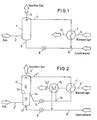
- FIG. 1 which represents the prior art that forms the starting point of the present invention
- the gas to be provided with water vapor is supplied at 2 to a gas humidifier 1 in the lower region.
- the gas enriched with water vapor leaves the gas humidifier at 3 at the top.
- Heated water is entered at 4 in the gas humidifier 1 and drawn off at 5 in the bottom of the sump, the amount of hot water sprayed in being greater than the amount withdrawn from the sump by the the gas has been enriched with water vapor.
- the heated hot water is then sprayed back into the gas humidifier 1 at 4 from the heat exchanger 7.
- the heat exchanger 7 is z. B. heated by a heat flow, such as a hot synthesis gas stream from a methanol reactor, which is indicated by the feed line 9 to the heat exchanger and the discharge line 10 with the corresponding arrows.
- the gas humidifier is basically divided into two areas; into an upper area 11 and a lower area 12.
- the upper area 11 the total amount of hot process water used is sprayed in at 4 'and acts on the total amount of the exiting gas stream which acts on the gas humidifier at 2' below and at 3 'with water vapor leaves freighted.
- the division between 11 and 12 is indicated by a dashed line 13 in the gas humidifier 1 '.
- a subset of the process water is drawn off at 14.
- the remaining amount still acts on the lower area 12 of the gas humidifier 1 'and exits at 5' in the sump.
- the first partial quantity emerging at 14 has a higher temperature than the second partial quantity or residual quantity emerging from the sump, the first partial quantity in the exemplary embodiment being intended to be larger than the remaining quantity, which is due to the different proportions of the regions 11 and 12 of the gas humidifier 1 'is indicated.
- the first subset, which leaves the gas humidifier 1 'at 14, is fed via a pump 6, a heat exchanger 7', which from the hot side of a heat flow, for. B. a synthesis gas from a methanol reactor, which in turn is indicated by an arrow line 9 '.
- the second subset leaving the sump is fed via a pump to a second heat exchanger 15, which is in the heat flow 9'-10 'on the colder side, ie. H. downstream, as shown in FIG. 2.
- This partial flow or residual flow is heated to such an extent that it has approximately the same temperature as the first partial flow leaving the gas humidifier at 14.
- the two subsets are then combined at 16 and fed to the last heat exchanger in this circuit 7 '.
- Fig. 3 shows another embodiment again with the same reference numerals for basically the same system parts. The difference is that in addition to the final heating stage through the heat exchanger 7 "in the same heat flow 9 '' 10 '', in addition to the heat exchanger 15, a further heat exchanger 17 is provided, the flow guidance of the partial quantities being basically the same here as in the example in FIG. 2, ie the coldest partial amount or residual amount from the sump 5 ", the make-up water is fed in at 8", these amounts are passed through the first preheater 15 and then fed to the further heat exchanger 17 together with a partial amount leaving the gas humidifier at 18 in order to continue there Together with the first partial amount leaving the gas humidifier 1 ′′ at 19, the total amount of water in the final heating stage, i. H. the heat exchanger 7 ".
Landscapes
- Chemical & Material Sciences (AREA)
- Organic Chemistry (AREA)
- Chemical Kinetics & Catalysis (AREA)
- Hydrogen, Water And Hydrids (AREA)
- Air Humidification (AREA)
- Organic Low-Molecular-Weight Compounds And Preparation Thereof (AREA)
- Gas Separation By Absorption (AREA)
- Treating Waste Gases (AREA)
- Investigating Or Analyzing Materials By The Use Of Fluid Adsorption Or Reactions (AREA)
- Disinfection, Sterilisation Or Deodorisation Of Air (AREA)
- Exhaust Gas Treatment By Means Of Catalyst (AREA)
- Solid-Sorbent Or Filter-Aiding Compositions (AREA)
- Emulsifying, Dispersing, Foam-Producing Or Wetting Agents (AREA)
Claims (6)
Priority Applications (1)
| Application Number | Priority Date | Filing Date | Title |
|---|---|---|---|
| AT83106036T ATE14993T1 (de) | 1982-10-01 | 1983-06-21 | Verfahren zum befeuchten eines gasstromes, insbesondere fuer methanol- und/oder ammoniakanlagen. |
Applications Claiming Priority (2)
| Application Number | Priority Date | Filing Date | Title |
|---|---|---|---|
| DE3236441 | 1982-10-01 | ||
| DE3236441A DE3236441C2 (de) | 1982-10-01 | 1982-10-01 | Verfahren zum Befeuchten eines Gasstromes, insbesondere für Methanol- und/oder Ammoniakanlagen |
Publications (2)
| Publication Number | Publication Date |
|---|---|
| EP0105089A1 EP0105089A1 (fr) | 1984-04-11 |
| EP0105089B1 true EP0105089B1 (fr) | 1985-08-21 |
Family
ID=6174718
Family Applications (1)
| Application Number | Title | Priority Date | Filing Date |
|---|---|---|---|
| EP83106036A Expired EP0105089B1 (fr) | 1982-10-01 | 1983-06-21 | Procédé pour humidifier un courant des gaz spécialement pour installations de préparation de méthanol et/ou d'ammoniac |
Country Status (10)
| Country | Link |
|---|---|
| US (1) | US4528147A (fr) |
| EP (1) | EP0105089B1 (fr) |
| JP (1) | JPS5982933A (fr) |
| AT (1) | ATE14993T1 (fr) |
| AU (1) | AU560847B2 (fr) |
| CA (1) | CA1209029A (fr) |
| DE (2) | DE3236441C2 (fr) |
| DK (1) | DK156266C (fr) |
| NO (1) | NO160332C (fr) |
| SU (1) | SU1309903A3 (fr) |
Families Citing this family (3)
| Publication number | Priority date | Publication date | Assignee | Title |
|---|---|---|---|---|
| DE102005034175A1 (de) * | 2005-07-21 | 2007-01-25 | Roche Diagnostics Gmbh | Verfahren und Vorrichtung zur Erzeugung eines Feuchtluftstromes mit definierter relativer Feuchte |
| US9327249B2 (en) | 2012-04-17 | 2016-05-03 | Air Products And Chemicals, Inc. | Systems and methods for humidifying gas streams |
| CN115121191B (zh) * | 2022-07-13 | 2023-08-04 | 重庆大学 | 一种气液两相反应制备pedot:pss的装置及方法 |
Family Cites Families (10)
| Publication number | Priority date | Publication date | Assignee | Title |
|---|---|---|---|---|
| US476274A (en) * | 1892-06-07 | Apparatus for purifying | ||
| US1986529A (en) * | 1931-05-27 | 1935-01-01 | William W Varney | Conditioning liquids and air and other gases |
| US2220219A (en) * | 1937-11-17 | 1940-11-05 | Robert B P Crawford | Regenerative cooling system |
| US2826397A (en) * | 1952-03-27 | 1958-03-11 | Svenska Flaektfabriken Ab | Scrubbers |
| DE1253679B (de) * | 1963-01-24 | 1967-11-09 | Metallgesellschaft Ag | Vorrichtung zur kontinuierlichen Durchfuehrung von chemischen Reaktionen und physikalisch-chemischen Prozessen zwischen fluessigen und gasfoermigen Stoffen |
| US3249152A (en) * | 1964-01-02 | 1966-05-03 | Monsanto Co | Heat recovery process |
| SE308657B (fr) * | 1965-06-02 | 1969-02-17 | Mo Och Domsjoe Ab | |
| DE2335659C2 (de) * | 1973-07-13 | 1982-10-28 | Krupp-Koppers Gmbh, 4300 Essen | Verfahren zur Erzeugung eines methanhaltigen Gases |
| US3927153A (en) * | 1973-08-14 | 1975-12-16 | Bethlehem Steel Corp | Process for direct cooling of corrosive industrial cases |
| US4276243A (en) * | 1978-12-08 | 1981-06-30 | Western Electric Company, Inc. | Vapor delivery control system and method |
-
1982
- 1982-10-01 DE DE3236441A patent/DE3236441C2/de not_active Expired
-
1983
- 1983-06-21 DE DE8383106036T patent/DE3360610D1/de not_active Expired
- 1983-06-21 EP EP83106036A patent/EP0105089B1/fr not_active Expired
- 1983-06-21 AT AT83106036T patent/ATE14993T1/de not_active IP Right Cessation
- 1983-06-30 NO NO832391A patent/NO160332C/no unknown
- 1983-08-26 AU AU18452/83A patent/AU560847B2/en not_active Ceased
- 1983-09-26 CA CA000437539A patent/CA1209029A/fr not_active Expired
- 1983-09-29 JP JP58179487A patent/JPS5982933A/ja active Pending
- 1983-09-29 SU SU833648850A patent/SU1309903A3/ru active
- 1983-09-30 US US06/537,636 patent/US4528147A/en not_active Expired - Fee Related
- 1983-09-30 DK DK453983A patent/DK156266C/da not_active IP Right Cessation
Also Published As
| Publication number | Publication date |
|---|---|
| SU1309903A3 (ru) | 1987-05-07 |
| DE3236441C2 (de) | 1985-09-19 |
| DK156266C (da) | 1989-12-18 |
| DK156266B (da) | 1989-07-24 |
| DK453983A (da) | 1984-04-02 |
| AU1845283A (en) | 1984-04-05 |
| EP0105089A1 (fr) | 1984-04-11 |
| NO832391L (no) | 1984-04-02 |
| ATE14993T1 (de) | 1985-09-15 |
| DE3236441A1 (de) | 1984-04-05 |
| DK453983D0 (da) | 1983-09-30 |
| JPS5982933A (ja) | 1984-05-14 |
| CA1209029A (fr) | 1986-08-05 |
| NO160332C (no) | 1989-04-12 |
| NO160332B (no) | 1989-01-02 |
| US4528147A (en) | 1985-07-09 |
| DE3360610D1 (en) | 1985-09-26 |
| AU560847B2 (en) | 1987-04-16 |
Similar Documents
| Publication | Publication Date | Title |
|---|---|---|
| EP1009920A1 (fr) | Generateur de vapeur, notamment generateur de vapeur de recuperation, et procede pour le fonctionnement de ce generateur de vapeur | |
| DE10330859A1 (de) | Verfahren zum Betrieb von emissionsfreien Gasturbinenkraftwerken | |
| DE2951557C2 (de) | Verfahren zum Betreiben eines thermischen Stofftrennprozesses mit integrierter Wärmerückführung und Vorrichtung zur Durchführung des Verfahrens | |
| DE3028913A1 (de) | Verfahren zum vorwaermen von luft | |
| DE2263319A1 (de) | Verfahren und vorrichtung zur reduktion des in luft befindlichen wasserdampfgehaltes | |
| DE3834716A1 (de) | Verfahren und vorrichtung zum aufkonzentrieren von loesungen | |
| DE2648219A1 (de) | Verfahren zum erhitzen eines stroemenden mediums in einer anlage zum eindampfen und trocknen eines produktes | |
| DD218661A5 (de) | Verfahren und vorrichtung zum wiederaufheizen entschwefelter rauchgase | |
| DE2614587A1 (de) | Verfahren zum eindampfen wasserhaltiger fluessigkeiten | |
| EP0105089B1 (fr) | Procédé pour humidifier un courant des gaz spécialement pour installations de préparation de méthanol et/ou d'ammoniac | |
| DE2632910A1 (de) | Verfahren zum eindampfen von fluessigkeiten, insbesondere von radioaktiven abwaessern | |
| DE69520366T2 (de) | Verfahren zur abschliessenden eindampfung von schwarzlauge | |
| EP0019297A2 (fr) | Méthode et dispositif pour produire de la vapeur | |
| AT395831B (de) | Verfahren und vorrichtung zur katalytischen reduktion von schadstoffen in rauchgas | |
| DE1056634B (de) | Verfahren zur Waermerueckgewinnung aus Stroemen von Gasen, Daempfen oder deren Gemischen mit einem Anfeuchtungs- und einem Trocknungsarbeitsgang | |
| AT397305B (de) | Verfahren zur trocknung eines in längsrichtung bewegten, langgestreckten gutes und anordnung zur durchführung des verfahrens | |
| DE752321C (de) | Verfahren zur Abscheidung von Wasser aus stickoxydhaltigen Gasen | |
| DE3609705C2 (fr) | ||
| DE4203684C2 (de) | Verfahren zum Aufheizen der einem Dampferzeuger eines Kraftwerks zugeführten Verbrennungsluft | |
| DE973504C (de) | Einrichtung zum Niederschlagen von ueberschuessigem Dampf bei Dampfkraftanlagen | |
| DE19524216A1 (de) | Anlage für die Vorwärmung und Entgasung von Wasser | |
| CH635165A5 (de) | Industrie-dampfturbinenanlage. | |
| DE19703468C2 (de) | Dampfkraftwerk | |
| DE2701728C3 (de) | Verfahren zum Kühlen von Gasen mit Wärmeaustauschern | |
| DE730987C (de) | Verfahren und Anlage zum Verdampfen von Fluessigkeit |
Legal Events
| Date | Code | Title | Description |
|---|---|---|---|
| PUAI | Public reference made under article 153(3) epc to a published international application that has entered the european phase |
Free format text: ORIGINAL CODE: 0009012 |
|
| 17P | Request for examination filed |
Effective date: 19840113 |
|
| AK | Designated contracting states |
Designated state(s): AT DE FR GB IT NL SE |
|
| ITF | It: translation for a ep patent filed | ||
| GRAA | (expected) grant |
Free format text: ORIGINAL CODE: 0009210 |
|
| AK | Designated contracting states |
Designated state(s): AT DE FR GB IT NL SE |
|
| REF | Corresponds to: |
Ref document number: 14993 Country of ref document: AT Date of ref document: 19850915 Kind code of ref document: T |
|
| REF | Corresponds to: |
Ref document number: 3360610 Country of ref document: DE Date of ref document: 19850926 |
|
| ET | Fr: translation filed | ||
| PLBE | No opposition filed within time limit |
Free format text: ORIGINAL CODE: 0009261 |
|
| STAA | Information on the status of an ep patent application or granted ep patent |
Free format text: STATUS: NO OPPOSITION FILED WITHIN TIME LIMIT |
|
| 26N | No opposition filed | ||
| PGFP | Annual fee paid to national office [announced via postgrant information from national office to epo] |
Ref country code: SE Payment date: 19900528 Year of fee payment: 8 |
|
| PG25 | Lapsed in a contracting state [announced via postgrant information from national office to epo] |
Ref country code: SE Effective date: 19910622 |
|
| ITTA | It: last paid annual fee | ||
| PGFP | Annual fee paid to national office [announced via postgrant information from national office to epo] |
Ref country code: DE Payment date: 19920502 Year of fee payment: 10 |
|
| PGFP | Annual fee paid to national office [announced via postgrant information from national office to epo] |
Ref country code: GB Payment date: 19920508 Year of fee payment: 10 |
|
| PGFP | Annual fee paid to national office [announced via postgrant information from national office to epo] |
Ref country code: FR Payment date: 19920521 Year of fee payment: 10 |
|
| PGFP | Annual fee paid to national office [announced via postgrant information from national office to epo] |
Ref country code: AT Payment date: 19920625 Year of fee payment: 10 |
|
| PGFP | Annual fee paid to national office [announced via postgrant information from national office to epo] |
Ref country code: NL Payment date: 19920630 Year of fee payment: 10 |
|
| PG25 | Lapsed in a contracting state [announced via postgrant information from national office to epo] |
Ref country code: GB Effective date: 19930621 Ref country code: AT Effective date: 19930621 |
|
| PG25 | Lapsed in a contracting state [announced via postgrant information from national office to epo] |
Ref country code: NL Effective date: 19940101 |
|
| GBPC | Gb: european patent ceased through non-payment of renewal fee |
Effective date: 19930621 |
|
| NLV4 | Nl: lapsed or anulled due to non-payment of the annual fee | ||
| PG25 | Lapsed in a contracting state [announced via postgrant information from national office to epo] |
Ref country code: FR Effective date: 19940228 |
|
| PG25 | Lapsed in a contracting state [announced via postgrant information from national office to epo] |
Ref country code: DE Effective date: 19940301 |
|
| REG | Reference to a national code |
Ref country code: FR Ref legal event code: ST |
|
| EUG | Se: european patent has lapsed |
Ref document number: 83106036.3 Effective date: 19920109 |