EP0105108A1 - Hubkolbenbrennkraftmaschine - Google Patents
Hubkolbenbrennkraftmaschine Download PDFInfo
- Publication number
- EP0105108A1 EP0105108A1 EP83107095A EP83107095A EP0105108A1 EP 0105108 A1 EP0105108 A1 EP 0105108A1 EP 83107095 A EP83107095 A EP 83107095A EP 83107095 A EP83107095 A EP 83107095A EP 0105108 A1 EP0105108 A1 EP 0105108A1
- Authority
- EP
- European Patent Office
- Prior art keywords
- heat
- sealing element
- insulating layer
- cylinder
- cylinder head
- Prior art date
- Legal status (The legal status is an assumption and is not a legal conclusion. Google has not performed a legal analysis and makes no representation as to the accuracy of the status listed.)
- Granted
Links
- 238000002485 combustion reaction Methods 0.000 title claims abstract description 19
- 238000007789 sealing Methods 0.000 claims abstract description 34
- 229910052751 metal Inorganic materials 0.000 claims abstract description 13
- 239000002184 metal Substances 0.000 claims abstract description 13
- 229910010293 ceramic material Inorganic materials 0.000 claims description 4
- 229910000505 Al2TiO5 Inorganic materials 0.000 claims description 2
- 229910001234 light alloy Inorganic materials 0.000 claims description 2
- AABBHSMFGKYLKE-SNAWJCMRSA-N propan-2-yl (e)-but-2-enoate Chemical compound C\C=C\C(=O)OC(C)C AABBHSMFGKYLKE-SNAWJCMRSA-N 0.000 claims description 2
- 238000009413 insulation Methods 0.000 abstract 1
- 230000008646 thermal stress Effects 0.000 abstract 1
- 239000000919 ceramic Substances 0.000 description 3
- 229910001018 Cast iron Inorganic materials 0.000 description 2
- 230000006378 damage Effects 0.000 description 2
- 230000000694 effects Effects 0.000 description 2
- 230000017525 heat dissipation Effects 0.000 description 2
- 239000002131 composite material Substances 0.000 description 1
- 238000001816 cooling Methods 0.000 description 1
- 229910001385 heavy metal Inorganic materials 0.000 description 1
- 239000012212 insulator Substances 0.000 description 1
Images
Classifications
-
- F—MECHANICAL ENGINEERING; LIGHTING; HEATING; WEAPONS; BLASTING
- F16—ENGINEERING ELEMENTS AND UNITS; GENERAL MEASURES FOR PRODUCING AND MAINTAINING EFFECTIVE FUNCTIONING OF MACHINES OR INSTALLATIONS; THERMAL INSULATION IN GENERAL
- F16J—PISTONS; CYLINDERS; SEALINGS
- F16J15/00—Sealings
- F16J15/02—Sealings between relatively-stationary surfaces
- F16J15/06—Sealings between relatively-stationary surfaces with solid packing compressed between sealing surfaces
- F16J15/08—Sealings between relatively-stationary surfaces with solid packing compressed between sealing surfaces with exclusively metal packing
- F16J15/0806—Sealings between relatively-stationary surfaces with solid packing compressed between sealing surfaces with exclusively metal packing characterised by material or surface treatment
-
- F—MECHANICAL ENGINEERING; LIGHTING; HEATING; WEAPONS; BLASTING
- F02—COMBUSTION ENGINES; HOT-GAS OR COMBUSTION-PRODUCT ENGINE PLANTS
- F02F—CYLINDERS, PISTONS OR CASINGS, FOR COMBUSTION ENGINES; ARRANGEMENTS OF SEALINGS IN COMBUSTION ENGINES
- F02F1/00—Cylinders; Cylinder heads
- F02F1/02—Cylinders; Cylinder heads having cooling means
- F02F1/04—Cylinders; Cylinder heads having cooling means for air cooling
-
- F—MECHANICAL ENGINEERING; LIGHTING; HEATING; WEAPONS; BLASTING
- F02—COMBUSTION ENGINES; HOT-GAS OR COMBUSTION-PRODUCT ENGINE PLANTS
- F02F—CYLINDERS, PISTONS OR CASINGS, FOR COMBUSTION ENGINES; ARRANGEMENTS OF SEALINGS IN COMBUSTION ENGINES
- F02F11/00—Arrangements of sealings in combustion engines
- F02F11/002—Arrangements of sealings in combustion engines involving cylinder heads
-
- F—MECHANICAL ENGINEERING; LIGHTING; HEATING; WEAPONS; BLASTING
- F16—ENGINEERING ELEMENTS AND UNITS; GENERAL MEASURES FOR PRODUCING AND MAINTAINING EFFECTIVE FUNCTIONING OF MACHINES OR INSTALLATIONS; THERMAL INSULATION IN GENERAL
- F16J—PISTONS; CYLINDERS; SEALINGS
- F16J15/00—Sealings
- F16J15/02—Sealings between relatively-stationary surfaces
- F16J15/06—Sealings between relatively-stationary surfaces with solid packing compressed between sealing surfaces
- F16J15/08—Sealings between relatively-stationary surfaces with solid packing compressed between sealing surfaces with exclusively metal packing
- F16J15/0881—Sealings between relatively-stationary surfaces with solid packing compressed between sealing surfaces with exclusively metal packing the sealing effect being obtained by plastic deformation of the packing
Definitions
- the invention relates to a reciprocating internal combustion engine having an in particular as a metal ring formed cylinder head sealing element, which is in a recess provided in a light alloy cylinder head recess - is arranged and a sealing surface to a. Cylinder tube forms.
- Sealing surfaces of light metal cylinder heads which are braced with a cast iron cylinder tube, are exposed to the highest loads due to high surface pressure and radial relative movements of the cylinder head and cylinder tube due to the different thermal expansion behavior of light metal and cast iron, which can lead to destruction of the sealing surfaces and failure of the cylinder unit.
- the invention has for its object to improve a cylinder of the type mentioned in a simple manner in that temperature stresses in the light metal cylinder head are reduced. Furthermore, the sealing surfaces should have the highest possible stability.
- the sealing element is provided with a heat-insulating layer at least on the surface on the combustion chamber side.
- a ceramic material in particular aluminum titanate (A12TiOS), is particularly well suited as a heat-insulating layer, the simplest version being a ring-shaped sealing element according to the invention can be produced by A b puncturing a composite pipe with a shrunk ceramic sleeve.
- A12TiOS aluminum titanate
- the cylinder tube is provided on the end face with a heat-insulating component, in particular made of a ceramic material, which forms a contact surface for the heat-insulating layer of the sealing element.
- a heat-insulating component in particular made of a ceramic material, which forms a contact surface for the heat-insulating layer of the sealing element.
- the bearing surface of the heat-insulating layer of the sealing element on the cylinder tube side and the bearing surface of the heat-insulating component provided in the cylinder tube have the same cross-section and that the heat-insulating layer of the sealing element be provided with a chamfer on the inner surface of the combustion chamber. This ensures that the thermal insulator layer. Sealing element rests on a surface with approximately the same strength, and further the sealing element is determined by the particular symmetrical A nfasung an insensitive bearing part.
- the recess for receiving the sealing element is wider than the sealing element.
- the light metal cylinder head is provided with an inlet and outlet channel 2a, 2b and with 3 the cylinder tube.
- the light metal cylinder head 1 has a recess 5.
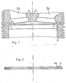
- the sealing element 4 is provided with a ceramic heat-insulating layer 4a, which is chamfered symmetrically and rests on a ceramic heat-insulating component 7, which is arranged in the front inner surface of the cylinder tube 3.
- F ig. 2 illustrates in a cut E inzeldar- position, the heat-insulating seal member 4, 4a of the cylinder according to the invention.
Landscapes
- Engineering & Computer Science (AREA)
- General Engineering & Computer Science (AREA)
- Mechanical Engineering (AREA)
- Chemical & Material Sciences (AREA)
- Combustion & Propulsion (AREA)
- Cylinder Crankcases Of Internal Combustion Engines (AREA)
- Pistons, Piston Rings, And Cylinders (AREA)
- Combustion Methods Of Internal-Combustion Engines (AREA)
- Gasket Seals (AREA)
Abstract
Description
- Die Erfindung bezieht sich auf eine Hubkolbenbrennkraftmaschine mit einem insbesondere als Metallring ausgebildeten zylinderkopfdichtelement, das in einer in einem Leichtmetallzylinderkopf vorgesehenen Ausnehmung ange- ordnet ist und eine Dichtfläche zu einen. Zylinderrohr bildet.
- Dichtflächen von Leichtmetallzylinderköpfen, die mit einem gußeisernen Zylinderrohr verspannt sind, sind aufgrund hoher Flächenpressung und radialer Relativbewegungen von Zylinderkopf und Zylinderrohr infolge eines unterschiedlichen Wärmeausdehnungsverhaltens von Leichtmetall und Gußeisen höchsten Belastungen ausgesetzt, die zur Zerstörung der Dichtflächen und zum Ausfall'der Zylindereinheit führen können.
- Es ist ein Zylinder für Hubkolbenbrennkraftmaschinen bekannt (DE-PS 10 28 386), bei dem die Dichtfläche des Leichtmetallzylinderkopfes durch einen eingegossenen Schwermetallring gebildet wird. Hierdurch werden zwar die radialen Relativbewegungen an der Dichtfläche von Zylinderkopf und Zylinderrohr durch annähernd gleiches Wärmeausdehnungsverhalten des Dichtringes und des Zylinderrohres weitgehend vermieden, jedoch treten erhebliche Temperaturspannnungen im Leichtmetallzylinderkopf auf, die Wärmerisse und eine Zerstörung des zylinderkopfes verursachen können.
- Der Erfindung liegt die Aufgabe zugrunde, einen Zylinder der eingangs genannten Art in einfacher Weise dahingehend zu verbessern, daß Temperaturspannungen im Leichtmetallzylinderkopf vermindert werden. Weiterhin sollen die Dichtflächen eine möglichst hohe Standfestigkeit aufweisen.
- Diese Aufgabe wird erfindungsgemäß dadurch gelöst, daß das Dichtelement zumindest an der brennraumseitigen Fläche mit einer wärmeisolierenden Schicht versehen ist. Durch die behinderte Wärmeabfuhr wird einerseits ein Abbau von Temperaturspitzen und andererseits eine Vergleichmäßigung der Temperaturen bei Lastwechselbetrieb sowohl im Dichtelement als auch im Leichtmetallzylinderkopf erreicht, so daß die durch unterschiedliche Wärmeausdehnung hervorgerufenen Temperaturspannungen des bekannten Zylinders und radiale Relativbewegungen praktisch auszuschließen sind. Ein weiterer wesentlicher Vorteil der Erfindung ist darin zu sehen, daß durch die behinderte Wärmeabfuhr die Brennraumtemperatur gesteigert werden kann, wodurch die insbesondere im Kaltstart- und Teillastbetrieb erhöhte HC-Emission gesenkt wird und weiterhin der Gesamtwirkungsgrad einer mit dem erfindungsgemäßen Zylinder ausgestatteten Brennkraftmachine in vorteilhafter Weise verbessert wird.
- Als wärmeisolierende Schicht ist ein keramischer Werkstoff, insbesondere Aluminiumtitanat (A12TiOS) besonders gut geeignet, wobei in einfachster Ausführung ein erfindungsgemäßes ringförmiges Dichtelement durch Ab-stechen von einem Verbundrohr mit eingeschrumpfter Keramikhülse hergestellt sein kann.
- Eine besonders vorteilhafte Wirkung wird mit dem erfindungsgemäß vorgeschlagenen Zylinder erzielt, wenn entsprechend Anspruch 3 das zylinderrohr an der stirnseitigen Fläche mit einem insbesondere aus einem keramischen Werkstoff bestehenden wärmeisolierenden Bauteil versehen ist, das eine Auflagefläche für die wärmeisolierende Schicht des Dichtelementes bildet. Hierdurch wird der gesamte Dichtflächenbereich von Leichtmetallzylinderkopf, Dichtelement und zylinderrohr zum Brennraum hin wärmeisoliert, so daß z. B. Brennraumtemperaturerhöhungen bei Lastwechseln praktisch keine Auswirkungen mehr auf den Dichtflächenbereich haben, der folglich sogar eine erhöhte Kühlung erfährt, so daß eine hohe Standzeit der Dichtflächen sichergestellt ist.
- In weiteren Ausgestaltungen der Erfindung wird vorgeschlagen, daß die zylinderrohrseitige Auflagefläche der wärmeisolierenden Schicht des Dichtelementes und die zylinderkopfseitige Auflagefläche des im Zylinderrohr vorgesehenen wärmeisolierenden Bauteils den gleichen Querschnitt aufweisen und daß die wärmeisolierende Schicht des Dichtelementes an der brennraumseitigen Innenfläche mit einer Anfasung versehen ist. Hierdurch wird sichergestellt, daß die wärmeisolierende Schicht des. Dichtelementes an einer Fläche mit annähernd gleicher Festigkeit aufliegt und ferner wird das Dichtelement durch die insbesondere symmetrische Anfasung ein unempfindliches Lagerteil.
- Um das Dichtelement mit radialem Spiel im Hinblick auf die bruchempfindliche wärmeisolierende Schicht im Leichtmetallzylinderkopf vorsehen zu können, wird entsprechend Anspruch 6 vorgeschlagen, daß die Ausnehmung zur Aufnahme des Dichtelementes breiter als das Dichtelement ausgebildet ist.
- Die zeichnerische Darstellung zeigt die Erfindung anhand eines ausgewählten Ausführungsbeispieles. Es stellen dar:
- Fig. 1 einen geschnittenen Ausschnitt durch die Verbindungsstelle Zylinderkopf - Zylinderrohr bei einer luftgekühlten Brennkraftmaschine,
- Fig. 2 einen Querschnitt des Dichtelementes.
- In Fig. 1 ist ausschnittsweise der Zylinder einer luftgekühlten Brennkraftmaschine an der Verbindungsstelle Zylinderkopf - Zylinderrohr dargestellt. Mit 1 ist der mit einem Einlaß- und Auslaßkanal 2a, 2b versehene Leichtmetallzylinderkopf und mit 3 das Zylinderrohr bezeichnet. Zur Aufnahme des ringförmigen Dichtelementes 4 weist der Leichtmetallzylinderkopf 1 eine Ausnehmung 5 auf. Zum Brennraum 6 hin ist das Dichtelement 4 mit einer keramischen wärmeisolierenden Schicht 4a versehen, die symmetrisch angefast ist und an einem keramischen wärmeisolierenden Bauteil 7 aufliegt, das in der stirnseitigen Innenfläche des Zylinderrohres 3 angeordnet ist.
- Fig. 2 verdeutlicht in einer geschnittenen Einzeldar- stellung das wärmeisolierende Dichtelement 4, 4a des erfindungsgemäßen Zylinders.
Claims (6)
dadurch gekennzeichnet, daß das Dichtelement (4) zumindest an der brennraumseitigen Fläche mit einer wärmeisolierenden Schicht (4a) versehen ist.
dadurch gekennzeichnet, daß die wärmeisolierende Schicht (4a) an der brennraumseitigen Innenfläche mit einer Anfasung versehen ist.
dadurch gekennzeichnet, daß die Ausnehmung (5) zur Aufnahme des Dichtelementes (4, 4a) breiter als das Dichtelement (4, 4a) ausgebildet ist.
Priority Applications (1)
| Application Number | Priority Date | Filing Date | Title |
|---|---|---|---|
| AT83107095T ATE24749T1 (de) | 1982-09-30 | 1983-07-20 | Hubkolbenbrennkraftmaschine. |
Applications Claiming Priority (2)
| Application Number | Priority Date | Filing Date | Title |
|---|---|---|---|
| DE19823236185 DE3236185A1 (de) | 1982-09-30 | 1982-09-30 | Hubkolbenbrennkraftmaschine |
| DE3236185 | 1982-09-30 |
Publications (2)
| Publication Number | Publication Date |
|---|---|
| EP0105108A1 true EP0105108A1 (de) | 1984-04-11 |
| EP0105108B1 EP0105108B1 (de) | 1987-01-07 |
Family
ID=6174546
Family Applications (1)
| Application Number | Title | Priority Date | Filing Date |
|---|---|---|---|
| EP83107095A Expired EP0105108B1 (de) | 1982-09-30 | 1983-07-20 | Hubkolbenbrennkraftmaschine |
Country Status (5)
| Country | Link |
|---|---|
| US (1) | US4513703A (de) |
| EP (1) | EP0105108B1 (de) |
| AT (1) | ATE24749T1 (de) |
| CA (1) | CA1214368A (de) |
| DE (2) | DE3236185A1 (de) |
Families Citing this family (11)
| Publication number | Priority date | Publication date | Assignee | Title |
|---|---|---|---|---|
| US4917062A (en) * | 1989-04-17 | 1990-04-17 | Tapper Thomas E | Cylinder head gasket elimination process |
| US5072697A (en) * | 1991-03-13 | 1991-12-17 | Sputhe Alan C | Sealing apparatus for an internal combustion engine |
| ZA948161B (en) * | 1993-10-18 | 1995-05-25 | Dale Graham Hobson | Sealing of cylinder heads |
| DE4342183A1 (de) * | 1993-12-10 | 1995-06-14 | Kloeckner Humboldt Deutz Ag | Brennkraftmaschine mit einer Zylinderrohreinlage |
| GB0220685D0 (en) * | 2002-09-05 | 2002-10-16 | Innogy Plc | A cylinder for an internal combustion engine |
| DE102007007977A1 (de) * | 2007-02-17 | 2008-08-21 | Deutz Power Systems Gmbh | Luftspaltisolation an einer Zylinderbüchse |
| US11466651B2 (en) * | 2018-08-01 | 2022-10-11 | Ford Global Technologies, Llc | Fuel injector with duct assembly |
| WO2021242565A1 (en) * | 2020-05-27 | 2021-12-02 | Cummins Inc. | Anti-polish ring for an engine cylinder |
| JP7342998B1 (ja) | 2022-03-24 | 2023-09-12 | いすゞ自動車株式会社 | 内燃機関 |
| JP7338734B1 (ja) | 2022-04-13 | 2023-09-05 | いすゞ自動車株式会社 | 内燃機関 |
| JP7302701B1 (ja) | 2022-04-13 | 2023-07-04 | いすゞ自動車株式会社 | 内燃機関 |
Citations (5)
| Publication number | Priority date | Publication date | Assignee | Title |
|---|---|---|---|---|
| FR1066721A (fr) * | 1951-12-03 | 1954-06-09 | Daimler Benz Ag | Garniture d'étanchéité pour culasse de cylindre de moteurs à combustion interne |
| DE967418C (de) * | 1943-09-04 | 1957-11-07 | Kloeckner Humboldt Deutz Ag | Zylinderdeckel fuer luftgekuehlte Brennkraftmaschinen |
| DE1028386B (de) * | 1957-02-28 | 1958-04-17 | Motoren Werke Mannheim Ag | Leichtmetallzylinderkopf fuer Brennkraftmaschinen |
| FR2410141A1 (fr) * | 1977-11-25 | 1979-06-22 | Kloeckner Humboldt Deutz Ag | Cylindre de moteur a combustion interne a pistons alternatifs |
| EP0046505A1 (de) * | 1980-08-23 | 1982-03-03 | Klöckner-Humboldt-Deutz Aktiengesellschaft | Zylinder für Hubkolbenmaschinen |
Family Cites Families (8)
| Publication number | Priority date | Publication date | Assignee | Title |
|---|---|---|---|---|
| US1825769A (en) * | 1929-09-16 | 1931-10-06 | Barbarou Marius Jean-Baptiste | Construction of the cylinders of internal combustion engines |
| DE1017416B (de) * | 1952-02-23 | 1957-10-10 | Paul Lechler Fa | Zylinderkopf-Flachdichtung |
| DE1044515B (de) * | 1957-10-15 | 1958-11-20 | Daimler Benz Ag | Zylinderkopfdichtung |
| DE1897682U (de) * | 1960-07-29 | 1964-07-30 | Maschf Augsburg Nuernberg Ag | Zylinderkopfdichtung fuer kolbenmaschinen. |
| DE1630721A1 (de) * | 1967-08-01 | 1971-06-09 | Linde Ag | Fahrzeug mit lenkbaren Raedern |
| DE2937788A1 (de) * | 1979-09-19 | 1981-04-02 | Klöckner-Humboldt-Deutz AG, 5000 Köln | Leichtmetallzylinderkopf fuer brennkraftmaschinen |
| SE433376B (sv) * | 1979-10-22 | 1984-05-21 | Saab Scania Ab | Kolvmotor med vermeisolerat forbrenningsrum |
| US4328772A (en) * | 1980-01-14 | 1982-05-11 | Cummins Engine Company, Inc. | Combustion chamber for an internal combustion engine |
-
1982
- 1982-09-30 DE DE19823236185 patent/DE3236185A1/de not_active Withdrawn
-
1983
- 1983-07-20 DE DE8383107095T patent/DE3368964D1/de not_active Expired
- 1983-07-20 EP EP83107095A patent/EP0105108B1/de not_active Expired
- 1983-07-20 AT AT83107095T patent/ATE24749T1/de not_active IP Right Cessation
- 1983-09-28 CA CA000437732A patent/CA1214368A/en not_active Expired
- 1983-09-28 US US06/536,897 patent/US4513703A/en not_active Expired - Fee Related
Patent Citations (5)
| Publication number | Priority date | Publication date | Assignee | Title |
|---|---|---|---|---|
| DE967418C (de) * | 1943-09-04 | 1957-11-07 | Kloeckner Humboldt Deutz Ag | Zylinderdeckel fuer luftgekuehlte Brennkraftmaschinen |
| FR1066721A (fr) * | 1951-12-03 | 1954-06-09 | Daimler Benz Ag | Garniture d'étanchéité pour culasse de cylindre de moteurs à combustion interne |
| DE1028386B (de) * | 1957-02-28 | 1958-04-17 | Motoren Werke Mannheim Ag | Leichtmetallzylinderkopf fuer Brennkraftmaschinen |
| FR2410141A1 (fr) * | 1977-11-25 | 1979-06-22 | Kloeckner Humboldt Deutz Ag | Cylindre de moteur a combustion interne a pistons alternatifs |
| EP0046505A1 (de) * | 1980-08-23 | 1982-03-03 | Klöckner-Humboldt-Deutz Aktiengesellschaft | Zylinder für Hubkolbenmaschinen |
Also Published As
| Publication number | Publication date |
|---|---|
| EP0105108B1 (de) | 1987-01-07 |
| CA1214368A (en) | 1986-11-25 |
| DE3236185A1 (de) | 1984-04-05 |
| DE3368964D1 (en) | 1987-02-12 |
| US4513703A (en) | 1985-04-30 |
| ATE24749T1 (de) | 1987-01-15 |
Similar Documents
| Publication | Publication Date | Title |
|---|---|---|
| DE2851507C2 (de) | Isolations-Federkörper und dessen Verwendung | |
| DE68912496T2 (de) | Zylinderbuchse für eine Brennkraftmaschine. | |
| EP0878647B1 (de) | Kolbenring aus Gusseisen | |
| DE3506069A1 (de) | Maschinenteil fuer eine brennkraftmaschine und verfahren zu dessen herstellung | |
| DE3118498A1 (de) | Oelgekuehlte zylinderbuechsen-vorrichtung | |
| DE3307114C2 (de) | Zylinderkopf eines Kolbenmotors | |
| DE3236185A1 (de) | Hubkolbenbrennkraftmaschine | |
| DE3100755A1 (de) | Zylinderkopf fuer eine brennkraftmaschine | |
| CH653099A5 (de) | Kolben fuer eine brennkraftmaschine. | |
| DE3215709C2 (de) | ||
| DE3442488A1 (de) | Fluessigkeitsgekuehlte hubkolbenbrennkraftmaschine mit in reihe angeordneten zylindern | |
| DE3536866A1 (de) | Vorkammerkonstruktion einer brennkraftmaschine | |
| EP0097320A2 (de) | Vor- oder Wirbelkammer für Verbennungsmotoren | |
| DE4425467A1 (de) | Zylinderkopfverschraubung einer Brennkraftmaschine | |
| DE19837596C1 (de) | Kolben für Verbrennungskraftmaschinen | |
| DE3031926A1 (de) | Zylinder fuer hubkolbenmaschinen | |
| DE102007007977A1 (de) | Luftspaltisolation an einer Zylinderbüchse | |
| DE3134771C2 (de) | Zylinderbuchse für Brennkraftkolbenmaschinen | |
| DE2421240A1 (de) | Gehaeusemantel fuer eine rotationskolbenbrennkraftmaschine | |
| AT380311B (de) | Kolben fuer dieselmotoren mit direkter kraftstoffeinspritzung | |
| DE69510007T2 (de) | Gleitteil und Herstellungsverfahren | |
| EP0777072A1 (de) | Kolben-Pleuelverbindung | |
| DE29600036U1 (de) | Kolben von Dieselmotoren | |
| EP0172492A2 (de) | Ventil für eine Brennkraftmaschine | |
| AT220889B (de) | Zylinderkopf für wassergekühlte, ventilgesteuerte Brennkraftmaschinen |
Legal Events
| Date | Code | Title | Description |
|---|---|---|---|
| PUAI | Public reference made under article 153(3) epc to a published international application that has entered the european phase |
Free format text: ORIGINAL CODE: 0009012 |
|
| 17P | Request for examination filed |
Effective date: 19840203 |
|
| AK | Designated contracting states |
Designated state(s): AT DE FR GB IT |
|
| GRAA | (expected) grant |
Free format text: ORIGINAL CODE: 0009210 |
|
| AK | Designated contracting states |
Kind code of ref document: B1 Designated state(s): AT DE FR GB IT |
|
| REF | Corresponds to: |
Ref document number: 24749 Country of ref document: AT Date of ref document: 19870115 Kind code of ref document: T |
|
| ITF | It: translation for a ep patent filed | ||
| REF | Corresponds to: |
Ref document number: 3368964 Country of ref document: DE Date of ref document: 19870212 |
|
| ET | Fr: translation filed | ||
| PLBE | No opposition filed within time limit |
Free format text: ORIGINAL CODE: 0009261 |
|
| STAA | Information on the status of an ep patent application or granted ep patent |
Free format text: STATUS: NO OPPOSITION FILED WITHIN TIME LIMIT |
|
| 26N | No opposition filed | ||
| PGFP | Annual fee paid to national office [announced via postgrant information from national office to epo] |
Ref country code: FR Payment date: 19890607 Year of fee payment: 7 Ref country code: AT Payment date: 19890607 Year of fee payment: 7 |
|
| PGFP | Annual fee paid to national office [announced via postgrant information from national office to epo] |
Ref country code: GB Payment date: 19890630 Year of fee payment: 7 |
|
| ITTA | It: last paid annual fee | ||
| PG25 | Lapsed in a contracting state [announced via postgrant information from national office to epo] |
Ref country code: DE Effective date: 19900403 |
|
| PG25 | Lapsed in a contracting state [announced via postgrant information from national office to epo] |
Ref country code: GB Effective date: 19900720 Ref country code: AT Effective date: 19900720 |
|
| GBPC | Gb: european patent ceased through non-payment of renewal fee | ||
| PG25 | Lapsed in a contracting state [announced via postgrant information from national office to epo] |
Ref country code: FR Effective date: 19910329 |
|
| REG | Reference to a national code |
Ref country code: FR Ref legal event code: ST |