EP0105302B1 - Supports ameliores de corps de chauffe destines aux fours de recuit - Google Patents
Supports ameliores de corps de chauffe destines aux fours de recuit Download PDFInfo
- Publication number
- EP0105302B1 EP0105302B1 EP83901180A EP83901180A EP0105302B1 EP 0105302 B1 EP0105302 B1 EP 0105302B1 EP 83901180 A EP83901180 A EP 83901180A EP 83901180 A EP83901180 A EP 83901180A EP 0105302 B1 EP0105302 B1 EP 0105302B1
- Authority
- EP
- European Patent Office
- Prior art keywords
- support
- heating body
- anyone
- foregoing
- support according
- Prior art date
- Legal status (The legal status is an assumption and is not a legal conclusion. Google has not performed a legal analysis and makes no representation as to the accuracy of the status listed.)
- Expired
Links
- 238000010438 heat treatment Methods 0.000 title claims abstract description 33
- 238000000137 annealing Methods 0.000 title claims description 6
- 229910001220 stainless steel Inorganic materials 0.000 claims description 6
- 239000010935 stainless steel Substances 0.000 claims description 6
- 239000007789 gas Substances 0.000 claims description 4
- 239000012212 insulator Substances 0.000 claims description 3
- 238000006073 displacement reaction Methods 0.000 claims 1
- 229910000831 Steel Inorganic materials 0.000 description 5
- 239000010959 steel Substances 0.000 description 5
- 125000006850 spacer group Chemical group 0.000 description 3
- 238000009434 installation Methods 0.000 description 2
- 238000012423 maintenance Methods 0.000 description 2
- 210000000056 organ Anatomy 0.000 description 2
- 208000031968 Cadaver Diseases 0.000 description 1
- 230000002411 adverse Effects 0.000 description 1
- 238000004873 anchoring Methods 0.000 description 1
- 238000011109 contamination Methods 0.000 description 1
- 238000005238 degreasing Methods 0.000 description 1
- 238000010304 firing Methods 0.000 description 1
- 238000000034 method Methods 0.000 description 1
- 239000011490 mineral wool Substances 0.000 description 1
- 230000007935 neutral effect Effects 0.000 description 1
- 230000003071 parasitic effect Effects 0.000 description 1
- 239000008188 pellet Substances 0.000 description 1
- 230000003134 recirculating effect Effects 0.000 description 1
- 239000000725 suspension Substances 0.000 description 1
- 230000008961 swelling Effects 0.000 description 1
Images
Classifications
-
- C—CHEMISTRY; METALLURGY
- C21—METALLURGY OF IRON
- C21D—MODIFYING THE PHYSICAL STRUCTURE OF FERROUS METALS; GENERAL DEVICES FOR HEAT TREATMENT OF FERROUS OR NON-FERROUS METALS OR ALLOYS; MAKING METAL MALLEABLE, e.g. BY DECARBURISATION OR TEMPERING
- C21D9/00—Heat treatment, e.g. annealing, hardening, quenching or tempering, adapted for particular articles; Furnaces therefor
- C21D9/0006—Details, accessories not peculiar to any of the following furnaces
-
- F—MECHANICAL ENGINEERING; LIGHTING; HEATING; WEAPONS; BLASTING
- F23—COMBUSTION APPARATUS; COMBUSTION PROCESSES
- F23C—METHODS OR APPARATUS FOR COMBUSTION USING FLUID FUEL OR SOLID FUEL SUSPENDED IN A CARRIER GAS OR AIR
- F23C3/00—Combustion apparatus characterised by the shape of the combustion chamber
- F23C3/002—Combustion apparatus characterised by the shape of the combustion chamber the chamber having an elongated tubular form, e.g. for a radiant tube
-
- F—MECHANICAL ENGINEERING; LIGHTING; HEATING; WEAPONS; BLASTING
- F27—FURNACES; KILNS; OVENS; RETORTS
- F27D—DETAILS OR ACCESSORIES OF FURNACES, KILNS, OVENS OR RETORTS, IN SO FAR AS THEY ARE OF KINDS OCCURRING IN MORE THAN ONE KIND OF FURNACE
- F27D1/00—Casings; Linings; Walls; Roofs
- F27D1/0003—Linings or walls
- F27D1/0036—Linings or walls comprising means for supporting electric resistances in the furnace
Definitions
- the present invention relates to improved supports intended in particular for heating bodies of annealing ovens.
- the heaters are used in particular in ovens ensuring the continuous annealing of steel strips.
- a coil of steel strip is unwound and the steel strip passes through a degreasing device. It is dried by hot air, before entering the oven which is divided into a heating section and a holding section. There is a neutral atmosphere and a pressure higher than atmospheric pressure to avoid any risk of contamination.
- the strip is guided during its journey in the oven between the walls formed by heating bodies arranged in staggered rows. Leaving the oven, this annealed strip is wound on a coil.
- Document GB-A-1 396796 relates to a support means for U-shaped radiant tubes, which consists of a roller fixed to the wall of the furnace, on which the tube can slide without friction during thermal expansion.
- This means has the drawback of being bulky and of being unable to be used in ovens providing continuous annealing of steel strips, for example.
- Document US-A-2652037 relates to heating body supports (radiant tubes) in the form of a double pin supported by a simple support fixed in a tube perpendicular to the radiant tube.
- the expansion of the radiant tube causes a sliding on the supports which is the cause of wear, micro-welds, etc.
- the tubes in which the supports are fixed are bulky and prevent the continuous passage of a steel strip which goes around radiant tubes arranged in staggered rows.
- Document US-A-2204144 relates to double pin heating bodies supported or suspended and spaced apart by members allowing the expansion of the assembly and serving as sliding points which thus allow relative movement of an element of the heating body. compared to each other ..
- This excessive pace can result from too high a speed of unwinding of the strip, from a quality of product for which the heating speeds were not provided, from an irregularity in the maintenance frequencies which leaves the oven reduced part of its heating capacity.
- the support integral with the external wall of the oven deforms and introduces a torque which causes the heating body to buckle.
- a similar torque can also be generated by parasitic voltages created during the execution of the welds of the tubular elements and of the curves which would be released during the first firing of the heating body and / or after a repair.
- the present invention aims to provide a solution to these problems by providing a heating body support device for annealing furnaces allowing the free expansion of the heating body and completely eliminating the risk of creep of the free end without adversely affecting its capacity. or the proper functioning of the oven.
- This support is formed in double pin and traversed by hot gases coming from a burner arranged at one end and evacuated by the other end, the contact between two curves of the pin being avoided by spacers and a support additional being provided in the outer wall of the oven and it is characterized in that it comprises as a spacer a connecting rod connecting together the two outer hairpin curves of the heating body and as additional support provided in the outer wall of the oven, a support for the upper pin sliding on a tubular support arm rigidly fixed in the wall of the oven allowing movements in the direction of sliding of this support.
- the round shape of the support and the support allows the automatic centering of the heating body and the important play of these parts between them allows a very easy placement.
- the connecting rod connecting the two curves in "pin of the heating body allows a relative movement of the tube elements between them and maintains by suspension the lower pin to the upper pin.
- the slip point which supported the upper pin on the lower pin is eliminated.
- the heating body is supported by a support welded to its upper part and sliding on a support arm rigidly fixed in the wall of the oven.
- the support is advantageously chosen so as to allow movement in the direction of the support arm so that the heating body is not subjected to high stresses.
- the support arm is advantageously tubular, is closed at its inner end by a welded pellet and is preferably stuffed with a thermal wadding or other insulator.
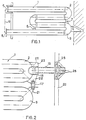
- the heating body 1 with a double pin 2, 3 is made of stainless steel. It is traversed by hot gases from a burner disposed at one end 4 which are discharged at the other end 5 according to the embodiment belonging to the state of the art illustrated in Figure 1. Organs of spacing (6, 7) avoid contact of two tubular elements during expansion.
- a third support 8 housed in the outer wall of the oven keeps the heating body in balance so that it does not sag at high temperatures while allowing sliding due to expansion.
- This arrangement has the disadvantage that accidentally high temperatures cause microwelds, in particular in point 7. Consequently, the upper tube is no longer free in its expansion, which causes it to swell and therefore to shift in relation to the burner flame. .
- the part of the support 8 integral with the oven deforms and causes the heating body to buckle over the height 9.
- FIG. 2 the support 7 of the heating body 1 which is provided in the case of FIG. 1, is replaced by a connecting rod 17.
- the support 18 advantageously slides on a support arm 19, preferably of stainless steel 25/20 or 37/18, rigidly fixed in the outer wall 20 of the oven.
- This support 18 is formed so as to allow movement in the direction of the support arm 19 and in directions perpendicular to the support arm 19 by means of a play advantageously chosen.
- the connecting rod 17 fixed by pivots between the gussets 21 and 22 makes the lower pin integral with the upper pin by allowing movements due to thermal expansion.
- the sliding support in the form of a cup 18, preferably made of stainless steel 25/20 or 37/18, is welded to the pin and held by the gussets 22 and 23.
- the support arm 19 is preferably tubular, closed at its inner end by a welded pad 28 and fixed to the wall 20 of the furnace by means of an anchoring device 25. In order to reduce the thermal bridges, it is stuffed with '' a wadded thermal insulator (rock wool, etc.).
- the device of the invention still has additional advantages.
- This new device can be easily placed and possibly replaced from outside the oven, using conventional tools.
- the support arm can be equipped with a gauge 26 consisting for example of a 25 x 5 mm square dish which indicates the behavior of this support, inside the oven from the outside of the latter.
- the device of the invention makes it possible to allow all of the expansion towards the interior of the oven. Consequently, the end 4 of the upper tube can be welded to its base plate; this avoids the use of complicated systems, often used by. manufacturers, for fixing the burners.
- the device of the invention therefore makes the oven more efficient, without however increasing its price.
- the installation and maintenance service can save a lot of time due to the simplicity of installation and easy access.
Landscapes
- Engineering & Computer Science (AREA)
- Chemical & Material Sciences (AREA)
- Mechanical Engineering (AREA)
- General Engineering & Computer Science (AREA)
- Materials Engineering (AREA)
- Crystallography & Structural Chemistry (AREA)
- Physics & Mathematics (AREA)
- Metallurgy (AREA)
- Organic Chemistry (AREA)
- Combustion & Propulsion (AREA)
- Thermal Sciences (AREA)
- Heat Treatment Of Articles (AREA)
- Heat Treatments In General, Especially Conveying And Cooling (AREA)
- Heat Treatment Of Strip Materials And Filament Materials (AREA)
- Gas Burners (AREA)
Description
- La présente invention concerne des supports améliorés destinés en particulier aux corps de chauffe de fours de recuit.
- Les corps de chauffe sont utilisés notamment dans des fours assurant en continu le recuit de bandes d'acier.
- Dans de tels fours, une bobine de bande d'acier est déroulée et la bande d'acier passe dans un dispositif de dégraissage. Elle est séchée par air chaud, avant de pénétrer dans le four qui est partagé en une section de chauffe et en une section de maintien. Il y règne une atmosphère neutre et une pression supérieure à la pression atmosphérique afin d'éviter tout risque de contamination. La bande est guidée au cours de son trajet dans le four entre les parois constituées par des corps de chauffe disposés en quinconce. En sortant du four, cette bande recuite est enroulée sur une bobine.
- Par l'article dans « Gaz dl'aujourd'hui•, volume 98, n° 9, septembre 1974, Paris (FR), intitulé « Une utilisation rationnelle de l'énergie : le tube radiant à gaz par MM. Douspis, pages 395 à 400, on connaît plusieurs types de tubes radiants (corps de chauffe), à savoir les tubes droits, les tubes en épingle simple et les tubes à recirculation.
- D'autres documents comme le brevet aux Etats-Unis d'Amérique n° 2822798 présentent des manières de fixation de tubes radiants droits et les documents GB-A-487 764 et FR-A-861 541 donnent des corps de chauffe particuliers ou de forme particulière.
- Le document GB-A-1 396796 concerne un moyen de support de tubes radiants en U, qui consiste en un galet fixé à la paroi du four, sur lequel le tube peut glisser sans frottement lors de la dilatation thermique.
- Ce moyen présente l'inconvénient d'être encombrant et de ne pouvoir être utilisé dans des fours assurant en continu le recuit de bandes d'acier, par exemple.
- Le document US-A-2652037 concerne des supports de corps de chauffe (tubes radiants) en forme de double épingle supportés par un simple appui fixé dans un tube perpendiculaire au tube radiant. Dans ce cas d'application, la dilatation du tube radiant provoque un glissement sur les appuis qui est cause d'usure, de micro-soudures, ... etc. En outre, les tubes dans lesquels sont fixés les appuis sont encombrants et empêchent le passage en continu d'une bande d'acier qui contourne des tubes radiants disposés en quinconce.
- Le document US-A-2204144 concerne des corps de chauffe en double épingle supportés ou suspendus et espacés par des organes permettant la dilatation de l'ensemble et servant de points de glissement qui permettent ainsi un mouvement relatif d'un élément du corps de chauffe par rapport à l'autre..
- Cependant, bien que le constructeur indique une température limite d'environ 840 °C pour le tube, on enregistre régulièrement une température d'ambiance dans le four de l'ordre de 930 °C ou même exceptionnellement de 1 040 °C.
- Cette allure excessive peut résulter d'une vitesse trop grande de déroulement de la bande, d'une qualité de produit pour laquelle les vitesses de la chauffe n'ont pas été prévues, d'une irrégularité des fréquences d'entretien qui laisse le four amputé d'une partie de sa capacité de chauffe.
- Dans ces conditions, on observe les inconvénients suivants :
- les systèmes généralement utilisés pour permettre la dilatation de l'ensemble, qui consistent en des organes d'espacement servant également de points de glissement qui permettent ainsi un mouvement relatif d'un élément de tube par rapport à l'autre, ne remplissent plus leur rôle. On constate surtout un grippage au niveau du point de glissement supportant l'épingle supérieure dû à des microsoudures engendrées surtout par une température trop élevée. Il y a alors gonflement du tube supérieur du corps de chauffe en épingle qui provoque un décentrement de la flamme du brûleur.
- Par suite d'une température trop élevée, l'appui solidaire de la paroi extérieure du four se déforme et introduit un couple qui provoque le flambage du corps de chauffe.
- Un couple semblable peut également être engendré par des tensions parasites créées lors de l'exécution des soudures des éléments tubulaires et des courbes qui seraient libérées lors de la première mise à feu du corps de chauffe et/ou après une réparation.
- La présente invention vise à apporter une solution à ces problèmes en fournissant un dispositif de support de corps de chauffe pour fours de recuit permettant la libre dilatation du corps de chauffe et éliminant totalement le risque de fluage de l'extrémité libre sans influencer défavorablement sa capacité de chauffe ni le bon fonctionnement du four. Ce support est formé en double épingle et traversé par des gaz chauds provenant d'un brûleur disposé à une extrémité et évacués par l'autre extrémité, le contact entre deux courbes de l'épingle étant évité par des organes d'espacement et un appui supplémentaire étant prévu dans la paroi extérieure du four et il est caractérisé en ce qu'il comporte à titre d'organe d'espacement une bielle reliant entre elles les deux courbes en épingle extérieures du corps de chauffe et à titre d'appui supplémentaire prévu dans la paroi extérieure du four un appui de l'épingle supérieure coulissant sur un bras support tubulaire fixé rigidement dans la paroi du four permettant des déplacements dans le sens de glissement de cet appui. La forme ronde de l'appui et du support permet le centrage automatique du corps de chauffe et le jeu important de ces pièces entre elles permet un placement très aisé.
- La bielle reliant les deux courbes en « épingle du corps de chauffe permet un mouvement relatif des éléments de tube entre eux et maintient par suspension l'épingle inférieure à l'épingle supérieure. Le point de glissement qui supportait l'épingle supérieure sur l'épingle inférieure est éliminé.
- Il est avantageux de souder des goussets adaptés à ladite bielle sur les deux courbes en épingle extérieures du corps de chauffe.
- Pour éviter le flambage dû à l'appui sur la paroi extérieure du four, on supporte le corps de chauffe par un appui soudé à sa partie supérieure et coulissant sur un bras support fixé rigidement dans la paroi du four. L'appui est choisi avantageusement de manière à permettre des déplacements dans le sens du bras support afin que le corps de chauffe ne soit soumis à de fortes contraintes.
- Le bras support est avantageusement tubulaire, est obturé à son extrémité intérieure par une pastille soudée et est bourré de préférence d'un isofant thermique ouateux ou autre.
- L'invention ainsi que son contexte seront mieux compris à l'aide des figures :
- la figure 1 montre le dispositif de support de l'état de la technique et
- la figure 2 montre un support suivant l'invention.
- Des repères de référence identiques seront utilisés pour des éléments identiques ou similaires dans les deux figures.
- Le corps de chauffe 1 en double épingle 2, 3 est en acier inoxydable. Il est traversé par des gaz chauds provenant d'un brûleur disposé à une extrémité 4 qui sont évacués à l'autre extrémité 5 selon la forme d'exécution appartenant à l'état de la technique illustrée à la figure 1. Des organes d'espacement (6, 7) évitent le contact de deux éléments tubulaires lors de la dilatation.
- Ils permettent également un glissement relatif des éléments tubulaires du corps de chauffe.
- Un troisième appui 8 logé dans la paroi extérieure du four maintient le corps de chauffe en équilibre pour qu'il ne s'affaisse pas aux hautes températures tout en permettant un glissement dû aux dilatations. Cette disposition a l'inconvénient que des températures accidentellement élevées engendrent des microsoudures, notamment au point 7. Par conséquent, le tube supérieur n'est plus libre dans sa dilatation ce qui entraîne son gonflement et donc un décentrement par rapport à la flamme du brûleur.
- Par suite d'une température trop élevée, la partie de l'appui 8 solidaire du four se déforme et provoque un flambage du corps de chauffe sur la hauteur 9.
- Dans une forme d'exécution conforme à l'invention (fig. 2) le support 7 du corps de chauffe 1 qui est prévu dans le cas de la figure 1, est remplacé par une bielle 17. L'appui 18 coulisse avantageusement sur un bras support 19, de préférence en acier inoxydable 25/20 ou 37/18, fixé rigidement dans la paroi extérieure 20 du four. Cet appui 18 est constitué de manière à permettre des déplacements dans le sens du bras support 19 et dans des sens perpendiculaires au bras support 19 moyennant un jeu avantageusement choisi.
- On a soudé sur les épingles en tube des goussets 21, 22 et 23, de préférence en acier inoxydable 25/20. La bielle 17 fixée par des pivots entre les goussets 21 et 22 rend l'épingle inférieure solidaire de l'épingle supérieure en autorisant les mouvements dus aux dilatations thermiques.
- L'appui coulissant, en forme de godet 18, de préférence en acier inoxydable 25/20 ou 37/18, est soudé sur l'épingle et maintenu par les goussets 22 et 23.
- Le bras support 19 est, de préférence tubulaire, obturé à son extrémité intérieure par une pastille soudée 28 et fixé à la paroi 20 du four au moyen d'un dispositif d'ancrage 25. Afin de diminuer les ponts thermiques, on le bourre d'un isolant thermique ouateux (laine de roche, etc.).
- En éliminant les inconvénients des autres systèmes, le dispositif de l'invention présente encore des avantages supplémentaires.
- Ce nouveau dispositif peut être placé aisément et éventuellement être remplacé depuis l'extérieur du four, à l'aide d'un outillage classique.
- On n'a pas besoin de maçons pour réaliser le montage. Le bras support peut être équipé d'une jauge 26 constituée par exemple d'un plat de 25 x 5 mm en équerre qui indique le comportement de ce support, à l'intérieur du four par l'extérieur de ce dernier.
- Le dispositif de l'invention permet de consentir la totalité de la dilatation vers l'intérieur du four. Par conséquent, on peut souder l'extrémité 4 du tube supérieur sur sa plaque de base ; on évite ainsi d'utiliser des systèmes compliqués, souvent employés par. les constructeurs, pour la fixation des brûleurs.
- Le dispositif de l'invention rend donc le four plus performant, sans toutefois augmenter son prix. Le service de montage et d'entretien peut gagner beaucoup de temps vu la simplicité de montage et l'accès facile.
Claims (7)
Priority Applications (1)
| Application Number | Priority Date | Filing Date | Title |
|---|---|---|---|
| AT83901180T ATE21122T1 (de) | 1982-03-26 | 1983-03-25 | Stuetzen fuer heizkoerper zum verwenden bei gluehoefen. |
Applications Claiming Priority (2)
| Application Number | Priority Date | Filing Date | Title |
|---|---|---|---|
| LU84040 | 1982-03-26 | ||
| LU84040A LU84040A1 (fr) | 1982-03-26 | 1982-03-26 | Supports ameliores de corps de chauffe de fours de recuit |
Publications (2)
| Publication Number | Publication Date |
|---|---|
| EP0105302A1 EP0105302A1 (fr) | 1984-04-18 |
| EP0105302B1 true EP0105302B1 (fr) | 1986-07-30 |
Family
ID=19729847
Family Applications (1)
| Application Number | Title | Priority Date | Filing Date |
|---|---|---|---|
| EP83901180A Expired EP0105302B1 (fr) | 1982-03-26 | 1983-03-25 | Supports ameliores de corps de chauffe destines aux fours de recuit |
Country Status (7)
| Country | Link |
|---|---|
| US (1) | US4520789A (fr) |
| EP (1) | EP0105302B1 (fr) |
| JP (1) | JPS59501270A (fr) |
| DD (1) | DD207977A5 (fr) |
| DE (1) | DE3364852D1 (fr) |
| LU (1) | LU84040A1 (fr) |
| WO (1) | WO1983003428A1 (fr) |
Families Citing this family (13)
| Publication number | Priority date | Publication date | Assignee | Title |
|---|---|---|---|---|
| BR8405390A (pt) * | 1983-10-21 | 1985-09-03 | Air Prod & Chem | Aparelho de aquecimento |
| FR2643447B1 (fr) * | 1989-02-17 | 1991-10-04 | Stein Heurtey | Systeme de tubes radiants pour fours de chauffage |
| US5845631A (en) * | 1997-08-21 | 1998-12-08 | Kerry Ingredients, Inc. | Heat exchanger for convection baking ovens |
| DE202008009065U1 (de) * | 2008-07-04 | 2008-10-09 | WS Wärmeprozesstechnik GmbH | Strahlungsheizanordnung mit Verzugkompensation |
| AT508264B1 (de) * | 2009-10-13 | 2010-12-15 | Ebner Ind Ofenbau | Vorrichtung zur wärmebehandlung von blechbändern |
| AT508368B1 (de) | 2009-10-13 | 2011-01-15 | Ebner Ind Ofenbau | Vorrichtung zur wärmebehandlung von blechbändern |
| PL2676093T3 (pl) | 2011-02-14 | 2019-01-31 | Massimiliano BISSON | Rurowy element promiennikowy dla urządzeń przemysłowych, jego zastosowanie i sposób obróbki cieplnej |
| WO2014072839A1 (fr) * | 2013-01-02 | 2014-05-15 | Bisson Massimiliano | Dispositif de support pour tubes radiants |
| JP6028595B2 (ja) * | 2013-01-29 | 2016-11-16 | 新日鐵住金株式会社 | ラジアントチューブを用いた加熱炉 |
| CN104152660B (zh) * | 2014-08-28 | 2016-05-18 | 航天精工股份有限公司 | 一种紧固件的局部退火定位装置 |
| BE1027839B1 (fr) * | 2019-12-10 | 2021-07-08 | Drever International Sa | Élément de chauffage radiant à extrémité libre |
| DE102020100748A1 (de) * | 2020-01-14 | 2021-07-15 | Loi Thermprocess Gmbh | Vorrichtung zum Abstützen von mindestens zwei Strahlheizrohren in einem Ofenraum sowie Industrieofen |
| CN117489876B (zh) * | 2024-01-02 | 2024-03-22 | 杭州万全金属软管有限公司 | 一种金属软管与燃气灶的连接结构 |
Family Cites Families (9)
| Publication number | Priority date | Publication date | Assignee | Title |
|---|---|---|---|---|
| US2204144A (en) * | 1935-10-31 | 1940-06-11 | Babcock & Wilcox Co | Fluid heat exchange apparatus |
| GB487764A (en) * | 1937-03-01 | 1938-06-24 | Surface Combustion Corp | Improvements in heat radiating combustion flues for furnaces |
| FR861541A (fr) * | 1938-11-15 | 1941-02-11 | Armco Sa | Perfectionnements aux appareils et dispositifs de chauffage industriel |
| US2200731A (en) * | 1938-11-15 | 1940-05-14 | Lee Wilson Sales Corp | Heating apparatus |
| US2652037A (en) * | 1947-09-03 | 1953-09-15 | Du Pont | Heat exchange apparatus |
| US2822798A (en) * | 1953-10-19 | 1958-02-11 | Harold N Ipsen | Burner tube assembly for heat treating furnaces |
| US3079910A (en) * | 1960-06-27 | 1963-03-05 | Bloom Eng Co Inc | Recuperative radiant tube burner mechanism |
| GB1396796A (en) * | 1972-07-21 | 1975-06-04 | Skoda Np | Heat radiating tube support |
| US3920383A (en) * | 1974-06-20 | 1975-11-18 | Electric Furnace Co | Fluted surface heat exchanger |
-
1982
- 1982-03-26 LU LU84040A patent/LU84040A1/fr unknown
-
1983
- 1983-03-25 JP JP58501275A patent/JPS59501270A/ja active Pending
- 1983-03-25 DE DE8383901180T patent/DE3364852D1/de not_active Expired
- 1983-03-25 EP EP83901180A patent/EP0105302B1/fr not_active Expired
- 1983-03-25 WO PCT/BE1983/000008 patent/WO1983003428A1/fr not_active Ceased
- 1983-03-25 US US06/560,984 patent/US4520789A/en not_active Expired - Lifetime
- 1983-03-28 DD DD83249262A patent/DD207977A5/de not_active IP Right Cessation
Also Published As
| Publication number | Publication date |
|---|---|
| DD207977A5 (de) | 1984-03-21 |
| LU84040A1 (fr) | 1983-11-17 |
| WO1983003428A1 (fr) | 1983-10-13 |
| EP0105302A1 (fr) | 1984-04-18 |
| JPS59501270A (ja) | 1984-07-19 |
| US4520789A (en) | 1985-06-04 |
| DE3364852D1 (en) | 1986-09-04 |
Similar Documents
| Publication | Publication Date | Title |
|---|---|---|
| EP0105302A1 (fr) | Supports ameliores de corps de chauffe destines aux fours de recuit. | |
| KR101548551B1 (ko) | 변형이 보상되는 복사 가열 장치 | |
| US10011887B2 (en) | Support device for radiant tubes | |
| FR2519748A1 (fr) | Module et garnissage d'isolation de la paroi interne d'un four, support d'element chauffant electrique pour ce module et procede de pose de modules d'isolation | |
| JP3549981B2 (ja) | 蓄熱交互燃焼式ラジアントチューブの炉内支持構造 | |
| JP3628858B2 (ja) | ラジアントチューブ支持装置 | |
| FR2488277A1 (fr) | Four pour le chauffage de metal et en particulier de profiles intermediaires avant leur laminage | |
| JP2005315510A (ja) | 加熱炉及び温度計並びに炉内温度制御方法 | |
| JP2010122232A (ja) | 加熱炉及び温度計 | |
| KR101867710B1 (ko) | 소둔로 | |
| KR102937905B1 (ko) | 연돌 내 이종 파이프간의 간격 유지 시스템 | |
| BE1027839B1 (fr) | Élément de chauffage radiant à extrémité libre | |
| JP3981629B2 (ja) | W型ラジアントチューブの支持構造 | |
| FR2463563A1 (fr) | Element de chauffage electrique a ailettes radiales | |
| KR100645929B1 (ko) | 열처리 장치의 히터 어셈블리 | |
| EP0546886A1 (fr) | Plaque de refroidissement pour unités métallurgiques, notamment pour hauts fourneaux | |
| JP4769842B2 (ja) | 高温用加熱炉 | |
| JPH0612380Y2 (ja) | 放熱管用スペーサ | |
| KR200382567Y1 (ko) | 열처리 장치의 히터 어셈블리 | |
| JPH02192590A (ja) | 加熱炉の炉内壁支持装置 | |
| EP0219482B1 (fr) | Four cloche | |
| KR0124765Y1 (ko) | 전기로용 히팅 엘리먼트 | |
| JP2018179327A (ja) | ラジアントチューブおよび熱処理炉 | |
| KR20060133505A (ko) | 열처리 장치의 히터 어셈블리 | |
| KR20100110789A (ko) | 고온 어닐링 로에서 시트 금속 조인트를 지지하는 장치 |
Legal Events
| Date | Code | Title | Description |
|---|---|---|---|
| PUAI | Public reference made under article 153(3) epc to a published international application that has entered the european phase |
Free format text: ORIGINAL CODE: 0009012 |
|
| AK | Designated contracting states |
Designated state(s): AT BE CH DE FR GB LI NL SE |
|
| 17P | Request for examination filed |
Effective date: 19840315 |
|
| GRAA | (expected) grant |
Free format text: ORIGINAL CODE: 0009210 |
|
| AK | Designated contracting states |
Kind code of ref document: B1 Designated state(s): AT BE CH DE FR GB LI NL SE |
|
| REF | Corresponds to: |
Ref document number: 21122 Country of ref document: AT Date of ref document: 19860815 Kind code of ref document: T |
|
| REF | Corresponds to: |
Ref document number: 3364852 Country of ref document: DE Date of ref document: 19860904 |
|
| PLBE | No opposition filed within time limit |
Free format text: ORIGINAL CODE: 0009261 |
|
| STAA | Information on the status of an ep patent application or granted ep patent |
Free format text: STATUS: NO OPPOSITION FILED WITHIN TIME LIMIT |
|
| 26N | No opposition filed | ||
| PGFP | Annual fee paid to national office [announced via postgrant information from national office to epo] |
Ref country code: DE Payment date: 19921130 Year of fee payment: 10 |
|
| PGFP | Annual fee paid to national office [announced via postgrant information from national office to epo] |
Ref country code: AT Payment date: 19930323 Year of fee payment: 11 |
|
| PGFP | Annual fee paid to national office [announced via postgrant information from national office to epo] |
Ref country code: NL Payment date: 19930331 Year of fee payment: 11 |
|
| PG25 | Lapsed in a contracting state [announced via postgrant information from national office to epo] |
Ref country code: DE Effective date: 19931201 |
|
| PGFP | Annual fee paid to national office [announced via postgrant information from national office to epo] |
Ref country code: CH Payment date: 19940310 Year of fee payment: 12 |
|
| PGFP | Annual fee paid to national office [announced via postgrant information from national office to epo] |
Ref country code: GB Payment date: 19940315 Year of fee payment: 12 |
|
| PGFP | Annual fee paid to national office [announced via postgrant information from national office to epo] |
Ref country code: SE Payment date: 19940317 Year of fee payment: 12 Ref country code: FR Payment date: 19940317 Year of fee payment: 12 |
|
| PG25 | Lapsed in a contracting state [announced via postgrant information from national office to epo] |
Ref country code: AT Effective date: 19940325 |
|
| PG25 | Lapsed in a contracting state [announced via postgrant information from national office to epo] |
Ref country code: NL Effective date: 19941001 |
|
| NLV4 | Nl: lapsed or anulled due to non-payment of the annual fee | ||
| EAL | Se: european patent in force in sweden |
Ref document number: 83901180.6 |
|
| PG25 | Lapsed in a contracting state [announced via postgrant information from national office to epo] |
Ref country code: GB Effective date: 19950325 |
|
| PG25 | Lapsed in a contracting state [announced via postgrant information from national office to epo] |
Ref country code: SE Effective date: 19950326 |
|
| PG25 | Lapsed in a contracting state [announced via postgrant information from national office to epo] |
Ref country code: LI Effective date: 19950331 Ref country code: CH Effective date: 19950331 |
|
| GBPC | Gb: european patent ceased through non-payment of renewal fee |
Effective date: 19950325 |
|
| PG25 | Lapsed in a contracting state [announced via postgrant information from national office to epo] |
Ref country code: FR Free format text: LAPSE BECAUSE OF NON-PAYMENT OF DUE FEES Effective date: 19951130 |
|
| REG | Reference to a national code |
Ref country code: CH Ref legal event code: PL |
|
| EUG | Se: european patent has lapsed |
Ref document number: 83901180.6 |
|
| REG | Reference to a national code |
Ref country code: FR Ref legal event code: ST |
|
| PGFP | Annual fee paid to national office [announced via postgrant information from national office to epo] |
Ref country code: BE Payment date: 20020118 Year of fee payment: 20 |
|
| BE20 | Be: patent expired |
Owner name: *COCKERILL SAMBRE Effective date: 20030325 |