EP0105405A2 - Serrure - Google Patents
Serrure Download PDFInfo
- Publication number
- EP0105405A2 EP0105405A2 EP83109355A EP83109355A EP0105405A2 EP 0105405 A2 EP0105405 A2 EP 0105405A2 EP 83109355 A EP83109355 A EP 83109355A EP 83109355 A EP83109355 A EP 83109355A EP 0105405 A2 EP0105405 A2 EP 0105405A2
- Authority
- EP
- European Patent Office
- Prior art keywords
- tumbler
- key
- face
- carrier
- tumblers
- Prior art date
- Legal status (The legal status is an assumption and is not a legal conclusion. Google has not performed a legal analysis and makes no representation as to the accuracy of the status listed.)
- Withdrawn
Links
Images


Classifications
-
- E—FIXED CONSTRUCTIONS
- E05—LOCKS; KEYS; WINDOW OR DOOR FITTINGS; SAFES
- E05B—LOCKS; ACCESSORIES THEREFOR; HANDCUFFS
- E05B29/00—Cylinder locks and other locks with plate tumblers which are set by pushing the key in
Definitions
- This invention relates to a lock comprising a hollow housing, a tumbler carrier mounted in the housing and formed with a keyway which extends into the tumbler carrier from one face thereof, called herein the outer end face, an aperture which intersects the keyway and is spaced from the outer end face, a tumbler disposed in the aperture and a resilient element engaged with the tumbler carrier and with the tumbler in a manner to urge the tumbler towards a locking position in which an end portion of the tumbler projects from the tumbler carrier into a recess in the housing, the tumbler also having a releasing position in which the end portion of the tumbler is not engageable with the housing and the tumbler carrier having guide faces for co-operation .witH the tumbler collectively to guide the tumbler for movement relative to the tumbler carrier along a path between the locking and releasing positions, and to restrain movement of the tumbler relative to the tumbler carrier transverse to said path.
- the invention also relates to a combination of the lock with a key which is insertable into the keyway of the tumbler housing to displace the tumbler to the releasing position.
- Locks known as disc tumbler locks are examples of locks of the kind referred to.
- a number of tumblers are provided in a lock of the kind referred to, each tumbler being disposed within its own aperture in the tumbler carrier and guided by respective guide faces of the tumbler carrier along a path which is parallel to the paths of movement of the other tumblers.
- the tumbler carrier is rotatable relative to the housing when the proper key is present in the keyway.
- locks in which the tumbler carrier is freed for displacement relative to the housing by insertion of the proper key and is always restrained against rotation relative to the housing fall within the scope of the invention.
- the tumblers are usually formed as substantially flat plates so that a relatively large number of tumblers can be accommodated in a tumbler housing of given length.
- the tumbler carrier For guiding each of these tumblers, there is provided in the tumbler carrier two pairs of flat, mutually opposed, parallel guide faces with the guide faces of one pair being perpendicular to those of the other pair.
- the resilient elements are generally arranged in two rows between which there lies a longitudinal axis of the tumbler housing, resilient elements engaged with alternate tumblers being disposed at opposite sides of the axis.
- the resilient element of a lock of the kind referred to, or each resilient element engaged with a corresponding tumbler is positioned centrally between the corresponding guide faces of the tumbler carrier.
- a centre of the resilient element lies substantially mid-way between respective planes defined by the guide faces. It will be understood that the resilient element itself may extend beyond these planes. In certain cases, the resilient element or the centre thereof may lie not directly between opposed guide faces but at a position which would be between the guide faces, if produced.
- a lock in accordance with the invention can conveniently be so arranged that the resilient element can co-operate properly with the tumbler when the tumbler is in either one of two alternative orientations which differ by rotation of the tumbler through 180° about an axis lying centrally between the guide faces.
- the tumbler has a first face which, when the key holds the tumbler in its releasing position against the action of the resilient element, rests on the key and exerts thereon a force derived from the resilient element.
- this first face preferably lies other than centrally between the guide faces, produced if necessary.
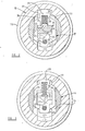
- the lock shown in Figures 1 to 4 comprises a housing 10 which may be of generally cylindrical form or may have some other external shape by which the housing is adapted to fit in a device which is to be controlled by the lock.
- a housing 10 which may be of generally cylindrical form or may have some other external shape by which the housing is adapted to fit in a device which is to be controlled by the lock.
- In the internal surface of the housing there are formed at diametrically opposite positions two grooves 11 and 12 which extend along the entire length of the housing, are rectilinear and are parallel to an axis 13 defined by the housing.
- a tumbler carrier 14 having at one end a head 15 which overlaps with an end face of the housing to prevent axial movement of the tumbler carrier relative to the housing in one direction. Relative axial movement in the opposite direction is prevented by an annular retainer 16 secured on the housing 10 and extending therefrom towards the axis 13 to overlap with a shoulder on the tumbler carrier which faces away from the head 15.
- An end portion of the tumbler carrier adjacent to the retainer 16 is adapted to drive a driven member of the controlled device.
- a pair of flats may be formed on this end portion or the end portion may be provided with an eccentric element or cam.
- a keyway extends through the interior of the tumbler carrier 14 from an outer end face 17 thereof, which is remote from the retainer 16, at least a part of the way towards an opposite end face of the tumbler carrier.
- the keyway extends to a bore 18 formed in the end portion of the tumbler carrier adjacent to the retainer.
- the keyway has a rectangular cross-section, as viewed in a direction along the axis 13.
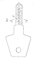
- the key for use with the lock has a shank 19 which is a sliding fit within the keyway and has two larger faces and two smaller faces.
- a free end portion 20 of the shank remote from a handle 21 of the key is of conical form.
- a number of apertures is provided in the tumbler carrier 14, each of these apertures extending through the tumbler carrier from a side thereof which is adjacent to the groove 11 to a side thereof adjacent to the groove 12, when the key is absent from the lock. These apertures are spaced apart along the axis 13. Each of these apertures has the same shape and dimensions and therefore only one of the apertures, indicated by the reference numeral 22, will be described.
- the aperture 22 is rectangular and is bounded by a first pair of guide faces, 23 and 24, which are flat, parallel to each other and perpendicular to the axis 13.
- the guide faces 23 and 24 are considerably larger than the guide faces 25 and 26.
- the guide faces 25 and 26 are spaced from and lie at opposite sides of the axis.
- the guide faces -23 and 24 are intersected by the keyway (which contains the axis 13), by a space 36 defined by the tumbler carrier for containing springs hereinafter mentioned and by a further space 37 extending from the keyway to the circumference of the tumbler carrier at a position remote from the space 36.
- each of the apertures formed in the tumbler carrier to intersect the keyway there is disposed a respective tumbler.
- the tumbler occupying the aperture 22 is indicated by the reference numeral 27.
- This tumbler is guided by the guide faces 23 to 26 for movement along a path which is perpendicular to the axis 13 and extends between the grooves 11 and 12 when the key is absent from the lock.
- the tumbler has opposite end portions 28 and 29 which can be received in the grooves 11 and 12 respectively.
- the other tumblers are arranged in a corresponding manner and have associated springs also arranged in a corresponding manner. It will be noted that all of the tumblers are urged by their springs towards the groove 11.
- the tumbler 27 defines a central opening 31, a part of which is occupied by the spring 30.
- the spring bears against a boundary of the opening near to the groove 11 and also bears against shoulders provided on the tumbler housing 14 adjacent to the tumbler 27 and facing generally towards the groove 11.
- a further opening is formed in the tumbler 27 at a position near to the end portion 29. Through this opening there extends a bar 32 which also extends through corresponding openings in the other tumblers. It will be seen that the bar 32 is a close fit in the tumbler 27 so that when the tumbler is displaced relative to the tumbler housing, the bar moves with the tumbler. As shown, a further one of the tumblers may also receive the bar with a close fit to provide good control over movement of the bar. However, the remaining tumblers receive the bar in somewhat larger openings so that limited movement of these tumblers relative to the bar is permitted.
- the axis 13 extends through the opening 31.
- the tip of the conical end portion 20 travels along the axis 13 and therefore enters the central opening of the tumbler.
- the conical surface of the key shank engages a surface 33 of the tumbler which forms a part of the boundary of the opening 31. Sliding of the end portion 20 of the key shank on the surface 33 drives the tumbler from the groove 11 towards the groove 12 by a camming action.
- a further surface 34 on the tumbler which also forms a part of the boundary of the opening 31, comes to rest on a location surface 35 of the key so positioned in relation to the axis 13 that the tumbler occupies its releasing position, in which the entire tumbler lies within the tumbler carrier 14 and the end portions 28 and 29 cannot engage the housing 10.
- the tumbler 27 can be received between the guide surfaces 23 to 26 in either one of two alternative orientations which differ by rotation of the tumbler through 180° about an axis perpendicular to the axis 13 and parallel to each of the guide faces. Since the surface 34 of the tumbler does not lie centrally between the guide faces, the position of this surface differs between these two orientations.
- the location surface 35 of the key lies in a recess formed in one of the larger faces of the key and extending from one of the smaller faces a part of the way towards the opposite smaller face. Thus, the position of the location surface corresponds to the position of the surface 34 of the tumbler when the key is fully inserted and the tumbler has one of its alternative orientations.
- the fully inserted key would not hold the tumbler in its releasing position.
- the surface 34 of the tumbler may then bear on an un-recessed part of a major face of the key shank so that the tumbler is held in a position in which the end portion 29 extends into the groove 12.
- Location surfaces are provided on the key for each of the tumblers.
- the key may be a double-entry key, in which case there is provided at each of the larger faces of the key shank a respective location surface for all of the tumblers.
- Each location surface is formed by moving a cutting tool in a direction parallel to the larger faces of the key and perpendicular to the smaller faces of the key towards and beyond one of the smaller faces a part of the way towards the other smaller face.
- the shape of the cutting tool and its position relative to the key shank is selected according to the required position of the location surface concerned.
- the bar 32 is intended to permit operation of the lock by a master key capable of moving to their releasing positions those tumblers in which the bar is received with a close fit.
- the arrangement is such that the bar then necessarily moves each of the other tumblers to its releasing position.
- Within or adjacent to the head 15 of the tumbler carrier there may be provided in the keyway an obstruction which prevents insertion of certain keys into the lock whilst permitting the insertion of other keys having an appropriate groove in the key shank to provide clearance for the obstruction.
- the position of the obstruction may vary as between different samples of the lock so that a slave key which can be inserted in one lock cannot be inserted in another but a master key can be inserted into both.
- the lock may be modified by omission of the bar 32 and arrangement of alternate springs at opposite sides of the axis of the lock.
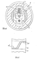
- a tumbler 40 provided with a spring 41 for urging the tumbler in the upwards direction, as shown in the drawing.
- a tumbler 42 Adjacent to the tumbler 40, there is a tumbler 42 provided with a spring 43 for urging the tumbler 42 downwards, as shown in the drawing.
- each of the springs 41 and 43 is disposed at that side of the axis of the lock, away from which the spring urges the associated tumbler.
- the tumbler 42 is illustrated in Figure 8, where it can be seen that the tumbler has an opening 44 for receiving the spring 43 and which is separate from the central opening 45 of the tumbler.
- the tumbler has a face 46 which forms a part of the boundary of the central opening 45 and which engages a corresponding location surface on the key.
- the opening 44 lies mid-way between lateral margins of the tumbler; whereas the surface 46 lies near to one lateral margin and remote from the other lateral margin.
- the centre of the opening 44 lies - , centrally between guide faces of the lock which guide the tumbler 42; whereas the surface 46 lies much nearer to one guide face of the lock than to an opposite guide face.
- a further part of the boundary of the opening 45 is defined by a surface 48 which faces in the same direction as does the surface 46, that is away from the opening 44, and which extends from the vicinity of the surface 46 to an opposite lateral boundary of the opening 45.
- a part of the surface 48 lies centrally between the guide faces of the body with which the tumbler engages and is aligned with the longitudinal centreline of the opening 44, and therefore with the centreline of the spring 43 received in that opening.
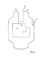
- the tumbler shown in Figure 8 is first engaged by the face 49 on the end portion of the key, this face engaging the face 48 of the tumbler over a region which, in substance, includes the axis of the associated spring 43.
- the surface 48 of the tumbler slides on the face 49 of the key and then. onto a face of the key which is parallel to the direction of movement of the key. In this way, the tumbler is moved a part of the way towards its releasing position.
- the face 52 of the key then engages the surface 46 of the tumbler and continued movement of the key along the lock causes the tumbler to move into or through its releasing position, the surface 48 of the tumbler then being raised clear of the key.
- the position of the tumbler is determined by engagement of the surface 46 with a corresponding location surface on the key. It will be noted that the releasing position of the key will not be affected by wear of the surface 48 which is subjected to the initial sliding contact between the tumbler and key upon insertion of the key.
- each aperture of the tumbler carrier which receives one of the tumblers is bridged by a part of the body with which one end portion of the associated spring is engaged.
- the part of the body which bridges the aperture containing the tumbler 42 is indicated by the reference numeral 54.
- the bridging part 54 of the tumbler carrier enters the opening 44 and reduces the risk of deformation of the limbs '55 and 56 of the tumbler which lie on opposite sides of the opening 44.
- the bridging parts of the tumbler carrier support the tumblers and contribute significantly to the strength of the tumbler carrier.
- the tumbler 42 is generally flat. However, adjacent to one lateral margin, this tumbler includes an outstanding portion 47 which is bent somewhat with respect to the remainder of the tumbler and departs from the generally flat condition of the tumbler.
- Each tumbler of the modified lock is provided with a similar outstanding portion.
- the outstanding portions of those tumblers with springs at the same side of the axis of the lock form a single, substantially rectilinear row, when the tumblers are in their releasing positions and the outstanding portions of the tumblers with springs at the opposite side of'the axis of the lock form a second substantially rectilinear row.
- the 'outstanding portions of the tumblers can readily be sensed by fingers of a person assembling the lock or by a machine which assembles the lock, to assist in establishing the required orientation of the tumblers.
- each recesses extend more than half of the way across a respective larger face of the key shank from a respective smaller face towards the opposite smaller face.
- a sinuous rib which extends along the key shank between the recesses and which engages the tumblers during movement of the key into and out of the lock.
- each recess may extend from a respective smaller face less than half of the way across a respective larger face towards the opposite smaller face, thereby leaving a rectilinear central rib on the larger face, the rib having spurs which extend to respective smaller faces of the shank.
Landscapes
- Physics & Mathematics (AREA)
- Electromagnetism (AREA)
- Lock And Its Accessories (AREA)
- Buckles (AREA)
Applications Claiming Priority (2)
| Application Number | Priority Date | Filing Date | Title |
|---|---|---|---|
| GB8228184 | 1982-10-01 | ||
| GB8228184 | 1982-10-01 |
Publications (2)
| Publication Number | Publication Date |
|---|---|
| EP0105405A2 true EP0105405A2 (fr) | 1984-04-18 |
| EP0105405A3 EP0105405A3 (fr) | 1984-09-05 |
Family
ID=10533337
Family Applications (1)
| Application Number | Title | Priority Date | Filing Date |
|---|---|---|---|
| EP83109355A Withdrawn EP0105405A3 (fr) | 1982-10-01 | 1983-09-20 | Serrure |
Country Status (4)
| Country | Link |
|---|---|
| EP (1) | EP0105405A3 (fr) |
| AU (1) | AU1923783A (fr) |
| GB (1) | GB2127891A (fr) |
| ZA (1) | ZA837070B (fr) |
Cited By (1)
| Publication number | Priority date | Publication date | Assignee | Title |
|---|---|---|---|---|
| ES2127042A1 (es) * | 1994-01-14 | 1999-04-01 | Huwil Werke Gmbh | Cilindro de plaquitas. |
Families Citing this family (1)
| Publication number | Priority date | Publication date | Assignee | Title |
|---|---|---|---|---|
| US4561270A (en) * | 1983-12-07 | 1985-12-31 | Briggs & Stratton Corp. | Key operated shallow penetration lock |
Family Cites Families (8)
| Publication number | Priority date | Publication date | Assignee | Title |
|---|---|---|---|---|
| DE327599C (de) * | 1918-08-12 | 1920-10-14 | Antoine Andreani | Stechschluesselschloss |
| DE627773C (de) * | 1933-12-13 | 1936-03-23 | Bauer A G | Zylinderschloss mit flachem Stechschluessel |
| GB864968A (en) * | 1958-05-23 | 1961-04-12 | Gen Motors Corp | Improvements in key-operable tumbler locks |
| GB945792A (en) * | 1960-03-03 | 1964-01-08 | Parkes Josiah & Sons Ltd | Improvements in or relating to pin tumbler mechanism for pin tumbler locks or latches |
| DE1953323A1 (de) * | 1969-10-23 | 1971-05-06 | Eduard Ubrig & Soehne Gmbh | Zylinderschloss mit Plaettchen-Zuhaltungen |
| FR2343108A1 (fr) * | 1976-03-01 | 1977-09-30 | Neiman Sa | Serrure de surete a pistons, procede et dispositif pour sa fabrication |
| EP0069887B1 (fr) * | 1981-07-11 | 1985-12-04 | Neiman S.A. | Serrure cylindrique à gorges montées en paires |
| GB2107380A (en) * | 1981-09-23 | 1983-04-27 | Lowe & Fletcher Ltd | Cylinder lock |
-
1983
- 1983-09-16 GB GB08324868A patent/GB2127891A/en not_active Withdrawn
- 1983-09-19 AU AU19237/83A patent/AU1923783A/en not_active Abandoned
- 1983-09-20 EP EP83109355A patent/EP0105405A3/fr not_active Withdrawn
- 1983-09-22 ZA ZA837070A patent/ZA837070B/xx unknown
Cited By (1)
| Publication number | Priority date | Publication date | Assignee | Title |
|---|---|---|---|---|
| ES2127042A1 (es) * | 1994-01-14 | 1999-04-01 | Huwil Werke Gmbh | Cilindro de plaquitas. |
Also Published As
| Publication number | Publication date |
|---|---|
| EP0105405A3 (fr) | 1984-09-05 |
| GB8324868D0 (en) | 1983-10-19 |
| GB2127891A (en) | 1984-04-18 |
| ZA837070B (en) | 1984-06-27 |
| AU1923783A (en) | 1984-04-05 |
Similar Documents
| Publication | Publication Date | Title |
|---|---|---|
| US5765417A (en) | Free wheel lock cylinder | |
| EP0416500B1 (fr) | Serrure cylindrique et clef | |
| US8099988B1 (en) | Tool-less rekeyable lock cylinder | |
| EP0413772B1 (fr) | Mecanisme de retenue d'une piece d'extremite | |
| US20120247163A1 (en) | Rekeyable lock cylinder having rotatable key followers | |
| US5420385A (en) | Key operable safety switch | |
| EP1468153B1 (fr) | Serrure de haute securité et combinaison haute securité de serrure et de cle | |
| JP2905381B2 (ja) | キーブランク及びキー | |
| US4478061A (en) | Cylinder lock | |
| CA2495269C (fr) | Ensemble serrure a possibilite de changement de cle et procede de fonctionnement | |
| US5724841A (en) | Key and cylinder lock unit | |
| US7716960B2 (en) | Lock device | |
| US20090031774A1 (en) | Rekeyable lock cylinder | |
| US4658105A (en) | Electrical contact means for a lock cylinder with an electronic/mechanical key | |
| AU2003238098A1 (en) | High security lock and key blade combination | |
| GB2173852A (en) | Cylinder lock - key - combination | |
| US5703339A (en) | Safety switch | |
| EP0291220B1 (fr) | Mécanisme d'accouplement pour serrures à barillet double | |
| US6125674A (en) | System consisting of a noncopyable key and a closed cylinder for same | |
| EP0105405A2 (fr) | Serrure | |
| EP0721035B1 (fr) | Unité de clé et serrure cylindrique | |
| CZ43194A3 (en) | Cylindrical lock with a flat key | |
| EP0065813B1 (fr) | Serrure cylindrique | |
| EP3103944A1 (fr) | Clé avec un élément pivotant et un verrou | |
| EP0871188B2 (fr) | Interrupteur de sécurité à clé |
Legal Events
| Date | Code | Title | Description |
|---|---|---|---|
| PUAI | Public reference made under article 153(3) epc to a published international application that has entered the european phase |
Free format text: ORIGINAL CODE: 0009012 |
|
| AK | Designated contracting states |
Designated state(s): AT BE CH DE FR GB IT LI LU NL SE |
|
| PUAL | Search report despatched |
Free format text: ORIGINAL CODE: 0009013 |
|
| AK | Designated contracting states |
Designated state(s): AT BE CH DE FR GB IT LI LU NL SE |
|
| STAA | Information on the status of an ep patent application or granted ep patent |
Free format text: STATUS: THE APPLICATION IS DEEMED TO BE WITHDRAWN |
|
| 18D | Application deemed to be withdrawn |
Effective date: 19850506 |
|
| RIN1 | Information on inventor provided before grant (corrected) |
Inventor name: HERRIOTT, LESLIE VICTOR |