EP0105450A2 - Dispositif de montage de tuyaux hydrauliques pour ensemble de mât à visibilité élevée - Google Patents
Dispositif de montage de tuyaux hydrauliques pour ensemble de mât à visibilité élevée Download PDFInfo
- Publication number
- EP0105450A2 EP0105450A2 EP83109624A EP83109624A EP0105450A2 EP 0105450 A2 EP0105450 A2 EP 0105450A2 EP 83109624 A EP83109624 A EP 83109624A EP 83109624 A EP83109624 A EP 83109624A EP 0105450 A2 EP0105450 A2 EP 0105450A2
- Authority
- EP
- European Patent Office
- Prior art keywords
- assembly
- hoses
- upright
- mast
- mast assembly
- Prior art date
- Legal status (The legal status is an assumption and is not a legal conclusion. Google has not performed a legal analysis and makes no representation as to the accuracy of the status listed.)
- Granted
Links
Images


Classifications
-
- B—PERFORMING OPERATIONS; TRANSPORTING
- B66—HOISTING; LIFTING; HAULING
- B66F—HOISTING, LIFTING, HAULING OR PUSHING, NOT OTHERWISE PROVIDED FOR, e.g. DEVICES WHICH APPLY A LIFTING OR PUSHING FORCE DIRECTLY TO THE SURFACE OF A LOAD
- B66F9/00—Devices for lifting or lowering bulky or heavy goods for loading or unloading purposes
- B66F9/06—Devices for lifting or lowering bulky or heavy goods for loading or unloading purposes movable, with their loads, on wheels or the like, e.g. fork-lift trucks
- B66F9/075—Constructional features or details
- B66F9/20—Means for actuating or controlling masts, platforms, or forks
- B66F9/205—Arrangements for transmitting pneumatic, hydraulic or electric power to movable parts or devices
Definitions
- This invention relates generally to a mast assembly for a lift truck and more particularly to a mounting arrangement for hydraulic hoses employed on a mast assembly to provide it with a high degree of operator visibility.
- Special attachments or work tools for lift trucks are generally attached on a carriage assembly thereof.
- the carriage assembly is slidably mounted on a movable upright assembly which is, in turn, slidably mounted on a fixed upright assembly.
- the special attachments may take the form of a rotating carriage, a load push-pull, or a carton, bale, paper roll, barrel, or general purpose clamp.
- the special attachment generally includes a plurality of hydraulic cylinders adapted to be selectively actuated under control of an operator. It is highly desirable to provide a routing arrangement for the hydraulic hoses, interconnected between the cylinders and the operator control station, that affords the operator with a maximum degree of forward visibility.
- Conventional routing arrangements normally include a plurality of sheaves and brackets for mounting and guiding the hoses on the mast assembly with opposite ends of the hoses being interconnected between a manifold, secured on the fixed upright assembly, and a bracket, secured on the carriage assembly.
- the bracket carries fittings thereon, adapted for connection to the actuating cylinders for the special attachment.
- routing arrangement of this type provide adequate protection to the hoses and permit relative movement between the upright assemblies and carriage without unduly stressing the hoses.
- the present invention is directed to overcoming one or more of the problems as set forth above.
- a mast assembly comprises a fixed upright assembly, a movable upright assembly slidably mounted on the fixed upright assembly, a carriage assembly slidably mounted on the movable upright assembly, and a plurality of flexible hoses attached between the fixed upright assembly and the carriage assembly.
- This invention is directed to an improved routing arrangement for the hoses wherein a loop portion of each hose is positioned adjacent to a lower end of an inner upright of the movable upright assembly and means for mounting and guiding the loop portions of the hoses on the inner upright in vertically spaced and closely compacted relationship relative to each other and for permitting movement of the movable upright assembly relative to the hoses.
- the improved routing arrangement of this invention provides the operator of a lift truck or other type of industrial vehicle with a high degree of forward visibility through the mast assembly.
- the routing arrangement is compact, protects the hoses against damage, and permits relative movement between the upright assemblies and carriage without unduly stressing the hoses.
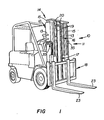
- FIG. 1 illustrates a lift truck 10 having a mast assembly 11 mounted forwardly thereon in a conventional manner.
- the mast assembly includes an outer or fixed upright assembly 12, suitably mounted on a frame of the lift truck and having a pair of laterally-spaced uprights 13 secured together by transverse tie bars.
- An inner or movable upright assembly 14, including a pair of laterally-spaced uprights 15, is slidably mounted on the fixed upright assembly to be selectively raised and lowered thereon by a lift system 16 including a lift cylinder 17 attached between the fixed and movable upright assemblies.
- a carriage assembly 18 is slidably mounted on the movable upright assembly and is adapted to be selectively moved thereon by chains 19, attached between the fixed upright and carriage assemblies and entrained over sheaves 20 mounted on the movable upright assembly.
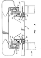
- a plurality of flexible hoses 21 are attached between fixed upright assembly 12 and the carriage assembly and terminate at snubbed-off fittings 22 ( Figure 2), adapted for connection to standard hydraulic cylinders utilized to selectively actuate a special attachment mounted on the carriage assembly.
- a special attachment (not shown) can be substituted in lieu of standard forks 23 and may take the form of a rotating carriage, a load push-pull, or a carton, bale, paper roll, barrel, or general purpose clamp. Since these types of special attachments and their actuating cylinders are well known in the art, a further description thereof is unnecessary for a clear understanding of this invention.
- This invention is directed to a routing arrangement 24 adapted to compactly mount hoses 21 on the mast assembly to provide the operator of the lift truck with a high degree of forward visibility through the mast assembly.
- the flexible hoses define a single loop portion 25 positioned adjacent to a lower end 26 of a respective upright 15 of the movable upright assembly. Since routing arrangement 24 is duplicated on each side of the mast assembly, only one of the routing arrangements will be described in detail with duplicate numerals depicting corresponding components and constructions of the other routing arrangement.
- Each routing arrangement 24 includes means 27 for mounting and guiding loop portions 25 of the flexible hoses on a respective inner upright 15 in vertically spaced and closely compacted relationship relative to each other and for permitting vertical movements of movable upright assembly 14 relative to the hoses.
- such means 27 includes three sheaves 28 rotatably mounted in vertically spaced relationship on lower end 24 of upright 15. As shown in Figure 2, the lowest or first loop portion 25a of the loop portions is entrained under a lower or first sheave 28a and a second loop portion 25b is entrained under an intermediate or second sheave 28b and between the first and second sheaves. The upper or third loop portion 25c is entrained under the upper or third sheave 28c and between the second and third sheaves.
- First and second sheaves 28a and 28b are thus mounted closely adjacent to each other and capture second loop portion 25b therebetween to prevent displacement of the loop portion from the sheaves. Likewise, first loop portion 25a is held under first sheave 28a whereas third loop portion 25c is captured between second and third sheaves 28b and 28c, respectively.
- fittings 22, adapted for attachment to the actuating cylinders of the special attachment mounted on the carriage assembly, are suitably attached on a bracket 29, secured forwardly on an upright member 30 of the carriage assembly.
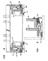
- the hoses extend upwardly from sheaves 28 in substantial parallel relationship relative to each other and further extend through a slot 31, formed through member 30.
- a clip 32 is attached to an inboard side of member 30, adjacent to slot 31, to retain and align upper portions of the hoses on the member.
- the hose portions on the opposite side of sheaves 28 extend upwardly in substantial parallel relationship and are captured and guided within a slotted bracket 33 having a generally U-shaped retaining portion, when viewed in cross-section, as shown in Figure 5.
- the bracket is suitably secured on an inboard side of fixed upright 13 and extends inwardly to ensure that the hoses are entrapped and guided therein.
- the hoses are connected at suitable fittings 34 to a plurality of rigid metallic conduits 35 to communicate hydraulic fluid from the operator control system on the lift truck (not shown) to fittings 22 and thus the special attachment cylinders (not shown) adapted to be connected thereto.
- the conduits are mounted on the fixed upright assembly by brackets 36, 37 and 38 and terminate at fittings 39, also secured on the fixed upright assembly by a bracket 40.
- fittings 39 are adapted - to be connected, via flexible hoses (not shown), to an operator control system for selectively communicating hydraulic fluid to fittings 22 (Figure 2).
- Mast assembly 11 finds particular application to industrial trucks, such as lift truck 10 illustrated in Figure 1.
- the lift truck is adapted to have lift forks 23 thereof replaced by a rotating carriage, a load push-pull, one of the various types of standard clamps, or other work tool comprising a special attachment for the lift truck.
- the attachment is suitably mounted on carriage assembly 18 and includes a plurality of hydraulic cylinders adapted to be connected to fittings 22 for selective actuation by the operator.
- Routing arrangement 24 ensures that hoses 21 are compactly positioned on the mast assembly and are substantially protected against damage and wear. As shown in Figure 2, routing arrangement 24 further ensures that the operator is accorded a high degree of forward visibility when operating the lift truck to thus ensure efficient operation of the attachment mounted on the carriage assembly.
- the invention may be summarized as follows:
Landscapes
- Engineering & Computer Science (AREA)
- Transportation (AREA)
- Structural Engineering (AREA)
- Chemical & Material Sciences (AREA)
- Combustion & Propulsion (AREA)
- Civil Engineering (AREA)
- Life Sciences & Earth Sciences (AREA)
- Geology (AREA)
- Mechanical Engineering (AREA)
- Forklifts And Lifting Vehicles (AREA)
Applications Claiming Priority (2)
| Application Number | Priority Date | Filing Date | Title |
|---|---|---|---|
| US06/432,584 US4503936A (en) | 1982-10-04 | 1982-10-04 | Hydraulic hose mounting arrangement for high-visibility mast assembly |
| US432584 | 1995-05-09 |
Publications (3)
| Publication Number | Publication Date |
|---|---|
| EP0105450A2 true EP0105450A2 (fr) | 1984-04-18 |
| EP0105450A3 EP0105450A3 (en) | 1985-04-24 |
| EP0105450B1 EP0105450B1 (fr) | 1987-11-19 |
Family
ID=23716769
Family Applications (1)
| Application Number | Title | Priority Date | Filing Date |
|---|---|---|---|
| EP83109624A Expired EP0105450B1 (fr) | 1982-10-04 | 1983-09-27 | Dispositif de montage de tuyaux hydrauliques pour ensemble de mât à visibilité élevée |
Country Status (4)
| Country | Link |
|---|---|
| US (1) | US4503936A (fr) |
| EP (1) | EP0105450B1 (fr) |
| CA (1) | CA1196314A (fr) |
| NO (1) | NO160503C (fr) |
Cited By (2)
| Publication number | Priority date | Publication date | Assignee | Title |
|---|---|---|---|---|
| FR2649388A1 (fr) * | 1989-07-04 | 1991-01-11 | Linde Ag | Chariots elevateurs industriels et guides de tube pour ces chariots |
| DE19903174A1 (de) * | 1999-01-27 | 2000-08-10 | Kaup Gmbh & Co Kg | Anbaugerät für Flurförderzeuge, mit einem Hubmast, insbesondere für Gabelstapler |
Families Citing this family (8)
| Publication number | Priority date | Publication date | Assignee | Title |
|---|---|---|---|---|
| JPS60103193U (ja) * | 1983-12-16 | 1985-07-13 | 株式会社豊田自動織機製作所 | フオ−クリフトにおけるアタツチメント用配管装置 |
| JPS60137797U (ja) * | 1984-02-23 | 1985-09-12 | 株式会社豊田自動織機製作所 | フルフリ−マスト式フオ−クリフトの荷役用油圧配管装置 |
| US5361874A (en) * | 1993-09-28 | 1994-11-08 | Brown Verbern R | Confined, single shaft wall elevator lifting system |
| DE102004040298A1 (de) * | 2004-08-19 | 2006-02-23 | Jungheinrich Ag | Flurförderzeug mit vergrößertem Fahrersichtfeld |
| JP4806985B2 (ja) * | 2005-07-15 | 2011-11-02 | 株式会社豊田自動織機 | 産業車両のリフト装置 |
| US9527711B2 (en) * | 2014-06-04 | 2016-12-27 | Jungheinrich Aktiengesellschaft | Lift frame for an industrial truck |
| USD902699S1 (en) | 2019-07-30 | 2020-11-24 | Hyster-Yale Group, Inc. | Hose termination bracket |
| CN113148897A (zh) * | 2021-04-29 | 2021-07-23 | 中国人民解放军海军航空大学 | 一种狭小空间下的转运提升装置 |
Family Cites Families (11)
| Publication number | Priority date | Publication date | Assignee | Title |
|---|---|---|---|---|
| US2724520A (en) * | 1951-11-16 | 1955-11-22 | Baker Raulang Co | Industrial truck |
| US2736445A (en) * | 1952-04-15 | 1956-02-28 | Yale & Towne Mfg Co | Flexible line guide for electric truck |
| US2791293A (en) * | 1953-11-02 | 1957-05-07 | Baker Raulang Co | Industrial truck |
| GB853882A (en) * | 1958-01-02 | 1960-11-09 | Lansing Bagnall Ltd | Improvements in or relating to goods handling trucks |
| US3208556A (en) * | 1962-02-19 | 1965-09-28 | Towmotor Corp | Multiple stage masts for lift trucks |
| US3166208A (en) * | 1962-08-24 | 1965-01-19 | Yale & Towne Inc | Hose guide arrangement |
| US3289869A (en) * | 1964-03-09 | 1966-12-06 | Clark Equipment Co | Hose mounting |
| BE661949A (fr) * | 1964-04-01 | |||
| US3462028A (en) * | 1967-06-12 | 1969-08-19 | Clark Equipment Co | Apparatus for reeving conduits in extendible uprights |
| US3777853A (en) * | 1972-04-05 | 1973-12-11 | Allis Chalmers | Hose guide for lift truck |
| US3968859A (en) * | 1974-12-23 | 1976-07-13 | Allis-Chalmers Corporation | Multiple hose guide arrangement for a lift truck |
-
1982
- 1982-10-04 US US06/432,584 patent/US4503936A/en not_active Expired - Fee Related
-
1983
- 1983-09-08 CA CA000436246A patent/CA1196314A/fr not_active Expired
- 1983-09-27 EP EP83109624A patent/EP0105450B1/fr not_active Expired
- 1983-10-03 NO NO833588A patent/NO160503C/no unknown
Cited By (3)
| Publication number | Priority date | Publication date | Assignee | Title |
|---|---|---|---|---|
| FR2649388A1 (fr) * | 1989-07-04 | 1991-01-11 | Linde Ag | Chariots elevateurs industriels et guides de tube pour ces chariots |
| DE19903174A1 (de) * | 1999-01-27 | 2000-08-10 | Kaup Gmbh & Co Kg | Anbaugerät für Flurförderzeuge, mit einem Hubmast, insbesondere für Gabelstapler |
| DE19903174C2 (de) * | 1999-01-27 | 2001-05-31 | Kaup Gmbh & Co Kg | Anbaugerät für Flurförderzeuge, mit einem Hubmast, insbesondere für Gabelstapler |
Also Published As
| Publication number | Publication date |
|---|---|
| US4503936A (en) | 1985-03-12 |
| NO160503B (no) | 1989-01-16 |
| EP0105450B1 (fr) | 1987-11-19 |
| CA1196314A (fr) | 1985-11-05 |
| EP0105450A3 (en) | 1985-04-24 |
| NO833588L (no) | 1984-04-05 |
| NO160503C (no) | 1989-04-26 |
Similar Documents
| Publication | Publication Date | Title |
|---|---|---|
| AU665909B2 (en) | Lift truck parallel arm clamp for compatibly maximizing operator visibility and load-carrying capacity | |
| CA1170294A (fr) | Vehicules de ferme tout usage | |
| US4261438A (en) | Lift truck mast having high visibility and extensibility | |
| US4503936A (en) | Hydraulic hose mounting arrangement for high-visibility mast assembly | |
| US2795346A (en) | Load grip side shift for lift trucks | |
| US4531615A (en) | High-visibility mast assembly for lift trucks | |
| EP1476389A1 (fr) | Ensemble de deplacement de fourche pour chariots elevateurs | |
| US4356893A (en) | Load lifting carriage and mast assembly | |
| ITTO980765A1 (it) | Veicolo utilizzabile come sollevatore a trattore agricolo. | |
| CA1089415A (fr) | Mecanisme a cylindres pour le deploiement d'un mat sur son chariot porteur | |
| US4630700A (en) | Adjustable operator cab on a motor-drive truck | |
| US4621711A (en) | Pressure oil line system for a fork lift truck | |
| US3894616A (en) | Forklift | |
| US4592449A (en) | Hydraulic power piping unit for a lift truck | |
| US6871425B2 (en) | Wing plow apparatus for attachment to a vehicle for carrying out a benching operation | |
| EP0050110A4 (fr) | Ensemble de chariot et de mat de levage de charge. | |
| CA1083089A (fr) | Circuit d'equipement relie a la pompe a bascule lente et rapide | |
| JP3348638B2 (ja) | フォークリフトトラックのマスト装置 | |
| GB2164319A (en) | Lifting frame for vehicle | |
| CA1140897A (fr) | Chariot transporteur-elevateur a mats | |
| CN112357838B (zh) | 一种叉车三级全自由工作装置的货叉调距油缸的管路系统 | |
| EP0199544A2 (fr) | Chariot élévateur à fourche | |
| EP0932730A1 (fr) | Dispositif amortisseur pour machines mobiles | |
| JPH0940390A (ja) | 三段マスト式フォークリフトの油圧配管装置 | |
| JPH11116195A (ja) | フォークリフトトラックのマスト装置 |
Legal Events
| Date | Code | Title | Description |
|---|---|---|---|
| PUAI | Public reference made under article 153(3) epc to a published international application that has entered the european phase |
Free format text: ORIGINAL CODE: 0009012 |
|
| AK | Designated contracting states |
Designated state(s): FR GB SE |
|
| PUAL | Search report despatched |
Free format text: ORIGINAL CODE: 0009013 |
|
| 17P | Request for examination filed |
Effective date: 19850102 |
|
| AK | Designated contracting states |
Designated state(s): FR GB SE |
|
| 17Q | First examination report despatched |
Effective date: 19860210 |
|
| RAP1 | Party data changed (applicant data changed or rights of an application transferred) |
Owner name: CATERPILLAR INDUSTRIAL INC. |
|
| GRAA | (expected) grant |
Free format text: ORIGINAL CODE: 0009210 |
|
| AK | Designated contracting states |
Kind code of ref document: B1 Designated state(s): FR GB SE |
|
| ET | Fr: translation filed | ||
| PLBE | No opposition filed within time limit |
Free format text: ORIGINAL CODE: 0009261 |
|
| STAA | Information on the status of an ep patent application or granted ep patent |
Free format text: STATUS: NO OPPOSITION FILED WITHIN TIME LIMIT |
|
| 26N | No opposition filed | ||
| PGFP | Annual fee paid to national office [announced via postgrant information from national office to epo] |
Ref country code: FR Payment date: 19900809 Year of fee payment: 8 |
|
| PGFP | Annual fee paid to national office [announced via postgrant information from national office to epo] |
Ref country code: GB Payment date: 19900814 Year of fee payment: 8 |
|
| PGFP | Annual fee paid to national office [announced via postgrant information from national office to epo] |
Ref country code: SE Payment date: 19900904 Year of fee payment: 8 |
|
| PG25 | Lapsed in a contracting state [announced via postgrant information from national office to epo] |
Ref country code: GB Effective date: 19910927 |
|
| PG25 | Lapsed in a contracting state [announced via postgrant information from national office to epo] |
Ref country code: SE Effective date: 19910928 |
|
| GBPC | Gb: european patent ceased through non-payment of renewal fee | ||
| PG25 | Lapsed in a contracting state [announced via postgrant information from national office to epo] |
Ref country code: FR Effective date: 19920529 |
|
| REG | Reference to a national code |
Ref country code: FR Ref legal event code: ST |
|
| EUG | Se: european patent has lapsed |
Ref document number: 83109624.3 Effective date: 19920408 |