EP0105496A2 - Verfahren und Vorrichtung zur genauen Zuführung von Fluidmischungen - Google Patents
Verfahren und Vorrichtung zur genauen Zuführung von Fluidmischungen Download PDFInfo
- Publication number
- EP0105496A2 EP0105496A2 EP83109810A EP83109810A EP0105496A2 EP 0105496 A2 EP0105496 A2 EP 0105496A2 EP 83109810 A EP83109810 A EP 83109810A EP 83109810 A EP83109810 A EP 83109810A EP 0105496 A2 EP0105496 A2 EP 0105496A2
- Authority
- EP
- European Patent Office
- Prior art keywords
- pump
- period
- valve
- rate
- fluid
- Prior art date
- Legal status (The legal status is an assumption and is not a legal conclusion. Google has not performed a legal analysis and makes no representation as to the accuracy of the status listed.)
- Granted
Links
- 239000000203 mixture Substances 0.000 title claims abstract description 30
- 238000000034 method Methods 0.000 title claims abstract description 16
- 239000012530 fluid Substances 0.000 title claims description 50
- 238000002156 mixing Methods 0.000 claims abstract description 24
- 239000007788 liquid Substances 0.000 claims abstract description 21
- 230000003993 interaction Effects 0.000 claims abstract description 11
- 125000004122 cyclic group Chemical group 0.000 claims description 11
- 238000006073 displacement reaction Methods 0.000 claims description 6
- 230000000541 pulsatile effect Effects 0.000 claims description 4
- 238000005086 pumping Methods 0.000 claims description 4
- 239000007787 solid Substances 0.000 claims description 3
- 230000001360 synchronised effect Effects 0.000 abstract 1
- 239000002904 solvent Substances 0.000 description 6
- 238000004811 liquid chromatography Methods 0.000 description 5
- 230000010349 pulsation Effects 0.000 description 5
- 238000010586 diagram Methods 0.000 description 3
- 238000004128 high performance liquid chromatography Methods 0.000 description 2
- 230000004044 response Effects 0.000 description 2
- 238000004458 analytical method Methods 0.000 description 1
- 230000002238 attenuated effect Effects 0.000 description 1
- 230000002939 deleterious effect Effects 0.000 description 1
- 230000007774 longterm Effects 0.000 description 1
- 230000007246 mechanism Effects 0.000 description 1
- 230000004048 modification Effects 0.000 description 1
- 238000012986 modification Methods 0.000 description 1
Images


Classifications
-
- G—PHYSICS
- G01—MEASURING; TESTING
- G01N—INVESTIGATING OR ANALYSING MATERIALS BY DETERMINING THEIR CHEMICAL OR PHYSICAL PROPERTIES
- G01N30/00—Investigating or analysing materials by separation into components using adsorption, absorption or similar phenomena or using ion-exchange, e.g. chromatography or field flow fractionation
- G01N30/02—Column chromatography
- G01N30/26—Conditioning of the fluid carrier; Flow patterns
- G01N30/28—Control of physical parameters of the fluid carrier
- G01N30/34—Control of physical parameters of the fluid carrier of fluid composition, e.g. gradient
-
- B—PERFORMING OPERATIONS; TRANSPORTING
- B01—PHYSICAL OR CHEMICAL PROCESSES OR APPARATUS IN GENERAL
- B01F—MIXING, e.g. DISSOLVING, EMULSIFYING OR DISPERSING
- B01F35/00—Accessories for mixers; Auxiliary operations or auxiliary devices; Parts or details of general application
- B01F35/80—Forming a predetermined ratio of the substances to be mixed
- B01F35/83—Forming a predetermined ratio of the substances to be mixed by controlling the ratio of two or more flows, e.g. using flow sensing or flow controlling devices
- B01F35/833—Flow control by valves, e.g. opening intermittently
-
- G—PHYSICS
- G05—CONTROLLING; REGULATING
- G05D—SYSTEMS FOR CONTROLLING OR REGULATING NON-ELECTRIC VARIABLES
- G05D11/00—Control of flow ratio
- G05D11/02—Controlling ratio of two or more flows of fluid or fluent material
- G05D11/13—Controlling ratio of two or more flows of fluid or fluent material characterised by the use of electric means
- G05D11/131—Controlling ratio of two or more flows of fluid or fluent material characterised by the use of electric means by measuring the values related to the quantity of the individual components
- G05D11/132—Controlling ratio of two or more flows of fluid or fluent material characterised by the use of electric means by measuring the values related to the quantity of the individual components by controlling the flow of the individual components
-
- Y—GENERAL TAGGING OF NEW TECHNOLOGICAL DEVELOPMENTS; GENERAL TAGGING OF CROSS-SECTIONAL TECHNOLOGIES SPANNING OVER SEVERAL SECTIONS OF THE IPC; TECHNICAL SUBJECTS COVERED BY FORMER USPC CROSS-REFERENCE ART COLLECTIONS [XRACs] AND DIGESTS
- Y10—TECHNICAL SUBJECTS COVERED BY FORMER USPC
- Y10T—TECHNICAL SUBJECTS COVERED BY FORMER US CLASSIFICATION
- Y10T137/00—Fluid handling
- Y10T137/8593—Systems
- Y10T137/86389—Programmer or timer
- Y10T137/86445—Plural, sequential, valve actuations
Definitions
- This invention relates to a method and system for improving the fluid blending performance of a pumping system.
- Fluid blending or proportioning is accomplished by means of plural valves (usually solenoid operated) positioned between each reservoir and the mixer.
- the valves operate during a valve cycle, typically between 5 and 7 seconds.
- Each valve is open a certain fraction of the valve cycle time T v .
- T v the valve cycle time
- the pump typically consists of two or more positive displacement pump heads, each operating out of phase to maintain a smooth flow profile. If three pump heads are used, each head's piston is 120' out of phase with the two other pistons. For each pump head, the piston displacement is a sinusoidal function of time.
- the pump period is determined by the pump delivery volume per cycle divided by the volumetric throughput rate.
- the inlet and outlet of the pump heads are joined at manifolds, which divide the flow at the pump inlet and combine the flow at the pump outlet.
- each pump head is pulsatile, i.e., when liquid is drawn into a pump head cavity by retraction of the piston, there is no flow out of the given cavity, and when liquid is forced out of the cavity by the advancing piston, there is no flow into it.
- This type of operation is obtained by inlet and exit check valves on each pump head to assure that the heads are drawing and delivering fluids at the proper time in the cycle. Under these conditions the three pump heads, for example, produce six flow pulsations into and out of the pump for each pump cycle.
- a method for accurately controlling the blending of components, derived from plural reservoirs, by cyclically time proportioning the flow from each reservoir to a mixer in order to form a fluid stream and cyclically pumping the fluid stream to a utilization device comprising the steps of adjusting the cyclic period of the pump to provide a desired flow rate, and adjusting the cyclic period of the time proportioned blending to be asynchronous with the pump cyclic period and its larger harmonics.
- the blending period is adjusted to be asynchronous with the pump period as well as its larger harmonics.
- a computer is used to store constants defining plural line segments representing noninteracting straight line relationships between pump frequency (or period) and valve period and to calculate the valve period for a selected pump period by adding the base point of a valve period segment to the product of the slope of that segment's relationship times the difference between the base point of pump frequency for that valve period segment and the selected pump frequency.
- the exact values of the constants are abitrary, but they must not produce line segments containing points which can be described by the interative relation where f p is the pump frequency or inverse of the pump period, Tp, 1 is the number of pump heads in the pump, n and m are low valued integers, T is the valve period, and k is a conversion factor.
- a fluid blending system is also described.
- the system is designed to accurately control the composition of a blend of fluids from a plurality of reservoirs and includes a mixing chamber, a plurality of valves for selectively permitting the passage of fluids from the reservoirs to the mixing chamber, a pulsatile pump, having a pump period T , for passing fluid from the mixing chamber, and a controller for selectively providing a valve signal to open and close the valves during a period T , thereby to vary the composition of the fluid blend, and a pump drive signal to control the pump rate.
- the system is improved in accordance with this invention by use of a computer in the controller that is responsive to the pump drive signal for adjusting the period of the valve signal to be asynchronous with the pump rate and its harmonics, whereby the fluid blend is maintained at its desired value.
- the computer means stores constants defining plural straight line segments representing the noninteractive relationship between the pump frequency and valve period, and calculates the valve period for a selected pump frequency by adding the base point of a valve period segment to the product of the slope of that segmental relationship times the difference between the base point of pump frequency for that valve period segment and the selected pump frequency in order to ascertain the desired valve period.
- the ratio of the pump period to the valve period can be selected so that the fluid flow harmonics coincide with the missing harmonics in the flowrate of the fluid flowing from the reservoir.
- Appendix I is a computer listing of a program that has been used with an 8080 microprocessor to implement the valve period determination of the flow diagram.
- FIG. 1 Such a system is depicted in FIG. 1.
- a number of reservoirs 10 each holding a different mixable liquid or fluid A, B, C, D. These liquids are to be blended or mixed together in prescribed proportions.
- these fluids are each directed to a mixing chamber 12 through conduits 16 and respective solenoid valves 14 denoted A, B, C, D, corresponding to each of the fluid reservoirs 10.
- each fluid A, B, C, D is passed through a filter (not shown) which removes solid particulates.
- Each of the solenoid valves 14 uses a fast acting solenoid which either permits or bars flow along its respective conduit 16.
- a blend is formed by periodically opening each valve 14 for a period of time during the total valve period proportional to the fraction of that liquid desired. For example, if a 75% blend of fluid A and 25% blend of fluid B were desired, the A valve 14 would be open for 4.5 seconds and then the B valve 14 open for 1.5 seconds for a total valve period of T of 6 seconds. This cycle is repeated each valve period T v . Only one valve is open at a given time. Typically a 5-7 second valve cycle T is used in liquid chromatography although other periods can be used as desired.
- the blended fluid is passed to a pump 18 which includes an inlet manifold 20, an outlet manifold 22 and three pump heads 24, 26 and 28.
- a pump with one, two or any other number of heads may be used as desired.
- a three-headed pump is preferred since it provides a more constant level output flow rate.
- This pump preferably is a positive displacement pump and operated with the heads 120° out of phase. Since this pump is conventional and available commercially it need not be described further.
- the piston displacement is a sinusoidal function of time. The pump period is determined by the pump delivery volume for one cycle of each pump head divided by the volumetric throughput rate of the system.
- Inlet and exit check valves on each pump head insure that each head delivers fluid at the proper times in the pump cycle.
- the inlet and outlet of the pump heads 24, 26 and 28 are joined by the manifolds 20 and 22 which divide the flow at the pump inlet and combine the flow at the outlet. Because of the check valves, the flow into the fluid cavity of each pump head 24, 26 and 28 is pulsatile, i.e., when liquid is drawn into the cavity by retraction of the piston there is no flow out of the given cavity, and when the liquid is forced out of the cavity by the advancing piston, there is no flow into.it.
- the controller 32 includes a pump drive control 34 which actuates a pump drive 40, and which in turn drives through the linkages 42 the respective pump heads 24, 26 and 28.
- the pump drive control 34 operates in response to the desired flow rate information 36 which in turn is set typically by the operator of the system on the control panel 30.
- the operator also sets the blend composition information 37 which is transferred to a solvent ratio controller 38 by the control panel 30.
- the open and closed time of each valve is determined by the controller 38 and implemented by energizing the several solenoids 14 at their proper times through control lines 44.
- the system described is conventional and may, for example, be that sold by E. I. du Pont de Nemours and Company, Wilmington, DE as their Model 850 HPLC system.
- the problem resulting from the periodicity of the pump flow interacting with the periodicity of the solenoid valves to produce slow unexpected variations in the fluid blends is solved.
- the solution includes modification of the valve period T based upon motor rate information obtained by the solvent ratio control 38 from the pump drive control 34.
- An example of this undesirable interaction may be seen in FIG. 2 where the valves A and B are illustrated as being cycled open and closed over the period T during the pump flow period T . Under these conditions, the valves provide a 67% A 33% B blend.
- the pulsations of the pump and valves are illustrated as being in perfect synchronization such that maximum flow rate occurs when the valve A is open.
- the minimum flow occurs when the valve B is open since the pump flow was at a minimum during the opening of the valve B.
- the blend contains more of component A than expected from the valve period.
- the exact synchronization between the pump period and valve period seldom occurs. Rather there is a slow fluctuation in concentration as the valves and flow pulsations move in and out of phase.
- errors in such blending are reduced or eliminated by selecting valve periods which do not cause interaction between the respective valve periods and flow periods.
- Preferably errors are avoided by setting the valve period to be a function of the flow rate. More specifically the cyclic rate, i.e., period, of the pump is adjusted to provide a desired flow rate and then the time proportioning cyclic rate, i.e., period, of the valves is adjusted to be asynchronous with the pump cyclic rate and the larger pump rate harmonics. In this manner the makeup of the components and the fluid stream is accurately and consistently maintained.
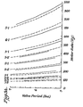
- FIGS. 3A and 3B There may be seen in FIGS. 3A and 3B a graphical representation of the resonance relationships-between the valve period and the pump or motor rate and for selected major harmonics between the valve period and the motor rate. These relationships are those at which the undesired interactions occur,between the pump rate and valve period for a particular pump.
- the dashed lines 60 bearing the desigations 1/2, 2/3, 3/4, 1/1, etc. represent the regions at which the valve period and the motor rate will interact to cause slowly varying concentrations.
- valve periods are selected which do not lie near these interaction or resonance lines. More specifically, blend concentration errors are avoided by deliberately setting the valve period as specified functions of the flow rate, i.e., the motor rate.
- These specified functions or nonresonant regions are denoted by straight line segments 62 (solid lines) drawn in the graph of FIGS. 3A and 3B.
- the straight line segments denote safe operating regions for the valve period as a function of motor rate for every motor rate that would typically be used in a particular pumping system. It is noted that as motor rates increase, different harmonics of the valve period and motor rate interact. It will be appreciated, of course, that the relationship illustrated in FIGS. 3A and 3B are for a specific pump, in this case the pump used in the Du Pont Model 850 HPLC unit. Formulas for determining these relationships are discussed below.
- Each line segment 62 representing a safe asynchronous operating region, is defined by the formula where VPS(I), MS(I), MRS(I) are constants-described in Table 1 below, depending on the motor rate segment I, and f p is the desired motor rate. These motor rate segments ranging from 80 Hz to 4050 Hz are shown tabulated in the following table.
- the base or starting point of these straight line segments is selected so that each line is mutually exclusive and does not overlap any other line.
- the solvent ratio control 38 stores this table and solves the formula using the stored constants for each selected pump rate (motor rate-MRS.) and controls the valve switching accordingly.
- the solvent ratio control 38 (FIG. 1) has a microprocessor which computes following the flow chart depicted in FIG. 4 in which the flow rate and desired fluid composition are inputs from the operator at the control panel 30.
- the pump drive control 34 calculates the motor rate needed to achieve such flow and controls the pump drive 40 accordingly for operating the pump heads 24, 26 and 28 at the desired rate.
- the valve period needed for asychronous or noninteractive operation in accordance with this invention is computed by the solvent ratio control 38. This is accomplished by looking-up the necessary constants of stored Table 1 for that desired flow rate fp to calculate the valve period T and from that the open time for each valve.
- the output valve data is then used during the operating cycle to control the valves 14 to provide the desired blend. At this point the program stops until a new input flow rate and desired blend is inputed into the controller 32 by the operator.
- the system of this invention utilizing the controller 32 operates in essentially the same manner as the method just described utilizing the controller with its microprocessor (not shown) which functions with the flow rate and desired blend as inputs to control the pump drive 34 and the solvent ratio control 38.
- controller 32 instead of using a table lookup, may actually compute the valve period from the basic formula.
- This basic formula may be derived from the following analysis.
Landscapes
- Chemical & Material Sciences (AREA)
- Physics & Mathematics (AREA)
- General Physics & Mathematics (AREA)
- Immunology (AREA)
- Engineering & Computer Science (AREA)
- Biochemistry (AREA)
- General Health & Medical Sciences (AREA)
- Life Sciences & Earth Sciences (AREA)
- Health & Medical Sciences (AREA)
- Pathology (AREA)
- Analytical Chemistry (AREA)
- Automation & Control Theory (AREA)
- Chemical Kinetics & Catalysis (AREA)
- Control Of Positive-Displacement Pumps (AREA)
- Medicines Containing Material From Animals Or Micro-Organisms (AREA)
- Treatment Of Liquids With Adsorbents In General (AREA)
- Feeding, Discharge, Calcimining, Fusing, And Gas-Generation Devices (AREA)
- Accessories For Mixers (AREA)
Priority Applications (1)
| Application Number | Priority Date | Filing Date | Title |
|---|---|---|---|
| AT83109810T ATE45815T1 (de) | 1982-09-30 | 1983-09-30 | Verfahren und vorrichtung zur genauen zufuehrung von fluidmischungen. |
Applications Claiming Priority (2)
| Application Number | Priority Date | Filing Date | Title |
|---|---|---|---|
| US06/430,837 US4427298A (en) | 1982-09-30 | 1982-09-30 | Method and system for accurately providing fluid blends |
| US430837 | 1982-09-30 |
Publications (3)
| Publication Number | Publication Date |
|---|---|
| EP0105496A2 true EP0105496A2 (de) | 1984-04-18 |
| EP0105496A3 EP0105496A3 (en) | 1985-07-10 |
| EP0105496B1 EP0105496B1 (de) | 1989-08-23 |
Family
ID=23709268
Family Applications (1)
| Application Number | Title | Priority Date | Filing Date |
|---|---|---|---|
| EP83109810A Expired EP0105496B1 (de) | 1982-09-30 | 1983-09-30 | Verfahren und Vorrichtung zur genauen Zuführung von Fluidmischungen |
Country Status (6)
| Country | Link |
|---|---|
| US (1) | US4427298A (de) |
| EP (1) | EP0105496B1 (de) |
| AT (1) | ATE45815T1 (de) |
| AU (1) | AU562105B2 (de) |
| CA (1) | CA1200699A (de) |
| DE (1) | DE3380451D1 (de) |
Cited By (2)
| Publication number | Priority date | Publication date | Assignee | Title |
|---|---|---|---|---|
| EP0461382A3 (en) * | 1990-05-04 | 1992-04-29 | Bio-Rad Laboratories, Inc. | Coordinated chromatography system |
| EP0467665A3 (en) * | 1990-07-18 | 1992-11-04 | Dorr-Oliver Incorporated | Gradient generation control for large scale liquid chromatography |
Families Citing this family (35)
| Publication number | Priority date | Publication date | Assignee | Title |
|---|---|---|---|---|
| DE3232401A1 (de) | 1982-08-31 | 1984-03-01 | Bayer Ag, 5090 Leverkusen | Strukturierter aufbau und dezentrale fuehrung von produktionsanlagen |
| US4614438A (en) * | 1984-04-24 | 1986-09-30 | Kabushiki Kaisha Kokusai Technicals | Method of mixing fuel oils |
| US4595496A (en) * | 1984-06-29 | 1986-06-17 | Millipore Corporation | Liquid composition control |
| DE3431112A1 (de) * | 1984-08-24 | 1986-03-06 | Spühl AG, St. Gallen | Mischkopf zur reaktiven mischung von kunststoff-komponenten |
| DE3442227A1 (de) * | 1984-11-19 | 1986-05-28 | Kernforschungsanlage Jülich GmbH, 5170 Jülich | Verfahren und vorrichtung zur ionenchromatographischen bestimmung des spurengehalts von waessrigen proben |
| US4794806A (en) * | 1987-02-13 | 1989-01-03 | Nicoli David F | Automatic dilution system |
| US4919595A (en) * | 1987-03-03 | 1990-04-24 | Beckman Instruments, Inc. | Fluid delivery system with deficit flow compensation |
| JPS63278539A (ja) * | 1987-05-11 | 1988-11-16 | Tosoh Corp | 液分注装置 |
| US4767279A (en) * | 1987-06-02 | 1988-08-30 | Millipore Corporation | Fluid composition and volumetric delivery control |
| CA1290744C (en) * | 1987-07-08 | 1991-10-15 | Laurent Verreault | Process and an apparatus for mixing substances |
| US5423607A (en) * | 1991-05-03 | 1995-06-13 | Dolco Packaging Corp. | Method for blending diverse blowing agents |
| US5823669A (en) * | 1991-05-03 | 1998-10-20 | Lolco Packaging Corp. | Method for blending diverse blowing agents |
| WO1996026002A1 (en) * | 1995-02-24 | 1996-08-29 | Exxon Chemical Patents Inc. | Additive blending system and method |
| US6056431A (en) * | 1997-09-05 | 2000-05-02 | Eastman Kodak Company | Modified passive liquefier batch transition process |
| EP1305107B1 (de) * | 2000-07-31 | 2006-09-20 | Kinetics Chempure Systems, Inc. | Verfahren und vorrichtung zum mischen von prozessmaterialien |
| DE10048513A1 (de) * | 2000-09-29 | 2002-04-11 | Degussa | Verfahren zur kontinuierlichen Herstellung von Stoff- und Reaktionsgemischen und Vorrichtung zu seiner Durchführung |
| US6568559B2 (en) * | 2000-11-24 | 2003-05-27 | Wanner Engineering, Inc. | Termite control system with multi-fluid proportion metering and batch signal metering |
| US20050098578A1 (en) * | 2002-09-13 | 2005-05-12 | Ford Motor Company | System for dispensing reactant mixtures |
| CA2466799C (en) * | 2004-05-07 | 2011-10-18 | Oden Corporation | An improved continuous liquid stream blender |
| US20070185619A1 (en) * | 2004-09-02 | 2007-08-09 | Fermier Adam M | Automated solution generator |
| US20060093515A1 (en) * | 2004-11-03 | 2006-05-04 | Fermier Adam M | Automated solution generator |
| WO2008143828A1 (en) * | 2007-05-14 | 2008-11-27 | Clyde Meriwether Smith | Systems and methods for supplying and/or dispensing fluid |
| US20090068034A1 (en) * | 2007-09-12 | 2009-03-12 | Pumptec, Inc. | Pumping system with precise ratio output |
| EP2523749B1 (de) | 2010-01-11 | 2022-04-13 | Waters Technologies Corporation | System und gerüst zur lösungsmittelmischung in flüssigchromatographiesystemen |
| US9791107B2 (en) * | 2011-07-27 | 2017-10-17 | Agilent Technologies, Inc. | Packet-wise proportioning followed by immediate longitudinal mixing |
| US9316216B1 (en) | 2012-03-28 | 2016-04-19 | Pumptec, Inc. | Proportioning pump, control systems and applicator apparatus |
| US20130294969A1 (en) * | 2012-05-02 | 2013-11-07 | Nellcor Puritan Bennett Llc | Wireless, Reusable, Rechargeable Medical Sensors and System for Recharging and Disinfecting the Same |
| DE102012010544B4 (de) * | 2012-05-29 | 2017-02-09 | J. Wagner Ag | Verfahren und Vorrichtung zum Mischen wenigstens zweier flüssiger Komponenten |
| ITMI20130660A1 (it) * | 2013-04-22 | 2014-10-23 | Emanuela Paci | Stazione di stoccaggio, prelievo e ricircolo di una sostanza fluida |
| US20170223921A1 (en) * | 2016-02-08 | 2017-08-10 | Delaware Capital Formation, Inc. | On-site chemical blending and dispensing system |
| US10760557B1 (en) | 2016-05-06 | 2020-09-01 | Pumptec, Inc. | High efficiency, high pressure pump suitable for remote installations and solar power sources |
| US10823160B1 (en) | 2017-01-12 | 2020-11-03 | Pumptec Inc. | Compact pump with reduced vibration and reduced thermal degradation |
| EP4517089A3 (de) | 2019-11-27 | 2025-05-28 | Waters Technologies Corporation | Gradientenproportionierungsventil |
| DE102020129050A1 (de) * | 2020-11-04 | 2022-05-05 | Bürkert Werke GmbH & Co. KG | Mischersystem für ein System zur Flüssigkeitschromatographie |
| US12304161B2 (en) * | 2021-02-16 | 2025-05-20 | Vestas Wind Systems A/S | Manufacture of a wind turbine component |
Family Cites Families (13)
| Publication number | Priority date | Publication date | Assignee | Title |
|---|---|---|---|---|
| US3398689A (en) | 1966-01-05 | 1968-08-27 | Instrumentation Specialties Co | Apparatus providing a constant-rate two-component flow stream |
| US3446057A (en) | 1966-10-14 | 1969-05-27 | Varian Associates | Method and apparatus for chromatography |
| US3608869A (en) | 1969-05-28 | 1971-09-28 | Texaco Inc | System for blending liquid ingredients |
| US3869067A (en) | 1972-06-26 | 1975-03-04 | Du Pont | Apparatus for gradient elution |
| US4018685A (en) | 1975-10-24 | 1977-04-19 | Union Oil Company Of California | Automatic liquid mixing device |
| JPS52133294A (en) * | 1976-05-01 | 1977-11-08 | Nippon Bunko Kogyo Kk | Pumping system and liquid transfer process for liquid chromatography |
| US4004884A (en) | 1976-07-02 | 1977-01-25 | Hoffmann-La Roche Inc. | Time division metering system |
| US4128476A (en) | 1977-06-14 | 1978-12-05 | Spectra-Physics, Inc. | Carrier composition control for liquid chromatographic systems |
| US4162689A (en) | 1977-07-14 | 1979-07-31 | Hoffmann-La Roche Inc. | Time division flow control |
| DE2808183A1 (de) | 1978-02-25 | 1979-09-06 | Hedrich Vakuumanlagen Wilhelm | Vorrichtungen fuer giessharzanlagen zum kontrollieren gleicher und/oder unterschiedlicher, auch synchronisierter ausstossmengen fliessfaehiger bis hochviskoser medien |
| DE2905160C2 (de) | 1979-02-10 | 1981-01-08 | Hewlett-Packard Gmbh, 7030 Boeblingen | Vorrichtung für die Erzeugung von Elutionsmittelgradienten in der Flüssigkeitschromatographie |
| JPS55122149A (en) | 1979-03-14 | 1980-09-19 | Japan Spectroscopic Co | Method and apparatus for supplying solvent in liquid chromatograph |
| US4341327A (en) | 1980-02-28 | 1982-07-27 | Vernon Zeitz | Digital proportional metering pumping system |
-
1982
- 1982-09-30 US US06/430,837 patent/US4427298A/en not_active Expired - Fee Related
-
1983
- 1983-09-29 CA CA000438039A patent/CA1200699A/en not_active Expired
- 1983-09-29 AU AU19727/83A patent/AU562105B2/en not_active Ceased
- 1983-09-30 AT AT83109810T patent/ATE45815T1/de not_active IP Right Cessation
- 1983-09-30 EP EP83109810A patent/EP0105496B1/de not_active Expired
- 1983-09-30 DE DE8383109810T patent/DE3380451D1/de not_active Expired
Cited By (3)
| Publication number | Priority date | Publication date | Assignee | Title |
|---|---|---|---|---|
| EP0461382A3 (en) * | 1990-05-04 | 1992-04-29 | Bio-Rad Laboratories, Inc. | Coordinated chromatography system |
| US5135658A (en) * | 1990-05-04 | 1992-08-04 | Bio-Rad Laboratories, Inc. | Method for reducing detector noise in a chromatography system |
| EP0467665A3 (en) * | 1990-07-18 | 1992-11-04 | Dorr-Oliver Incorporated | Gradient generation control for large scale liquid chromatography |
Also Published As
| Publication number | Publication date |
|---|---|
| AU1972783A (en) | 1984-04-05 |
| DE3380451D1 (en) | 1989-09-28 |
| CA1200699A (en) | 1986-02-18 |
| US4427298A (en) | 1984-01-24 |
| EP0105496B1 (de) | 1989-08-23 |
| EP0105496A3 (en) | 1985-07-10 |
| AU562105B2 (en) | 1987-05-28 |
| ATE45815T1 (de) | 1989-09-15 |
Similar Documents
| Publication | Publication Date | Title |
|---|---|---|
| US4427298A (en) | Method and system for accurately providing fluid blends | |
| US4595496A (en) | Liquid composition control | |
| US5423661A (en) | Fluid metering, mixing and composition control system | |
| EP0327609B1 (de) | Gemisch- und volumensteuerung zur flüssigkeitslieferung | |
| EP0260764B1 (de) | Flüssigkeitschromatograph | |
| US11635065B2 (en) | Synchronization of supply flow paths | |
| US4233156A (en) | Liquid chromatography apparatus | |
| US5089124A (en) | Gradient generation control for large scale liquid chromatography | |
| US4433701A (en) | Polymer flood mixing apparatus and method | |
| US4128476A (en) | Carrier composition control for liquid chromatographic systems | |
| US20150008862A1 (en) | Intake profile for optimized utilization of motor characteristics | |
| US4964985A (en) | Liquid chromatograph | |
| US4162689A (en) | Time division flow control | |
| GB2332378A (en) | Liquid chromatography valved pumping system with flow dampers | |
| US4821761A (en) | Closed loop pump control system | |
| DE10029080B4 (de) | Verfahren und Vorrichtung zur Geschwindigkeitsmodulation für einen pulsationsfreien Betrieb einer Pumpe | |
| US3276460A (en) | Method and apparatus for monitoring and controlling the ratio of vapor volume to liquid volume of a fluid | |
| GB2389629A (en) | Improved accuracy of constituent proportions for a mixing pump | |
| SU1282823A3 (ru) | Способ регулировани соотношени компонентов смеси | |
| US4352374A (en) | Apparatus for diluting a concentrated solution | |
| JPS6082129A (ja) | 流体ブレンドを生成する方法および系 | |
| US5291418A (en) | Adjustment of electric potential by automatic titration | |
| JP2884727B2 (ja) | 濃度勾配及び/又は流量勾配作製装置 | |
| RU2023282C1 (ru) | Устройство для регулирования соотношения расходов растворов компонентов | |
| SU1657965A1 (ru) | Устройство дл дозировани многокомпонентных жидких смесей |
Legal Events
| Date | Code | Title | Description |
|---|---|---|---|
| PUAI | Public reference made under article 153(3) epc to a published international application that has entered the european phase |
Free format text: ORIGINAL CODE: 0009012 |
|
| AK | Designated contracting states |
Designated state(s): AT BE CH DE FR GB IT LI LU NL SE |
|
| PUAL | Search report despatched |
Free format text: ORIGINAL CODE: 0009013 |
|
| AK | Designated contracting states |
Designated state(s): AT BE CH DE FR GB IT LI LU NL SE |
|
| 17P | Request for examination filed |
Effective date: 19851217 |
|
| 17Q | First examination report despatched |
Effective date: 19870513 |
|
| RAP1 | Party data changed (applicant data changed or rights of an application transferred) |
Owner name: THE ANSPEC COMPANY, INC. |
|
| GRAA | (expected) grant |
Free format text: ORIGINAL CODE: 0009210 |
|
| AK | Designated contracting states |
Kind code of ref document: B1 Designated state(s): AT BE CH DE FR GB IT LI LU NL SE |
|
| REF | Corresponds to: |
Ref document number: 45815 Country of ref document: AT Date of ref document: 19890915 Kind code of ref document: T |
|
| PGFP | Annual fee paid to national office [announced via postgrant information from national office to epo] |
Ref country code: SE Payment date: 19890828 Year of fee payment: 7 |
|
| PGFP | Annual fee paid to national office [announced via postgrant information from national office to epo] |
Ref country code: LU Payment date: 19890927 Year of fee payment: 7 Ref country code: FR Payment date: 19890927 Year of fee payment: 7 |
|
| PGFP | Annual fee paid to national office [announced via postgrant information from national office to epo] |
Ref country code: DE Payment date: 19890928 Year of fee payment: 7 |
|
| REF | Corresponds to: |
Ref document number: 3380451 Country of ref document: DE Date of ref document: 19890928 |
|
| ET | Fr: translation filed | ||
| ITTA | It: last paid annual fee | ||
| PG25 | Lapsed in a contracting state [announced via postgrant information from national office to epo] |
Ref country code: LU Free format text: LAPSE BECAUSE OF NON-PAYMENT OF DUE FEES Effective date: 19890930 |
|
| PGFP | Annual fee paid to national office [announced via postgrant information from national office to epo] |
Ref country code: NL Payment date: 19890930 Year of fee payment: 7 Ref country code: GB Payment date: 19890930 Year of fee payment: 7 Ref country code: AT Payment date: 19890930 Year of fee payment: 7 |
|
| PGFP | Annual fee paid to national office [announced via postgrant information from national office to epo] |
Ref country code: CH Payment date: 19891004 Year of fee payment: 7 |
|
| PGFP | Annual fee paid to national office [announced via postgrant information from national office to epo] |
Ref country code: BE Payment date: 19891018 Year of fee payment: 7 |
|
| ITF | It: translation for a ep patent filed | ||
| PLBE | No opposition filed within time limit |
Free format text: ORIGINAL CODE: 0009261 |
|
| STAA | Information on the status of an ep patent application or granted ep patent |
Free format text: STATUS: NO OPPOSITION FILED WITHIN TIME LIMIT |
|
| 26N | No opposition filed | ||
| PG25 | Lapsed in a contracting state [announced via postgrant information from national office to epo] |
Ref country code: LI Effective date: 19900930 Ref country code: GB Effective date: 19900930 Ref country code: CH Effective date: 19900930 Ref country code: BE Effective date: 19900930 Ref country code: AT Effective date: 19900930 |
|
| PG25 | Lapsed in a contracting state [announced via postgrant information from national office to epo] |
Ref country code: SE Effective date: 19901001 |
|
| BERE | Be: lapsed |
Owner name: THE ANSPEC CY INC. Effective date: 19900930 |
|
| PG25 | Lapsed in a contracting state [announced via postgrant information from national office to epo] |
Ref country code: NL Effective date: 19910401 |
|
| NLV4 | Nl: lapsed or anulled due to non-payment of the annual fee | ||
| GBPC | Gb: european patent ceased through non-payment of renewal fee | ||
| PG25 | Lapsed in a contracting state [announced via postgrant information from national office to epo] |
Ref country code: FR Effective date: 19910530 |
|
| REG | Reference to a national code |
Ref country code: CH Ref legal event code: PL |
|
| PG25 | Lapsed in a contracting state [announced via postgrant information from national office to epo] |
Ref country code: DE Effective date: 19910601 |
|
| REG | Reference to a national code |
Ref country code: FR Ref legal event code: ST |
|
| EUG | Se: european patent has lapsed |
Ref document number: 83109810.8 Effective date: 19910603 |