EP0105516A1 - Schalteranordnung - Google Patents
Schalteranordnung Download PDFInfo
- Publication number
- EP0105516A1 EP0105516A1 EP83109869A EP83109869A EP0105516A1 EP 0105516 A1 EP0105516 A1 EP 0105516A1 EP 83109869 A EP83109869 A EP 83109869A EP 83109869 A EP83109869 A EP 83109869A EP 0105516 A1 EP0105516 A1 EP 0105516A1
- Authority
- EP
- European Patent Office
- Prior art keywords
- switch
- magnet
- protective tube
- housing
- tube contact
- Prior art date
- Legal status (The legal status is an assumption and is not a legal conclusion. Google has not performed a legal analysis and makes no representation as to the accuracy of the status listed.)
- Granted
Links
Images
Classifications
-
- H—ELECTRICITY
- H01—ELECTRIC ELEMENTS
- H01H—ELECTRIC SWITCHES; RELAYS; SELECTORS; EMERGENCY PROTECTIVE DEVICES
- H01H36/00—Switches actuated by change of magnetic field or of electric field, e.g. by change of relative position of magnet and switch, by shielding
- H01H36/0006—Permanent magnet actuating reed switches
- H01H36/0046—Limit switches, also fail-safe operation or anti-tamper considerations
Definitions
- the invention relates to a switch arrangement comprising a switch base part with a switch housing and a protective tube contact arranged therein and a switching magnet which is movable relative to the base part and is assigned to the protective tube contact.
- a switch arrangement In the case of device housings for electrical devices, for example a device housing of a high-speed printer, a switch arrangement is often provided which interrupts the power supply for the electrical device for safety reasons when the housing cover is opened.
- the switch arrangements previously used for this purpose work mechanically by pressing a switch button of the switch arrangement when the housing cover is closed.
- close tolerances between the cover and the lower part of the housing are required.
- the shocks and vibrations that occur during operation of the device in particular, for example in the case of a high-speed printer, may lead to wear and ultimately to failure of the switch due to the narrow tolerances. For this reason, these switches are often simply put out of function.
- switch arrangements of the type mentioned at the outset are known in which the actual switching element, namely the protective tube contact (reed element), can be actuated by a magnet which is arranged so as to be movable relative to it.
- This switch arrangement also works reliably with larger tolerances and its function is completely insensitive to mechanical shocks and vibrations.
- the previously known switch arrangements of this type would have the disadvantage in the use of a device housing described above that after opening the cover, the protective tube contact cannot be actuated, for example by commission the device for service purposes with the housing open.
- the second magnet is preferably arranged in the switch housing, in which case an opening is expediently provided in the switch housing through which the rocker can be moved from its waiting position into the switching position by means of a tool. This ensures that the second magnet cannot be moved into its switching position unintentionally or easily, but only with the aid of a tool, for example a screwdriver.
- An adjustability of the second magnet can be achieved in a very simple manner in that it is arranged on a rocker arm which is pivotably mounted in the switch housing.
- the rocker is preferably between a horizontal position corresponding to the switching position of the second magnet and one 3er waiting position of the second magnet corresponding vertical position pivotable.
- the first and the second magnet are expediently arranged in such a way that in their respective switching position they lie on opposite sides of the protective tube contact. If the protective tube contact should be located on a circuit board arranged in the switch housing, an opening for the passage of the second magnet is expediently provided in the circuit board, so that the second magnet in its switching position can be brought sufficiently close to the protective tube contact.
- This design in conjunction with the arrangement of the magnet on a rocker arm, enables the second magnet to be transferred back to its waiting position in a simple manner, in that the first and second magnets are designed as permanent magnets and are arranged in such a way that their switch positions have the same name Magnetic poles face each other.
- the second magnet is pushed away from the protective tube contact when the first switching magnet is brought up, for example when the housing cover is closed, so that the rocker with the second magnet falls back into its waiting position, while in the switching position due to the magnetic interaction between the protective tube contact and the second one Magnet is held.
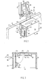
- FIG. 1 shows a section 10 of a housing wall of a housing (not shown) for an electrical device, for example a printer, and a section 12 of an associated housing cover, on the edge of which the housing wall 10 faces a shock absorber strip 14 made of an elastic material is arranged.
- a switch arrangement generally designated 16, is provided, which interrupts the power supply to the electrical device when the housing cover 12 is opened.
- the switch arrangement 16 comprises a switch base part 18 with a switch housing 20 consisting of an insulating material, which is fastened to the device housing or to the device itself in a manner not shown by means of spring tongues 24 formed on its end faces 22.
- the switch housing 20 receives a circuit board 26 which carries a reed element or a protective tube contact 28.
- the circuit board 26 can be snapped into two elastically deflectable latching hooks 30, which epatiusedeck Properties from the inside of G 32 project downward.
- the circuit board 26 carries a circuit arrangement, not shown, which is known per se, for controlling the power supply of the device.
- a permanent magnet 34 which is attached to a profile bracket 36, is used to actuate the reed element 28. which in turn is fastened with the aid of screws 38 to the inside of the housing cover 12 in such a way that when the cover 12 is closed it is brought sufficiently close to the cover surface 32 of the switch housing 20 in order to actuate the reed contact 28.
- a rocker 40 is pivotally mounted about an axis parallel to the end wall 22.
- the rocker 40 has two pins 42 which can be latched into grooves 46 formed on the inside of the side walls 44 of the switch housing 20, so that the rocker 40 can be freely pivoted between the vertical position shown in the figures and a horizontal position.
- the rocker 40 carries a further permanent magnet 48 which can be pivoted to the underside of the reed element 28 with the help of the rocker 40.
- the printed circuit board 26 has an opening through which the permanent magnet 48 can pass. The permanent magnet 48 serves to actuate the reed element 28 when the cover 12 is open.
- the device can also be put into operation with the cover open, for example for service work.
- an opening 50 is provided in the end wall 22 of the switch housing 20, which opening is dimensioned such that only a thin tool can be pushed through, such as, for example the tip of a screwdriver 52, which is indicated in FIG. 2.
- the rocker 40 is pivoted until the permanent magnet 48 assumes its switching position.
- the permanent magnet 48 is arranged relative to the switching magnet 34 such that the poles of the same name of both magnets face each other when they assume their respective switching positions. As a result, the permanent magnet 48 is repelled by the permanent magnet 34 when the lid is closed, so that the rocker 40 returns to its vertical position. The original state is thus automatically restored by the reed element 28 being actuated solely by the permanent magnet 34.
- the switch arrangement described above is extremely reliable and unaffected by mechanical vibrations or shocks. At the same time, it is ensured that after opening the device housing, the power supply to the device cannot be switched on unintentionally or without the aid of a tool.
- the rocker 40 cannot be adjusted through the opening 50, for example with the aid of a finger.
- the switch arrangement described above can of course be used for a wide variety of purposes. The use described above in a housing for electrical devices represents only one application, without the scope of protection being restricted to this application.
Landscapes
- Switches That Are Operated By Magnetic Or Electric Fields (AREA)
- Switch Cases, Indication, And Locking (AREA)
Abstract
Description
- Die Erfindung betrifft eine Schalteranordnung, umfassend ein Schalterbasisteil mit einem Schaltergehäuse und einem darin angeordneten Schutzrohrkontakt und einen gegenüber dem Basisteil beweglichen, dem Schutzrohrkontakt zugeordneten Schaltmagneten.
- Bei Gerätegehäusen für elektrische Geräte, beispielsweise einem Gerätegehäuse eines Schnelldruckers, ist häufig eine Schalteranordnung vorgesehen, welche beim öffnen des Gehäusedeckels die Stromversorgung für das elektrische Gerät aus Sicherheitsgründen unterbricht. Üblicherweise arbeiten die bisher für diesen Zweck verwendeten Schalteranordnungen mechanisch, indem beim Schließen des Gehäusedeckels ein Schaltknopf der Schalteranordnung gedrückt wird. Um ein einwandfreies Schalten in diesem Falle zu erreichen, sind enge Toleranzen zwischen Deckel und Gehäuseunterteil erforderlich. Die beim Betrieb des Gerätes, insbesondere etwa bei einem Schnelldrucker auftretenden Erschütterungen und Schwingungen führen aufgrund der engen Toleranzen unter Umständen zu einem Verschleiß und letztlich zum Ausfall des Schalters. Aus diesem Grunde werden diese Schalter unzulässigerweise häufig einfach außer Funktion gesetzt.
- Grundsätzlich sind Schalteranordnungen der eingangs genannten Art bekannt, bei denen das eigentliche Schaltelement, nämlich der Schutzrohrkontakt (Reed-Element) durch einen ihm gegenüber beweglich angeordneten Magneten betätigt werden kann. Diese Schalteranordnung funktioniert auch zuverlässig bei größeren Toleranzen und ist in ihrer -Funktion völlig unempfindlich gegen mechanische Erschütterungen und Schwingungen. Die-bisher bekannten Schalteranordnungen dieser Art hätten jedoch bei der oben beschriebenen Verwendung an einem Gerätegehäuse den Nachteil, daß sich nach dem Öffnen des Deckels der Schutzrohrkontakt nicht betätigen läßt, um beispielsweise das Gerät für Servicezwecke bei geöffnetem Gehäuse in Betrieb zu nehmen.
- Der Erfindung liegt die Aufgabe zugrunde, eine Schalteranordnung der eingangs genannten Art anzugeben, bei welcher der Schutzrohrkontakt auch unabhängig von dem Schaltmagneten betätigbar ist:
- Diese Aufgabe wird erfindungsgemäß dadurch gelöst, daß dem Schutzrohrkontakt ein weiterer Magnet zugeordnet ist, der an dem Schaltergehäuse angeordnet und zwischen einer dem Schutzrohrkontakt nahen Schaltstellung und einer dem Schutzrohrkontakt fernen Wartestellung verstellbar ist. Bezogen auf den oben diskutierten Anwendungsfall kann somit der Schutzrohrkontakt auch dann geschlossen werden, wenn der beispielsweise an dem Gehäusedeckel befestigte Schaltmagnet durch das Öffnen des Deckels den Schutzrohrkontakt nicht mehr betätigen kann.
- Vorzugsweise ist der zweite Magnet in dem Schaltergehäuse angeordnet, wobei in diesem Falle in dem Schaltergehäuse zweckmäßigerweise eine öffnung vorgesehen ist, durch die hindurch die Schwinge mittels eines Werkzeuges aus ihrer Wartestellung in die Schaltstellung überführbar ist. Dadurch wird sichergestellt, daß der zweite Magnet nicht unabsichtlich oder ohne weiteres, sondern nur mit Hilfe eines Werkzeuges, beispielsweise eines Schraubenziehers, in seine Schaltstellung überführt werden kann.
- Eine Verstellbarkeit des zweiten Magneten läßt sich auf sehr einfache Art dadurch erreichen, daß er an einer Schwinge angeordnet ist, die in dem Schaltergehäuse schwenkbar gelagert ist. Vorzugsweise ist dabei die Schwinge zwischen einer der Schaltstellung des zweiten Magneten entsprechenden horizontalen Stellung und einer 3er Wartestellung des zweiten Magneten entsprechenden vertikalen Stellung verschwenkbar.
- Zweckmäßigerweise sind der erste und der zweite Magnet derart angeordnet, daß sie in ihrer jeweiligen Schaltstellung auf einander entgegengesetzten Seiten des Schutzrohrkontaktes liegen. Wenn sich der Schutzrohrkontakt auf einer in dem Schaltergehäuse angeordneten Schaltungsplatine befinden sollte, ist in der Schaltungsplatine zweckmäßigerweise eine öffnung zum Durchtritt des zweiten Magneten vorgesehen, so daß der zweite Magnet in seiner Schaltstellung ausreichend nah an den Schutzrohrkontakt herangeführt werden kann. Diese Ausbildung gibt in Verbindung mit der Anordnung des Magneten an einer Schwinge die Möglichkeit, den zweiten Magneten auf einfache Weise wieder in seine Wartestellung zu überführen, indem der erste und der zweite Magnet als Dauermagnete ausgebildet und derart angeordnet sind, daß in ihren Schaltstellungen die gleichnamigen Magnetpole einander zugewandt sind. Dadurch wird der zweite Magnet beim Heranführen des ersten Schaltmagneten, also beispielsweise beim Schließen des Gehäusedeckels, vom Schutzrohrkontakt weggestoßen, so daß die Schwinge mit dem zweiten Magneten in ihre Wartestellung zurückfällt, während sie in der Schaltstellung durch die magnetische Wechselwirkung zwischen dem Schutzrohrkontakt und dem zweiten Magneten gehalten wird.
- Weitere Merkmale und Vorteile der Erfindung ergeben sichaus der folgenden Beschreibung, welche in Verbindung mit den beigefügten Zeichnungen die Erfindung anhand eines Ausführungsbeispieles erläutert. Es zeigen:
- Fig. 1 eine perspektivische halbschematische Darstellung der an einem Gerätegehäuse angeordneten erfindungsgemäßen Schalteranordnung und
- Fig. 2 einen Schnitt durch das Schalterbasisteil entlang der Linie II-II in Fig. 1.
- In Fig. 1 erkennt man einen mit 10 bezeichneten Abschnitt einer Gehäusewand eines im übrigen nicht dargestellten Gehäuses für ein elektrisches Gerät, beispielsweise einen Drucker, und einen Abschnitt 12 eines dazugehörigen Gehäusedeckels, an dessen der Gehäusewand 10 zugekehrter Kante eine Stoßdämpferleiste 14 aus einem elastischen Material angeordnet ist. Aus Sicherheitsgründen ist eine allgemein mit 16 bezeichnete Schalteranordnung vorgesehen;die beim öffnen des Gehäusedeckels 12 die Stromzufuhr zu dem elektrischen Gerät unterbricht. Die Schalteranordnung 16 umfaßt ein Schalterbasisteil 18 mit einem aus einem Isoliermaterial bestehenden Schaltergehäuse 20, das mit Hilfe von an seinen Stirnflächen 22 ausgebildeten Federzungen 24 in nicht dargestellter Weise an dem Gerätegehäuse oder an dem Gerät selber befestigt ist.
- Das Schaltergehäuse 20 nimmt eine Leiterplatte 26 auf, die ein Reed-Element oder einen Schutzrohrkontakt 28 trägt. Die Leiterplatte 26 ist in zwei elastisch auslenkbare Rasthaken 30 einschnappbar, die von der Innenseite der Gehäusedeckfläche 32 nach unten ragen. Die Leiterplatte 26 trägt eine nicht dargestellte und an sich bekannte Schaltungsanordnung zur Steuerung der Stromzufuhr des Gerätes.
- Zur Betätigung des Reed-Elementes 28 dient ein Permanentmagnet 34, der an einem Profilwinkel 36 befestigt ist, der seinerseits mit Hilfe von Schrauben 38 an der Innenseite des Gehäusedeckels 12 derart befestigt ist, daß er beim Schließen des Deckels 12 hinreichend nahe an die Deckfläche 32 des Schaltergehäuses 20 gebracht wird, um den Reed-Kontakt 28 zu betätigen.
- In dem Schaltergehäuse 20 ist nahe der einen Stirnwand 22 eine Schwinge 40 um eine zur Stirnwand 22 parallele Achse schwenkbar gelagert. Die Schwinge 40 weist zu diesem Zweck zwei Zapfen 42 auf, die in an der Innenseite der Seitenwände 44 des Schaltergehäuses 20 ausgebildete Nuten 46 einrastbar sind, so daß die Schwinge 40 frei zwischen der in den Figuren dargestellten vertikalen Stellung und einer horizontalen Stellung verschwenkbar ist. Die Schwinge 40 trägt einen weiteren Permanentmagneten 48, der mit Hilfe der Schwinge 40 an die Unterseite des Reed-Elementes 28 geschwenkt werden kann. Die Leiterplatte 26 weist zu diesem Zwecke eine Öffnung auf, durch die der Permanentmagnet 48 hindurchtreten kann. Der Permanentmagnet 48 dient dazu, das Reed-Element 28 zu betätigen, wenn der Deckel 12 geöffnet ist. Auf diese Weise kann das Gerät auch bei geöffnetem Deckel, beispielsweise für Service-Arbeiten, in Betrieb genommen werden. Um die Schwinge 40 in ihre horizontale Stellung zu verschwenken und damit den Permanentmagneten 48 in seine Schaltstellung zu überführen, ist in der Stirnwand 22 des Schaltergehäuses 20 eine Öffnung 50 vorgesehen, die so bemessen ist, daß nur ein dünnes Werkzeug hindurchgeschoben werden kann, wie beispielsweise die Spitze eines Schraubendrehers 52, die in der Fig. 2 angedeutet ist. Mit Hilfe dieses Schraubendrehers wird die Schwinge 40 so weit verschwenkt, bis der Permanentmagnet 48 seine Schaltstellung einnimmt.
- Der Permanentmagnet 48 ist relativ zum Schaltmagneten 34 derart angeordnet, daß die gleichnamigen Pole beider Magnete einander zugekehrt sind, wenn sie ihre jeweilige Schaltstellung einnehmen. Dadurch wird beim Schließen des Deckels der Permanentmagnet 48 vom Permanentmagnet 34 abgestoßen, so daß die Schwinge 40 in ihre vertikale Stellung zurückkehrt. Damit wird automatisch wieder der Ursprungszustand hergestellt, indem das Reed-Element 28 allein durch den Permanentmagneten 34 betätigt wird.
- Die vorstehend beschriebene Schalteranordnung ist außerordentlich funktionssicher und unanfällig gegen mechanische Schwingungen oder Erschütterungen. Gleichzeitig ist sichergestellt, daß nach dem öffnen des Gerätegehäuses die Stromzufuhr zum Gerät nicht unbeabsichtigt oder ohne Zuhilfenahme eines Werkzeuges wieder eingeschaltet werden kann. Die Schwinge 40 kann durch die öffnung 50 nicht beispielsweise mit Hilfe eines Fingers verstellt werden. Die vorstehend beschriebene Schalteranordnung kann selbstverständlich für die verschiedensten Zwecke verwendet werden. Die vorstehend beschriebene Verwendung in einem Gehäuse für elektrische Geräte stellt nur einen Anwendungsfall dar, ohne daß der Schutzumfang auf diesen Anwendungsfall beschränkt sein soll.
Claims (8)
Applications Claiming Priority (2)
| Application Number | Priority Date | Filing Date | Title |
|---|---|---|---|
| DE3236659 | 1982-10-04 | ||
| DE3236659A DE3236659C2 (de) | 1982-10-04 | 1982-10-04 | Schalteranordnung |
Publications (2)
| Publication Number | Publication Date |
|---|---|
| EP0105516A1 true EP0105516A1 (de) | 1984-04-18 |
| EP0105516B1 EP0105516B1 (de) | 1986-02-12 |
Family
ID=6174872
Family Applications (1)
| Application Number | Title | Priority Date | Filing Date |
|---|---|---|---|
| EP83109869A Expired EP0105516B1 (de) | 1982-10-04 | 1983-10-03 | Schalteranordnung |
Country Status (2)
| Country | Link |
|---|---|
| EP (1) | EP0105516B1 (de) |
| DE (2) | DE3236659C2 (de) |
Families Citing this family (1)
| Publication number | Priority date | Publication date | Assignee | Title |
|---|---|---|---|---|
| DE19547199A1 (de) * | 1995-12-18 | 1997-06-19 | Valeo Deutschland Gmbh & Co | Schalter für ein Kraftfahrzeug |
Citations (3)
| Publication number | Priority date | Publication date | Assignee | Title |
|---|---|---|---|---|
| DE1590157B2 (de) * | 1966-09-29 | 1973-03-29 | Robert Bosch Gmbh, 7000 Stuttgart | Magnetisch gesteuerte schaltvorrichtung |
| CH565445A5 (en) * | 1974-03-26 | 1975-08-15 | Passoni Gianfranco | Hermetically-sealed bistable reed-switch - has internal and external north poles operating contacts throu sealed housing |
| DE2349470B2 (de) * | 1973-10-02 | 1976-08-12 | Siemens AG, 1000 Berlin und 8000 München | Elektrisch betreibbares geraet mit einem sicherheitsschalter |
Family Cites Families (6)
| Publication number | Priority date | Publication date | Assignee | Title |
|---|---|---|---|---|
| CH417730A (de) * | 1964-07-06 | 1966-07-31 | Hasler Ag | Schalter mit Permanentmagnet und Schutzrohrkontakt |
| DE2033682A1 (de) * | 1970-07-07 | 1972-01-27 | Budapesti Radiotechnikai Gyar | Anschlußvornchtung fur elektrische Gerate |
| DE2335582A1 (de) * | 1973-07-13 | 1974-11-14 | Walther Bueromasch Gmbh | Kontaktunterbrechungseinrichtung durch den haubendeckel fuer bueromaschinen |
| US4213110A (en) * | 1978-07-20 | 1980-07-15 | Holce Thomas J | Proximity switch having adjustable sensitivity |
| DE2909448A1 (de) * | 1979-03-10 | 1980-09-18 | Wolfgang Zach | Magnetisch betaetigter elektrischer schalter |
| DE2944465C2 (de) * | 1979-11-03 | 1982-03-04 | Triumph-Adler Aktiengesellschaft für Büro- und Informationstechnik, 8500 Nürnberg | Schaltvorrichtung zum Unterbrechen des Stromkreises für elektrisch angetriebene Schreib- u.ä. Büromaschinen |
-
1982
- 1982-10-04 DE DE3236659A patent/DE3236659C2/de not_active Expired
-
1983
- 1983-10-03 DE DE8383109869T patent/DE3362127D1/de not_active Expired
- 1983-10-03 EP EP83109869A patent/EP0105516B1/de not_active Expired
Patent Citations (3)
| Publication number | Priority date | Publication date | Assignee | Title |
|---|---|---|---|---|
| DE1590157B2 (de) * | 1966-09-29 | 1973-03-29 | Robert Bosch Gmbh, 7000 Stuttgart | Magnetisch gesteuerte schaltvorrichtung |
| DE2349470B2 (de) * | 1973-10-02 | 1976-08-12 | Siemens AG, 1000 Berlin und 8000 München | Elektrisch betreibbares geraet mit einem sicherheitsschalter |
| CH565445A5 (en) * | 1974-03-26 | 1975-08-15 | Passoni Gianfranco | Hermetically-sealed bistable reed-switch - has internal and external north poles operating contacts throu sealed housing |
Also Published As
| Publication number | Publication date |
|---|---|
| DE3236659C2 (de) | 1986-06-19 |
| DE3236659A1 (de) | 1984-04-05 |
| EP0105516B1 (de) | 1986-02-12 |
| DE3362127D1 (en) | 1986-03-27 |
Similar Documents
| Publication | Publication Date | Title |
|---|---|---|
| DE69119073T2 (de) | Solenoid betätigte schaltvorrichtung | |
| DE4413043C2 (de) | Kupplungsvorrichtung | |
| EP0198099B1 (de) | Schütz, insbesondere Hilfs- oder Motorschütz | |
| EP0033841B1 (de) | Relais | |
| EP0602305A1 (de) | An einer Tragschiene befestigbares Installationsgerät | |
| DE9001448U1 (de) | Schaltvorrichtung mit geschützten Unterbrechern | |
| DE4129938A1 (de) | Druckknopfschalter | |
| EP0222181A1 (de) | Überstromschutzschalter | |
| EP0028000A1 (de) | Drucktaste | |
| DE3545149C2 (de) | ||
| DE1175902B (de) | Elektromagnetischer Mehrfachtonabnehmer | |
| EP1264325B1 (de) | Elektromagnetisches schaltgerät, insbesondere schütz | |
| EP0241412B1 (de) | Anordnung zur Montage von Hilfsauslösern | |
| DE2902885C2 (de) | Kontaktfederanordnung für elektromagnetische Drehankerrelais | |
| EP0105516B1 (de) | Schalteranordnung | |
| DE3219294C2 (de) | ||
| CH690345A5 (de) | Abgedichteter elektrischer Schalter und Schalteranordnung. | |
| DE3242821C2 (de) | Staubdichter Blattfederkontakt-Schalter | |
| DE112017007241B4 (de) | Auslöseschalter | |
| DE1248137B (de) | Kontaktanordnung in einem elektrischen Schalter | |
| AT390706B (de) | Vorrichtung zum einschieben bzw. ausziehen von mit steckerleisten versehenen karten oder anderen einschueben | |
| EP0130511B1 (de) | Elektromagnetisches Relais mit Umschaltfeder | |
| DE3411597A1 (de) | Schiebeschalter | |
| DE4134799C2 (de) | Betätigungsvorrichtung für einen Schalter mit einem Bowdenzug | |
| DE3423854C2 (de) |
Legal Events
| Date | Code | Title | Description |
|---|---|---|---|
| PUAI | Public reference made under article 153(3) epc to a published international application that has entered the european phase |
Free format text: ORIGINAL CODE: 0009012 |
|
| 17P | Request for examination filed |
Effective date: 19840120 |
|
| AK | Designated contracting states |
Designated state(s): DE FR GB IT NL SE |
|
| RBV | Designated contracting states (corrected) |
Designated state(s): DE FR GB IT NL SE |
|
| GRAA | (expected) grant |
Free format text: ORIGINAL CODE: 0009210 |
|
| AK | Designated contracting states |
Designated state(s): DE FR GB IT NL SE |
|
| REF | Corresponds to: |
Ref document number: 3362127 Country of ref document: DE Date of ref document: 19860327 |
|
| ITF | It: translation for a ep patent filed | ||
| ET | Fr: translation filed | ||
| PLBE | No opposition filed within time limit |
Free format text: ORIGINAL CODE: 0009261 |
|
| STAA | Information on the status of an ep patent application or granted ep patent |
Free format text: STATUS: NO OPPOSITION FILED WITHIN TIME LIMIT |
|
| 26N | No opposition filed | ||
| ITPR | It: changes in ownership of a european patent |
Owner name: CAMBIO RAGIONE SOCIALE;SIEMENS NIXDORF INFORMATION |
|
| NLT1 | Nl: modifications of names registered in virtue of documents presented to the patent office pursuant to art. 16 a, paragraph 1 |
Owner name: SIEMENS NIXDORF INFORMATIONSSYSTEME AKTIENGESELLSC |
|
| PGFP | Annual fee paid to national office [announced via postgrant information from national office to epo] |
Ref country code: FR Payment date: 19910816 Year of fee payment: 9 |
|
| PGFP | Annual fee paid to national office [announced via postgrant information from national office to epo] |
Ref country code: SE Payment date: 19910902 Year of fee payment: 9 |
|
| PGFP | Annual fee paid to national office [announced via postgrant information from national office to epo] |
Ref country code: DE Payment date: 19911016 Year of fee payment: 9 |
|
| ITTA | It: last paid annual fee | ||
| PGFP | Annual fee paid to national office [announced via postgrant information from national office to epo] |
Ref country code: NL Payment date: 19911031 Year of fee payment: 9 |
|
| REG | Reference to a national code |
Ref country code: FR Ref legal event code: CD |
|
| PGFP | Annual fee paid to national office [announced via postgrant information from national office to epo] |
Ref country code: GB Payment date: 19920914 Year of fee payment: 10 |
|
| PG25 | Lapsed in a contracting state [announced via postgrant information from national office to epo] |
Ref country code: SE Effective date: 19921004 |
|
| PG25 | Lapsed in a contracting state [announced via postgrant information from national office to epo] |
Ref country code: NL Effective date: 19930501 |
|
| NLV4 | Nl: lapsed or anulled due to non-payment of the annual fee | ||
| PG25 | Lapsed in a contracting state [announced via postgrant information from national office to epo] |
Ref country code: FR Effective date: 19930630 |
|
| PG25 | Lapsed in a contracting state [announced via postgrant information from national office to epo] |
Ref country code: DE Effective date: 19930701 |
|
| REG | Reference to a national code |
Ref country code: FR Ref legal event code: ST |
|
| PG25 | Lapsed in a contracting state [announced via postgrant information from national office to epo] |
Ref country code: GB Effective date: 19931003 |
|
| GBPC | Gb: european patent ceased through non-payment of renewal fee |
Effective date: 19931003 |
|
| EUG | Se: european patent has lapsed |
Ref document number: 83109869.4 Effective date: 19930510 |