EP0105574B1 - Mélangeur magnétique flottant pour milieu de culture - Google Patents
Mélangeur magnétique flottant pour milieu de culture Download PDFInfo
- Publication number
- EP0105574B1 EP0105574B1 EP83303260A EP83303260A EP0105574B1 EP 0105574 B1 EP0105574 B1 EP 0105574B1 EP 83303260 A EP83303260 A EP 83303260A EP 83303260 A EP83303260 A EP 83303260A EP 0105574 B1 EP0105574 B1 EP 0105574B1
- Authority
- EP
- European Patent Office
- Prior art keywords
- flask
- stirrer
- liquid
- liquid medium
- magnet
- Prior art date
- Legal status (The legal status is an assumption and is not a legal conclusion. Google has not performed a legal analysis and makes no representation as to the accuracy of the status listed.)
- Expired
Links
- 238000007667 floating Methods 0.000 title description 9
- 239000001963 growth medium Substances 0.000 title description 5
- 239000007788 liquid Substances 0.000 claims description 54
- 239000002609 medium Substances 0.000 claims description 23
- 238000000034 method Methods 0.000 claims description 22
- 238000003756 stirring Methods 0.000 claims description 13
- 239000000463 material Substances 0.000 claims description 10
- 239000006143 cell culture medium Substances 0.000 claims description 5
- 239000004033 plastic Substances 0.000 claims description 4
- 229920003023 plastic Polymers 0.000 claims description 4
- 210000004027 cell Anatomy 0.000 description 17
- 230000033001 locomotion Effects 0.000 description 15
- 238000010276 construction Methods 0.000 description 13
- 239000000725 suspension Substances 0.000 description 9
- 239000000853 adhesive Substances 0.000 description 3
- 230000001070 adhesive effect Effects 0.000 description 3
- 239000002245 particle Substances 0.000 description 3
- 239000007787 solid Substances 0.000 description 3
- 238000004804 winding Methods 0.000 description 3
- 238000007792 addition Methods 0.000 description 2
- 239000011324 bead Substances 0.000 description 2
- 238000004113 cell culture Methods 0.000 description 2
- 230000008878 coupling Effects 0.000 description 2
- 238000010168 coupling process Methods 0.000 description 2
- 238000005859 coupling reaction Methods 0.000 description 2
- 230000001419 dependent effect Effects 0.000 description 2
- 230000008030 elimination Effects 0.000 description 2
- 238000003379 elimination reaction Methods 0.000 description 2
- 230000002708 enhancing effect Effects 0.000 description 2
- 238000009630 liquid culture Methods 0.000 description 2
- 235000015097 nutrients Nutrition 0.000 description 2
- 229920004459 Kel-F® PCTFE Polymers 0.000 description 1
- 239000004743 Polypropylene Substances 0.000 description 1
- 239000004809 Teflon Substances 0.000 description 1
- 229920006362 Teflon® Polymers 0.000 description 1
- 229920006355 Tefzel Polymers 0.000 description 1
- 229920004695 VICTREX™ PEEK Polymers 0.000 description 1
- 238000010521 absorption reaction Methods 0.000 description 1
- 230000010261 cell growth Effects 0.000 description 1
- 230000004663 cell proliferation Effects 0.000 description 1
- UUAGAQFQZIEFAH-UHFFFAOYSA-N chlorotrifluoroethylene Chemical compound FC(F)=C(F)Cl UUAGAQFQZIEFAH-UHFFFAOYSA-N 0.000 description 1
- 238000004140 cleaning Methods 0.000 description 1
- 239000004020 conductor Substances 0.000 description 1
- 239000007799 cork Substances 0.000 description 1
- 210000004748 cultured cell Anatomy 0.000 description 1
- 230000000694 effects Effects 0.000 description 1
- 230000005611 electricity Effects 0.000 description 1
- QHSJIZLJUFMIFP-UHFFFAOYSA-N ethene;1,1,2,2-tetrafluoroethene Chemical compound C=C.FC(F)=C(F)F QHSJIZLJUFMIFP-UHFFFAOYSA-N 0.000 description 1
- 239000012847 fine chemical Substances 0.000 description 1
- 230000012010 growth Effects 0.000 description 1
- 239000003779 heat-resistant material Substances 0.000 description 1
- 230000002452 interceptive effect Effects 0.000 description 1
- 238000005304 joining Methods 0.000 description 1
- 239000011344 liquid material Substances 0.000 description 1
- 239000000696 magnetic material Substances 0.000 description 1
- 238000004519 manufacturing process Methods 0.000 description 1
- 230000009972 noncorrosive effect Effects 0.000 description 1
- -1 polypropylene Polymers 0.000 description 1
- 229920001155 polypropylene Polymers 0.000 description 1
- 230000001954 sterilising effect Effects 0.000 description 1
- 238000004659 sterilization and disinfection Methods 0.000 description 1
- 239000000126 substance Substances 0.000 description 1
Images
Classifications
-
- C—CHEMISTRY; METALLURGY
- C12—BIOCHEMISTRY; BEER; SPIRITS; WINE; VINEGAR; MICROBIOLOGY; ENZYMOLOGY; MUTATION OR GENETIC ENGINEERING
- C12M—APPARATUS FOR ENZYMOLOGY OR MICROBIOLOGY; APPARATUS FOR CULTURING MICROORGANISMS FOR PRODUCING BIOMASS, FOR GROWING CELLS OR FOR OBTAINING FERMENTATION OR METABOLIC PRODUCTS, i.e. BIOREACTORS OR FERMENTERS
- C12M23/00—Constructional details, e.g. recesses, hinges
- C12M23/02—Form or structure of the vessel
- C12M23/08—Flask, bottle or test tube
-
- B—PERFORMING OPERATIONS; TRANSPORTING
- B01—PHYSICAL OR CHEMICAL PROCESSES OR APPARATUS IN GENERAL
- B01F—MIXING, e.g. DISSOLVING, EMULSIFYING OR DISPERSING
- B01F33/00—Other mixers; Mixing plants; Combinations of mixers
- B01F33/45—Magnetic mixers; Mixers with magnetically driven stirrers
- B01F33/452—Magnetic mixers; Mixers with magnetically driven stirrers using independent floating stirring elements
-
- C—CHEMISTRY; METALLURGY
- C12—BIOCHEMISTRY; BEER; SPIRITS; WINE; VINEGAR; MICROBIOLOGY; ENZYMOLOGY; MUTATION OR GENETIC ENGINEERING
- C12M—APPARATUS FOR ENZYMOLOGY OR MICROBIOLOGY; APPARATUS FOR CULTURING MICROORGANISMS FOR PRODUCING BIOMASS, FOR GROWING CELLS OR FOR OBTAINING FERMENTATION OR METABOLIC PRODUCTS, i.e. BIOREACTORS OR FERMENTERS
- C12M23/00—Constructional details, e.g. recesses, hinges
- C12M23/50—Means for positioning or orientating the apparatus
-
- C—CHEMISTRY; METALLURGY
- C12—BIOCHEMISTRY; BEER; SPIRITS; WINE; VINEGAR; MICROBIOLOGY; ENZYMOLOGY; MUTATION OR GENETIC ENGINEERING
- C12M—APPARATUS FOR ENZYMOLOGY OR MICROBIOLOGY; APPARATUS FOR CULTURING MICROORGANISMS FOR PRODUCING BIOMASS, FOR GROWING CELLS OR FOR OBTAINING FERMENTATION OR METABOLIC PRODUCTS, i.e. BIOREACTORS OR FERMENTERS
- C12M23/00—Constructional details, e.g. recesses, hinges
- C12M23/56—Floating elements
-
- C—CHEMISTRY; METALLURGY
- C12—BIOCHEMISTRY; BEER; SPIRITS; WINE; VINEGAR; MICROBIOLOGY; ENZYMOLOGY; MUTATION OR GENETIC ENGINEERING
- C12M—APPARATUS FOR ENZYMOLOGY OR MICROBIOLOGY; APPARATUS FOR CULTURING MICROORGANISMS FOR PRODUCING BIOMASS, FOR GROWING CELLS OR FOR OBTAINING FERMENTATION OR METABOLIC PRODUCTS, i.e. BIOREACTORS OR FERMENTERS
- C12M27/00—Means for mixing, agitating or circulating fluids in the vessel
- C12M27/02—Stirrer or mobile mixing elements
Definitions
- the present invention relates to stirrers, and stirring methods, wherein a magnetically attractable stirrer element floats in a body of liquid and is caused to move by a rotating magnetic field.
- Apparatus for stirring liquid materials, including culture mediums have long been known, particularly stirrer apparatus in which a motor, within a housing, is used to rotate a magnet beneath a platform formed on the housing. On the platform, there is a flask having liquid, such as liquid culture medium in it, and a magnet is positioned in the liquid culture medium, and is caused to rotate by the motor-driven magnet in the housing, due to magnetic coupling between the driving magnet and the driven magnet.
- These magnetic stirrers may generally be classified into two types.
- a first type has a cap or top on the flask or other vessel, and the driven magnet is supported by or from this cap or top.
- Examples of such top- supported driven magnets are as follows. Jacobs, U.S. Patent No. 2,932,493 discloses a stirrer in which the driven magnet is suspended from the top by a chain or a rod, and is positioned sightly above the bottom of the vessel. Harker, U.S. Patent No. 3,572,651, provides a flask for stirring a suspension culture of cells in a medium of nutrient substances, includes a magnet supported by a shaft, the shaft being held by. a bearing supported by the top or cap of the vessel.
- Mazowski U.S. Patent No.
- a second type of magnetic stirrer apparatus has the driven magnet supported by the bottom of the vessel in which the liqud is contained.
- Hendricks U.S. Patent No. 2,459,224, discloses a stirrer apparatus which includes a magnet at the lower end of a shaft, which rests on the bottom of a container, the shaft having a disc-type agitator fixed to it; rotation of the magnet causes rotation of the shaft and agitator.
- Steel, U.S. Patent No. 3,245,665 provides a mixing bar which includes an encapsulating body having a pair of permanent bar magnets embodied in it, and intended to rest on the bottom of a flask and to be rotated by a suitable driven magnet.
- Bender U.S. Patent No. 4,162,855, includes a magnetic rotor mounted within a positioning cage which positions the rotor at the bottom of the vessel; the cage is provided with bearings for rotatably supporting a magnet.
- Microcarriers are tiny solid beads, which are added in large numbers to the nutrient liquid medium, thereby to increase the surface area in the flask, this technique being used in the cultivation of so-called “anchorage dependent cells" which require large areas of solid surface.
- the noted article also discloses the construction of a flask, known as the Pearson flask, which is characterized by a small conical projection located centrally in the bottom wall of the flask or vessel, which is used in combination with a stirrer suspended from a bearing on the underside of the top or cap of the vessel, on the same axis as the conical projection, the lower end of the stirrer being bulbous and extending into the trough formed between the conical projection and the vertical, cylindrical walls of the flask.
- the Pearson flask has been found to give the above noted secondary circulation, thereby providing, by definition, vertical motion of the particles, with enhanced culture activity.
- a method of stirring a liquid medium characterized by placing said medium in a flask by placing in said flask a stirrer comprising a bouyant bar magnet, by placing the flask with the liquid stirrer therein in juxtaposition with means for generating a rotatable magnetic field so that the permanent magnet is in said field, and by energizing said rotatable field generating means to thereby rotate said stirrer, which has a density less than that of the liquid medium.
- the stirrer therefore floats in the liquid, and is at the liquid-gas (air) interface.
- the flask is a Pearson flask, having a conical projection located centrally in the bottom, to provide enhanced secondary motion or flow.
- the bouyant stirrer may be a cylinder of suitable heat-resistant material, sealed at its ends, and containing one or more bar magnets.
- Alternate constructions may include buoyant magnetic stirrers with bulbous end portions either joined together, or held in spaced relation by a connecting linear portion of greater or lesser length, depending upon the size of the flask in which the stirrer is to be placed. In these latter constructions, one or more bar magnets are also placed, extending between two bulbous end portions, and, possibly, into them.
- a cylinder of magnetic material having closed ends, and a density less than the density of the liquid medium, so that it will float therein.
- the floating stirrer in whatever form, has a density approximately one-half of the density of the liquid in which it is placed.
- the materials for utility are able to withstand wet steam of high temperature, such as 123°C.
- the invention also encompasses a system as claimed in claim 7 for carrying out the claimed method and a stirrer as claimed in claim 11 or 16.
- the buoyant stirrer may be provided with an impeller positioned to cause or enhance secondary motion or flow of the liquid.
- the impeller comprises blades, preferably supported beneath the buoyancy chamber and inclined to cause upward movement as the buoyant magnetic stirrer is rotated by the rotating magnetic field.
- the herein disclosed method includes the provision of a medium in a flask, and the introduction of a buoyant magnetic stirrer, followed by rotation of the stirrer under the influence of a rotating magnetic field.
- the magnetic field is generated by a magnet below the flask.
- the floating magnetic stirrer may be used to cause both primary and secondary motion in the liquid, when used in combination with a Pearson flask.
- the method contemplates the tilting of the flask, preferably at an angle of approximately 30° to the horizontal, so as to substantially increase the surface area of the liquid, thereby enhancing the contact of the cells with air and enhancing cell growth.
- the herein disclosed method also contemplates the introduction into a flask of a buoyant, magnetic stirrer, including an impeller, the flask being either a Pearson flask, or a spherical or substantially spherical flask, preferably.
- the advantages of the present invention apparatus and method are the elimination of all bearings, ease of cleaning, the elimination of the danger of crushing either cells or microcarriers, the increase of cell proliferation due to secondary motion, creating a suitable stirring action while leaving the liquid free from obstruction as occurs when a magnet is immersed in the liquid, and making full use of the viscous drag on the rotating liquid to generate the above noted secondary motion, thereby harnessing viscous drag to assist accomplishing the stirring of the liquid with the cells and microcarriers therein.
- the herein disclosed apparatus has the advantage that any cap or top of the flask is completely free from any encumbrances, such as suspension elements, bearings, etc., and the cap can therefore be removed to provide access to the contents of the flask, so as to permit additions to the contents or withdrawal therefrom, without cessation or interference with the stirring action.
- the present apparatus having the advantage of eliminating the necessity for such additional access openings in the flask.
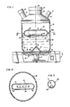
- a base housing 10 of conventional construction and including a motor 11 positioned with its axis vertical, and having connected to the shaft thereof a magnet assembly 12. Magnet assembly 12 will thereby be caused to rotate in a horizontal plane, beneath a seat 13 provided in the upper surface of the base housing 10.
- Various controls may be provided, as is known in the art, for the actuating and stopping of the motor 11, as well as for controlling its speed of rotation.
- a Pearson flask 15 of known construction, including a cylindrical side wall 16, the bottom of Pearson flask 15 having an upstanding conical portion 17 which tapers to a rounded apex 18, thereby forming an interior annular trough or channel 19.
- the axis of the conical portion 17 lies on the central vertical axis 20 through the flask 15.
- the bottom corners of the trough or channel 19 are radiused as shown at 21, so as to form a smooth joining of the vertical side walls and the horizontal bottom 22 of Pearson flask 15.
- Pearson flask 15 is provided with a neck 23 having a cap 24 thereon, which may be of plain, unencumbered construction.
- Access spouts 25 and 26 have caps 27 and 28, respectively, the spouts providing access, if needed, into the interior of the Pearson flask 15, so as to permit additions to or withdrawal of material thereinto.
- These spouts and caps may be unnecessary, since access may be provided to the interior through the neck 23, without interfering with the stirring operation.
- a suitable liquid 29 is contained in Pearson flask 15, having an upper surface 29a exposed to the atmosphere within Pearson flask 15.
- the liquid 29 may be a cell culture medium, and if it is of the type designated as “anchorage dependent", there may be in the liquid 29 a large number of tiny solid beads, called microcarriers.
- cultured cells which are “anchorage independent” do not require the utilization of such microcarriers, and the liquid 29 may be of either type of culture cells, included in a suitable nutrient liquid.
- a buoyant stirrer 30 is provided in the flask 15, which. is preferably of the above noted Pearson flask type.
- the stirrer 30 comprises a hermetically sealed envelope 31 of generally cylindrical shape having hemispherical ends 32.
- the envelope 31 is of a material which is non-corrosive, and which will withstand exposure to wet steam at 123°C. Such materials are known in the art, and include Teflon, Tefzel, Kel-F, and Victrex, these being trademarks of various commercially available plastics.
- Teflon, Tefzel, Kel-F, and Victrex these being trademarks of various commercially available plastics.
- the ability to withstand steam of noted temperature insures that the stirrer 30 may be suitably sterilized.
- a magnet 35 which is in the form of a bar, and may be made up of a plurality of bar magnets placed end to end. As shown in Fig. 3, a suitable adhesive 36 may be utilized to secure the magnet 35 to the interior wall of the envelope 31.
- the density of the stirrer 30 is less than the density of the liquid 29, and is preferably approximately one half of the density of the liquid 29.
- the bar magnet 35 housed within the envelope 31, has its axis generally parallel to the axis of the cylindrical portion of the envelope 31.
- the length of the stirrer 31 is less than the diameter of the Pearson (or other) flask 15.
- the magnetic field from the magnet assembly 12 will cause the stirrer 30 to rotate, generally on the axis 20 of the flask 15, due to magnetic coupling between the magnets of the magnet assembly 12 and the magnet(s) 35.
- the magnetic field will prevent the stirrer 30 from engaging the walls of the Pearson or other flask 15, thereby avoiding crushing of the cells.
- hydrodynamic forces will tend to keep the stirrer 30 centered in the Pearson or other flask 15, avoiding crushing of cells between the stirrer 30 and the walls 16 of flask 15.
- stirrer 30 The stirring action of stirrer 30 on the liquid 29 will serve to keep all of the cells, and microcarriers, if present, in suspension, due to both the primary flow and the secondary flow or motion generated by the construction of the Pearson flask 15.
- the buoyant stirrer 30, located at the top layers of the liquid 29, leaves the bulk of the liquid 29 free of all obstructions, thereby making full use of the viscous drag on the rotating liquid. This also assists in generating the above noted secondary motion which provides for the suspension of the cells and microcarriers, if present.
- viscous drag is harnessed to stir and keep the cells and microcarriers, if present, in suspension.
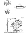
- the stirrer 40 comprises an envelope 41 having bulbous elements 42 at the ends thereof, and connected by a linear portion 43 of generally cylindrical configuration.
- the bulbous elements are, of course, hollow and the envelope 41, as are all of the envelopes herein disclosed, is hermetically sealed.
- the linear portion 43 may be of greater or lesser extent, providing a stirrer 40 of greater or lesser length.
- a bar magnet 44 secured by suitable adhesive 45.
- the bar magnet 44 is seen extending between the polar regions of the two bulbous elements 42, but may be of lesser length, in which case the bar magnet 44 may be adhered to other portions of the envelope 41.
- Fig. 5 there is shown another embodiment of a stirrer designated 50, and having an envelope 51 with a pair of bulbous elements 52.
- a very short linear portion 53 extends between the bulbous elements 52.
- a bar magnet 54 is provided, extending (similar to the construction in Fig. 4) through the linear portion 53 and through the bulbous elements 52, being joined by adhesive 45 to the polar regions of the bulbous elements 52.
- a stirrer 60 comprising a cylindrical, hollow body 61 of magnetically attractable material.
- end caps 62 of any suitable material, secured or adhered to the ends of the body 61, so as to provide a hermetically sealed construction.
- the body 61 being of magnetically attractable material, will be caused to rotate in the same manner as the stirrers hereinabove disclosed.
- the stirrer 60 like the other stirrers, has a density less than the density of the liquid medium in which it is to be used, and so will float therein, as indicated by the line 63, which indicates the liquid surface.
- the body 61 is preferably a hollow magnet.
- a support 70 is provided for a vessel 80.
- the support 70 may be a typical chemical laboratory stand, including a base 71, trunk 72, horizontal arm 73 and clamp 74 of known construction, for engaging and supporting the vessel 80.
- the vessel 80 is of conventional construction, having cylindrical walls 81, and a bottom 82 perpendicular thereto, and with a neck 83 at its upper end, opposite the bottom 82.
- the clamp 74 and the support 70 serve to position and hold the vessel 80 with its axis at an angle of 30° to the horizontal.
- a suitable liquid 84 having a surface 84a.
- the area of surface 84a when the vessel 80 is inclined as above noted, has an area approximately double the area of the surface when the vessel 80 is upright, with its axis vertical.
- a buoyant, magnetic stirrer 30, 40, 50, 60 is contained within the vessel 80 and floats in the upper region of the liquid 84. It is rotated in the manner hereinabove described by the magnetic field of the magnet assembly 12, and will be maintained in position away from the wall 81 of vessel 80 so as to avoid crushing cells and microcarriers.
- the enhanced surface area 84a of the liquid 84 facilitates gas absorption and allows more cells to come to the surface in a given time. This enhances the growth of the cells, accelerating cell production.
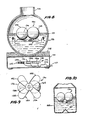
- a base housing 110 having therein a rotating magnetic field generator 112, which include plurality of coil windings 114, 116 and 118, there being, a fourth coil winding not shown in Fig. 8. These four coil windings are connected magnetically to form two electromagnets at right angles to each other and the coils are connected to suitable circuit means 120, connected by conductor 122 to a suitable source of electricity in known manner.
- the rotating magnetic field generator 112 is preferably made as provided in the article Direct Drive Magnetic Stirrers hereinabove referenced.
- a generally spherical flask 125 is shown, having a neck opening 126; the flask 125 preferably has a rounded bottom, but, optionally, a portion of the bottom may be flattened. As shown, the flask 125 has a round bottom, and is supported in a cork ring 128.
- a floating stirrer 130 which may comprise hollow, generally spherical elements 132 and 134. These may be made of a suitable plastic material, such as polypropylene. A suitable hole will have been made in each of the elements 132 and 134, and a bar magnet 136 inserted into the elements 132 and 134, and then the elements are secured together, in a hermetic fashion, thereby encasing the bar magnet 136 in a hermetically sealed, buoyant envelope.
- the elements 132 and 134 may be more or less flattened at their abutting surface portions.
- the buoyant magnetic stirrer 130 comprises, additionally, an impeller 140, for causing upward movement or secondary motion of liquid 129 within flask 124, in which the buoyant magnetic stirrer 130 floats.
- the impeller 140 has, as shown in Fig. 9, four blades 142, 144, 146 and 148, although a greater or lesser number of blades may be utilized.
- the blades 142-148 have a radial extent approximately equal to the length of the assemblage of the elements 132 and 134, and as will be understood, the entire stirrer 130 has dimensions so related to the neck opening 126 that it may pass therethrough.
- the drawings will be understood to be generally descriptive, rather than dimensional.
- a Pearson flask 155 generally of the type disclosed in Fig. 1, and the floating magnetic stirrer with impeller 130 is provided therein.
- the Pearson flask will be seen to have an upstanding conical portion 157, similar to the portion 17, and otherwise generally be the same as and function in the same manner as the Pearson flask shown in Fig. 1.
- the buoyant magnetic stirrer with impeller provides for superior performance, because of the enhancement of the secondary motion which is imparted to the culture medium, upon rotation of the stirrer under the impetus of the rotating magnetic field.
- the buoyant magnetic stirrer may have different embodiments, including a plastic envelope housing one or more bar magnets, the envelope being cylindrical, with hemispherical end portions, or having bulbous elements at the ends, with a linear connecting portion.
- the buoyant magnetic stirrer may be provided with an impeller, to provide an enhanced secondary motion of the culture medium.
- the stirrer may be a cylindrical magnet, hollow and with end closures to provide buoyancy, all of the stirrers being of lesser density than the liquid, preferably having a density of approximately one-half of that of the liquid.
- the herein disclosed buoyant magnetic stirrer may be utilized with a conventional flask, or with a Pearson flask, characterized by a conical projection at the bottom, forming an annular trough or channel in the bottom of the flask.
- the present invention contemplates a method of stirring, using a buoyant stirrer, within a vessel having its axis either vertical, or tilted, preferably at 30° to the horizontal.
- the herein disclosed apparatus and method avoid either submerged bearings or bearings in a cap, thereby avoiding both the damaging of cells and microcarriers, if present, and avoiding a cap with encumberances, making it difficult to clean.
- the herein disclosed carrier is made of material enabling it to withstand sterilization by high temperature wet steam, and there may be enhanced, by the present invention stirrer apparatus and method, the secondary flow or motion and thereby enhancement of the suspension action of the cells in the medium. Where the axis of the vessel is tilted, enhanced exposure of the cells to atmosphere results.
Landscapes
- Health & Medical Sciences (AREA)
- Chemical & Material Sciences (AREA)
- Wood Science & Technology (AREA)
- Organic Chemistry (AREA)
- Life Sciences & Earth Sciences (AREA)
- Engineering & Computer Science (AREA)
- Bioinformatics & Cheminformatics (AREA)
- Zoology (AREA)
- Biomedical Technology (AREA)
- Sustainable Development (AREA)
- Microbiology (AREA)
- Biotechnology (AREA)
- Biochemistry (AREA)
- General Engineering & Computer Science (AREA)
- General Health & Medical Sciences (AREA)
- Genetics & Genomics (AREA)
- Clinical Laboratory Science (AREA)
- Chemical Kinetics & Catalysis (AREA)
- Apparatus Associated With Microorganisms And Enzymes (AREA)
- Mixers With Rotating Receptacles And Mixers With Vibration Mechanisms (AREA)
Claims (18)
Applications Claiming Priority (4)
| Application Number | Priority Date | Filing Date | Title |
|---|---|---|---|
| US38676482A | 1982-06-09 | 1982-06-09 | |
| US386764 | 1982-06-09 | ||
| US432128 | 1982-09-29 | ||
| US06/432,128 US4498785A (en) | 1982-06-09 | 1982-09-30 | Floating magnetic stirrer for culture medium |
Publications (3)
| Publication Number | Publication Date |
|---|---|
| EP0105574A2 EP0105574A2 (fr) | 1984-04-18 |
| EP0105574A3 EP0105574A3 (en) | 1984-06-06 |
| EP0105574B1 true EP0105574B1 (fr) | 1990-01-10 |
Family
ID=27011586
Family Applications (1)
| Application Number | Title | Priority Date | Filing Date |
|---|---|---|---|
| EP83303260A Expired EP0105574B1 (fr) | 1982-06-09 | 1983-06-06 | Mélangeur magnétique flottant pour milieu de culture |
Country Status (5)
| Country | Link |
|---|---|
| US (1) | US4498785A (fr) |
| EP (1) | EP0105574B1 (fr) |
| JP (1) | JPS5948071A (fr) |
| DE (1) | DE3381084D1 (fr) |
| GB (1) | GB2123706B (fr) |
Families Citing this family (67)
| Publication number | Priority date | Publication date | Assignee | Title |
|---|---|---|---|---|
| JPS59206034A (ja) * | 1983-05-09 | 1984-11-21 | テクネ コーポレーション | 浮游性磁気撹拌子を用いた撹拌装置および撹拌方法 |
| US4465377A (en) * | 1983-06-07 | 1984-08-14 | Techne Corporation | Magnetic stirrer apparatus with guided, floating stirrer |
| CH665217A5 (de) * | 1985-02-15 | 1988-04-29 | Agrogen Stiftung | Verfahren und vorrichtung zur in vitro kultur von pflanzenzellen, pflanzengeweben, pflanzenorganen, pflanzenteilen sowie zur mikropropagation und regeneration von ganzen pflanzen. |
| US4759635A (en) * | 1985-08-08 | 1988-07-26 | Techne Corporation | Magnetic stirrer apparatus with improved stirring action |
| GB2178971B (en) * | 1985-08-08 | 1989-02-15 | Techne Inc | Magnetic stirrer apparatus with improved stirring action |
| DE3761205D1 (de) * | 1986-03-10 | 1990-01-25 | Solly Katz | Ausgeber fuer fluessigkeiten. |
| US4760028A (en) * | 1986-07-25 | 1988-07-26 | Techne Incorporated | Bioreactor apparatus with surface aerator screen |
| US4836826A (en) * | 1987-12-18 | 1989-06-06 | The United States Of America As Represented By The Administrator Of The National Aeronautics And Space Administration | Magnetic drive coupling |
| US5267791A (en) * | 1991-12-13 | 1993-12-07 | Corning Incorporated | Suspended cell culture stirring vessel closure and apparatus |
| DE4403967C2 (de) * | 1993-02-10 | 2002-04-18 | Biosyntan Ges Fuer Bioorg Synt | Verfahren und Vorrichtung zur Herstellung von Peptiden, Peptoiden und Oligonukleotiden und deren Verwendung |
| JP3349248B2 (ja) * | 1994-03-22 | 2002-11-20 | 千寿製薬株式会社 | 流通型角膜透過実験器具およびこの実験器具を用いた実験装置 |
| US6416215B1 (en) | 1999-12-14 | 2002-07-09 | University Of Kentucky Research Foundation | Pumping or mixing system using a levitating magnetic element |
| US6758593B1 (en) | 2000-10-09 | 2004-07-06 | Levtech, Inc. | Pumping or mixing system using a levitating magnetic element, related system components, and related methods |
| CN1190486C (zh) * | 2000-05-18 | 2005-02-23 | 周镭 | 菌体培养装置和方法及采用此类装置的菌体培养系统 |
| US6733171B2 (en) * | 2000-09-13 | 2004-05-11 | Levitronix Llc | Magnetic stirring apparatus and an agitating device |
| US7762716B2 (en) * | 2000-10-09 | 2010-07-27 | Levtech, Inc. | Mixing vessel with a fluid-agitating element supported by a roller bearing |
| US8182137B2 (en) | 2000-10-09 | 2012-05-22 | Atmi Packaging, Inc. | Mixing bag or vessel with a fluid-agitating element |
| US6837613B2 (en) * | 2001-04-10 | 2005-01-04 | Levtech, Inc. | Sterile fluid pumping or mixing system and related method |
| US7086778B2 (en) * | 2000-10-09 | 2006-08-08 | Levtech, Inc. | System using a levitating, rotating pumping or mixing element and related methods |
| AU2002239504A1 (en) * | 2000-12-06 | 2002-06-18 | Pharmacia Corporation | Laboratory scale milling process |
| US7211430B2 (en) * | 2001-08-03 | 2007-05-01 | Becton, Dickinson And Company | System for stirring growth medium |
| JP4645033B2 (ja) * | 2001-10-03 | 2011-03-09 | リーブテック,インコーポレイテッド | 流体撹拌素子のための受け器を有する混合用袋又は容器 |
| US20040131500A1 (en) * | 2002-01-18 | 2004-07-08 | Chow Herbert S. | Device and method for evaluating platelets |
| US6981794B2 (en) * | 2002-04-12 | 2006-01-03 | Hynetics Llc | Methods for mixing solutions |
| US6923567B2 (en) * | 2002-04-12 | 2005-08-02 | Hynetics Llc | Mixing tank assembly |
| US6908223B2 (en) | 2002-04-12 | 2005-06-21 | Hynetics Llc | Systems for mixing liquid solutions and methods of manufacture |
| US6988825B2 (en) * | 2002-07-03 | 2006-01-24 | Bio/Data Corporation | Method and apparatus for using vertical magnetic stirring to produce turbulent and chaotic mixing in various states, without compromising components |
| US7153021B2 (en) * | 2003-03-28 | 2006-12-26 | Hyclone Laboratories, Inc. | Container systems for mixing fluids with a magnetic stir bar |
| US20040248291A1 (en) * | 2003-04-10 | 2004-12-09 | Pentax Corporation | Method for culturing cells, cell culture carriers and cell culture apparatus |
| JP2007522801A (ja) * | 2004-01-07 | 2007-08-16 | リーブテック,インコーポレイテッド | 一体のスパージャーとセンサー受け器を有する混合用袋 |
| EP2551676A1 (fr) * | 2005-03-28 | 2013-01-30 | Becton, Dickinson and Company | Installation et procédé pour l'agitation de solides en suspension dans un milieu liquide |
| JP2007020387A (ja) * | 2005-06-07 | 2007-01-25 | Maguneo Giken:Kk | 超伝導非接触回転装置 |
| WO2008040567A1 (fr) * | 2006-10-03 | 2008-04-10 | Artelis | Sac mélangeur souple, dispositif mélangeur et système mélangeur associé |
| JP2009513140A (ja) * | 2005-10-26 | 2009-04-02 | リーブテック,インコーポレイテッド | ミキサーとスパージャーを備えたバイオリアクター |
| SG10201503987WA (en) * | 2006-05-13 | 2015-06-29 | Pall Life Sciences Belgium | Disposable Bioreactor |
| EP2114554A1 (fr) * | 2007-02-21 | 2009-11-11 | Levtech Inc. | Roulement à rouleaux pour élément agitateur de fluide et récipient associé |
| US7828968B2 (en) * | 2007-08-30 | 2010-11-09 | Veridex, Llc | Method and apparatus for imaging target components in a biological sample using permanent magnets |
| US8110101B2 (en) | 2007-08-30 | 2012-02-07 | Veridex, Llc | Method and apparatus for imaging target components in a biological sample using permanent magnets |
| RU2528102C2 (ru) * | 2008-09-05 | 2014-09-10 | Конинклейке Филипс Электроникс Н.В. | Вращающееся магнитное поле для улучшенного детектирования при анализе кластеров |
| MX2013009620A (es) | 2011-02-25 | 2014-05-27 | Algenol Biofuels Inc | Sistema magneticamente acoplado para mezclado. |
| DE102011114191A1 (de) * | 2011-09-22 | 2013-03-28 | Eagleburgmann Germany Gmbh & Co. Kg | Spalttopf für eine Magnetkupplung mit verbesserter Fluidströmung |
| US9339026B2 (en) | 2012-06-14 | 2016-05-17 | Therapeutic Proteins International, LLC | Pneumatically agitated and aerated single-use bioreactor |
| CH707442A1 (de) * | 2013-01-14 | 2014-07-15 | Hochschule Rapperswil Inst Für Umwelt Und Verfahrenstechnik | Vorrichtung zur Achsenstabilisierung von rotierenden Elementen. |
| US9790465B2 (en) | 2013-04-30 | 2017-10-17 | Corning Incorporated | Spheroid cell culture well article and methods thereof |
| US20140334249A1 (en) * | 2013-05-08 | 2014-11-13 | Roxi Group, Inc. | Beverage mixing, storing and dispensing apparatus |
| KR101609327B1 (ko) | 2013-05-16 | 2016-04-08 | 유제형 | 교반 기능을 갖는 용기 시스템 |
| CA2915507A1 (fr) | 2013-06-28 | 2014-12-31 | Saint-Gobain Performance Plastics Corporation | Ensembles de melange comprenant des roues magnetiques |
| US11944946B2 (en) | 2013-06-28 | 2024-04-02 | Saint-Gobain Performance Plastics Corporation | Mixing assemblies including magnetic impellers |
| CN103638856B (zh) * | 2013-12-04 | 2015-11-11 | 西北大学 | 磁子悬浮式磁力搅拌器 |
| WO2015095892A1 (fr) * | 2013-12-20 | 2015-06-25 | Pbs Biotech, Inc. | Bioréacteur de mélange vertical et système d'entraînement associé |
| SG11201703493SA (en) | 2014-10-29 | 2017-05-30 | Corning Inc | Cell culture insert |
| JP2017532971A (ja) | 2014-10-29 | 2017-11-09 | コーニング インコーポレイテッド | 細胞培養集合体を生成するためのマイクロウェル設計および製造 |
| US10583409B2 (en) * | 2016-03-31 | 2020-03-10 | General Electric Company | Axial flux stator |
| US11097236B2 (en) | 2016-03-31 | 2021-08-24 | Global Life Sciences Solutions Usa Llc | Magnetic mixers |
| CN106282013B (zh) * | 2016-09-09 | 2018-06-01 | 东北农业大学 | 一种便于微生物紫外线诱变的装置 |
| US9873097B1 (en) | 2017-07-12 | 2018-01-23 | Boris Dushine | Magnetic stirring system for wine aeration and method of using same |
| JP7245222B2 (ja) | 2017-07-14 | 2023-03-23 | コーニング インコーポレイテッド | 手動又は自動で培地を交換するための3d細胞培養容器 |
| US11857970B2 (en) | 2017-07-14 | 2024-01-02 | Corning Incorporated | Cell culture vessel |
| US10881135B1 (en) | 2017-11-10 | 2021-01-05 | Creative Destruction, LLC | Cyclonically cooled and filtered smoking water pipe and method |
| WO2019226831A1 (fr) * | 2018-05-22 | 2019-11-28 | Gate Scientific, Inc. | Détection sans fil de propriétés d'un environnement fermé et dispositifs associés |
| JP7171695B2 (ja) | 2018-07-13 | 2022-11-15 | コーニング インコーポレイテッド | 液体培地送達面を含む側壁を有するマイクロキャビティ皿 |
| JP7171696B2 (ja) | 2018-07-13 | 2022-11-15 | コーニング インコーポレイテッド | 相互接続されたウェルを有するマイクロプレートを備えた流体デバイス |
| PL3649229T3 (pl) | 2018-07-13 | 2021-12-06 | Corning Incorporated | Naczynia do hodowli komórkowych ze stabilizującymi urządzeniami |
| US10350561B1 (en) | 2018-08-03 | 2019-07-16 | Boris Dushine | Magnetic stirring system for wine aeration and method of using same |
| US10220361B1 (en) | 2018-08-03 | 2019-03-05 | Boris Dushine | Magnetic stirring system for the automated and optimized reconstitution of powdered infant formulations and methods of using same |
| CN109550451B (zh) * | 2018-09-30 | 2021-03-12 | 中国水利水电科学研究院 | 一种节能高效的脱硫用制浆装置 |
| TWI809833B (zh) * | 2022-04-22 | 2023-07-21 | 牟敦剛 | 磁性耦合方法以及磁性耦合攪動及其裝置 |
Family Cites Families (11)
| Publication number | Priority date | Publication date | Assignee | Title |
|---|---|---|---|---|
| US2036076A (en) * | 1934-09-22 | 1936-03-31 | Carl A Philippl | Toy or game |
| US2350534A (en) * | 1942-10-05 | 1944-06-06 | Rosinger Arthur | Magnetic stirrer |
| US2770073A (en) * | 1954-06-21 | 1956-11-13 | William J Sullivan | Animated display device |
| US3172645A (en) * | 1961-07-21 | 1965-03-09 | Doryce Appleton | Agitator for foods of a liquid form containing solids |
| US3245665A (en) * | 1964-03-18 | 1966-04-12 | Arthur H Thomas Company | Magnetic mixing bar |
| DE2444328A1 (de) * | 1974-09-17 | 1976-03-25 | Wolfgang Gruhn | Verfahren zur bewegung von fluessigkeiten, gasen, granulaten oder staeuben, sowie zum antrieb leistungsarmer geraete mittels elektromagnetisch fererregter rotationsoder schwingkoerper |
| JPS55147143A (en) * | 1979-03-29 | 1980-11-15 | Toyo Eng Corp | Agitation method |
| GB2053704A (en) * | 1979-07-17 | 1981-02-11 | Techne Cambridge Ltd | A flask for use in stirring particles in suspension such as microcarriers for anchorage-dependent living cells in a liquid culture medium |
| GB2062481A (en) * | 1979-11-07 | 1981-05-28 | Techne Cambridge Ltd | Stirring apparatus |
| GB2082930B (en) * | 1980-08-27 | 1984-02-22 | Thomas Thomas Ronald | Magnetic stirring element |
| JPS6010775B2 (ja) * | 1982-01-06 | 1985-03-20 | 正信 井口 | 磁気撹拌機における回転撹拌用浮遊磁性体 |
-
1982
- 1982-09-30 US US06/432,128 patent/US4498785A/en not_active Expired - Fee Related
-
1983
- 1983-06-06 EP EP83303260A patent/EP0105574B1/fr not_active Expired
- 1983-06-06 DE DE8383303260T patent/DE3381084D1/de not_active Expired - Lifetime
- 1983-06-09 GB GB08315883A patent/GB2123706B/en not_active Expired
- 1983-06-09 JP JP58104836A patent/JPS5948071A/ja active Pending
Also Published As
| Publication number | Publication date |
|---|---|
| GB8315883D0 (en) | 1983-07-13 |
| JPS5948071A (ja) | 1984-03-19 |
| DE3381084D1 (de) | 1990-02-15 |
| EP0105574A3 (en) | 1984-06-06 |
| GB2123706A (en) | 1984-02-08 |
| GB2123706B (en) | 1986-09-03 |
| US4498785A (en) | 1985-02-12 |
| EP0105574A2 (fr) | 1984-04-18 |
Similar Documents
| Publication | Publication Date | Title |
|---|---|---|
| US4498785A (en) | Floating magnetic stirrer for culture medium | |
| US4759635A (en) | Magnetic stirrer apparatus with improved stirring action | |
| JPS60160882A (ja) | 発酵および組織培養容器用に適した撹拌器 | |
| US3854704A (en) | Magnetic cell stirrer | |
| US20100041095A1 (en) | Pneumatic bioreactor | |
| US4465377A (en) | Magnetic stirrer apparatus with guided, floating stirrer | |
| US4450076A (en) | Small-sample dialyzer | |
| US4382685A (en) | Method and apparatus for stirring particles in suspension such as microcarriers for anchorage-dependent living cells in a liquid culture medium | |
| US10081787B2 (en) | Vertical wheel bioreactors | |
| US4162855A (en) | Magnetic stirrer apparatus | |
| US3900186A (en) | Magnetic cell stirrer | |
| US6109780A (en) | Dynamic vortex impeller | |
| US20030053371A1 (en) | Magnetic stirring apparatus and an agitating device | |
| US4760028A (en) | Bioreactor apparatus with surface aerator screen | |
| JP2004534544A (ja) | 使い捨て容器 | |
| EP0053869B1 (fr) | Méthode et appareil pour l'agitation de particules en suspension, par exemple de microsupports pour des cellules vivantes liées par ancrage, dans un milieu de culture liquide | |
| US5846817A (en) | Bioreactor, in particular for microgravity | |
| JP2005151812A (ja) | 浮遊攪拌培養装置 | |
| EP0124970A2 (fr) | Mélangeur magnétique et procédé de mélange | |
| WO1998006485A1 (fr) | Appareil agitateur | |
| JP2005013112A (ja) | 浮遊攪拌培養装置 | |
| JPS6221312Y2 (fr) | ||
| JPH06261747A (ja) | 細胞の液体培養方法及び培養装置 | |
| GB2178971A (en) | Floating magnetic stirrer for culture medium | |
| JPH0347068A (ja) | 植物組織培養槽 |
Legal Events
| Date | Code | Title | Description |
|---|---|---|---|
| PUAI | Public reference made under article 153(3) epc to a published international application that has entered the european phase |
Free format text: ORIGINAL CODE: 0009012 |
|
| PUAL | Search report despatched |
Free format text: ORIGINAL CODE: 0009013 |
|
| AK | Designated contracting states |
Designated state(s): DE FR GB |
|
| AK | Designated contracting states |
Designated state(s): DE FR GB |
|
| 17P | Request for examination filed |
Effective date: 19841204 |
|
| RBV | Designated contracting states (corrected) |
Designated state(s): DE FR |
|
| GRAA | (expected) grant |
Free format text: ORIGINAL CODE: 0009210 |
|
| AK | Designated contracting states |
Kind code of ref document: B1 Designated state(s): DE FR |
|
| REF | Corresponds to: |
Ref document number: 3381084 Country of ref document: DE Date of ref document: 19900215 |
|
| ET | Fr: translation filed | ||
| PGFP | Annual fee paid to national office [announced via postgrant information from national office to epo] |
Ref country code: FR Payment date: 19900613 Year of fee payment: 8 |
|
| PGFP | Annual fee paid to national office [announced via postgrant information from national office to epo] |
Ref country code: DE Payment date: 19900629 Year of fee payment: 8 |
|
| PLBE | No opposition filed within time limit |
Free format text: ORIGINAL CODE: 0009261 |
|
| STAA | Information on the status of an ep patent application or granted ep patent |
Free format text: STATUS: NO OPPOSITION FILED WITHIN TIME LIMIT |
|
| 26N | No opposition filed | ||
| PG25 | Lapsed in a contracting state [announced via postgrant information from national office to epo] |
Ref country code: FR Effective date: 19920228 |
|
| PG25 | Lapsed in a contracting state [announced via postgrant information from national office to epo] |
Ref country code: DE Effective date: 19920401 |
|
| REG | Reference to a national code |
Ref country code: FR Ref legal event code: ST |