EP0105585B1 - Brûleur pour combustible gazeux - Google Patents
Brûleur pour combustible gazeux Download PDFInfo
- Publication number
- EP0105585B1 EP0105585B1 EP83304643A EP83304643A EP0105585B1 EP 0105585 B1 EP0105585 B1 EP 0105585B1 EP 83304643 A EP83304643 A EP 83304643A EP 83304643 A EP83304643 A EP 83304643A EP 0105585 B1 EP0105585 B1 EP 0105585B1
- Authority
- EP
- European Patent Office
- Prior art keywords
- burner
- passageways
- roof element
- gas
- vertical
- Prior art date
- Legal status (The legal status is an assumption and is not a legal conclusion. Google has not performed a legal analysis and makes no representation as to the accuracy of the status listed.)
- Expired
Links
Images


Classifications
-
- F—MECHANICAL ENGINEERING; LIGHTING; HEATING; WEAPONS; BLASTING
- F23—COMBUSTION APPARATUS; COMBUSTION PROCESSES
- F23D—BURNERS
- F23D14/00—Burners for combustion of a gas, e.g. of a gas stored under pressure as a liquid
- F23D14/46—Details
- F23D14/48—Nozzles
- F23D14/58—Nozzles characterised by the shape or arrangement of the outlet or outlets from the nozzle, e.g. of annular configuration
Definitions
- the present invention relates to burners for gaseous fuel comprising a body defining a plenum chamber, the body being adapted to receive fuel and primary air, in use, said body including a roof element having a plurality of relatively narrow passageways defined therein from the chamber to the exterior of the burner.
- Such burners are particularly for use in domestic or industrial gas ranges using town or bottled gas.
- the technical problem to be solved by the present invention is the provision of a flame that will provide efficient combustion.
- the burner of the present invention is characterised in that said passages are substantially straight and are inclined upwardly and inwardly to the exterior of the burner at a common predetermined angle to a plane perpendicular to the vertical axis of the burner, and in that a respective vertical plane passing through each passageway is tangential to an imaginary vertical cylinder passing through the centre of said burner.
- Such a burner produces a substantially vertical cylindrical rotating flame structure.
- This type of flame structure is secondary air as a function of the velocity of the gas/primary air mixture and therefore reduces the coefficient of air excess, thus promoting the fuel combustion process and intensifying heat exchange, while reducing wasteful radiation.
- the rotating concentrated flame is produced by the interaction of the plurality of gas/primary air jets forced to leave the plenum chamber via passageways which impart to these jets an upward and inward, as well as a tangential component.
- Hitting the flat surface to be heated, the quasi-helical path described by the flames is turned into a flat, multi-arm spiral, the length of each arm of which exceeds the length of the straight path along which the combustion products of conventional burners move. This of course enhances heat transfer and reduces heat losses.
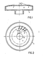
- a burner body 1 mountable on a standard venturi and nozzle unit (not shown), which, in conjunction with a roof plate 4, defines and delimits a plenum chamber 6.
- This roof element or plate 4 which, for purpose of cleaning of the entire burner, is advantageously detachable from the burner body 2, is provided with a plurality of passageways for the gas/primary air mixture to be turned.
- these passageways are in the form of uniformly spaced holes 8 of a circular cross-section. As can be seen in Figure 1, these holes 8 lead from the plenum chamber 6 upwards and inwards, emerging on the upper face of the roof plate 4.
- the angle ⁇ which these holes 8 include with the horizontal for optimal operation may vary between 15° and 40°.
- vertical planes passing through the centre of the holes 8 are not radial, but tangential to an imaginary vertical cylinder 10.
- the angle a included between these vertical planes and the corresponding radial planes passing through the centre of the plenum-side openings may vary between 10° and 35° for optimal operation.
- this "double slant" of the holes produces a vertical, rotating flame “column” or vortex, the low-pressure zone inside which draws in the necessary secondary air, which constitutes about half of the combustion air required, the other half being constituted by the primary air reaching the plenum chamber 6 together with the gas.
- FIGs 3 to 5 illustrate another design of burner.
- a burner body 2 which, basically, is similar to that of the previous embodiment.
- the roof plate 4 is different in that the passageways for the gas/primary air mixture are not holes, but grooves 12 which are milled into the tapering surface of the roof plate 4.
- these grooves 12 have a rounded bottom, as is dear from the shape produced where these grooves 12 break into the top surface 14 of the roof plate 4.
- These open grooves 12 are turned into passageways by being covered by a cover plate 16, the inside taper 18 of which fits the tapering surface of the roof plate 4.
- This embodiment is characterised by the "double slant" a and (3 of the passageways for the gas/primary air mixture.
- Figure 5 also clearly shows the imaginary cylinder 10 defining the angle a.
- a third burner is shown in Figures 6 and 7. While this burner incorporates the burner of Figures 1 and 2 in its entirety, it comprises two novel features, one being a plurality of fins 20 arranged on the peripheral zone of the outside surface and oriented in such a way as to lie within the above-mentioned vertical planes tangent to the imaginary cylinder 10. These fins 20 serve to guide as well as preheat the secondary air drawn in by the rotary flame as explained above.
- the second novel feature is a plurality of relatively thin pins 22 mounted on the burner roof plate 4, in proximity to the points where the holes 8 emerge on the roof plate 4.
- pins 22 are made from a material having catalytic properties, such as heat-resistant steel alloyed with certain heavy metals such as nickel, chromium or the like, which promote complete combustion of carbon monoxide (CO).
- a material having catalytic properties such as heat-resistant steel alloyed with certain heavy metals such as nickel, chromium or the like, which promote complete combustion of carbon monoxide (CO).
Landscapes
- Engineering & Computer Science (AREA)
- Chemical & Material Sciences (AREA)
- Combustion & Propulsion (AREA)
- Mechanical Engineering (AREA)
- General Engineering & Computer Science (AREA)
- Pre-Mixing And Non-Premixing Gas Burner (AREA)
- Gas Burners (AREA)
Claims (5)
Priority Applications (1)
| Application Number | Priority Date | Filing Date | Title |
|---|---|---|---|
| AT83304643T ATE27652T1 (de) | 1982-08-13 | 1983-08-11 | Brenner fuer gasfoermigen brennstoff. |
Applications Claiming Priority (2)
| Application Number | Priority Date | Filing Date | Title |
|---|---|---|---|
| IL66538 | 1982-08-13 | ||
| IL66538A IL66538A (en) | 1982-08-13 | 1982-08-13 | Burner for gaseous fuel |
Publications (2)
| Publication Number | Publication Date |
|---|---|
| EP0105585A1 EP0105585A1 (fr) | 1984-04-18 |
| EP0105585B1 true EP0105585B1 (fr) | 1987-06-03 |
Family
ID=11053692
Family Applications (1)
| Application Number | Title | Priority Date | Filing Date |
|---|---|---|---|
| EP83304643A Expired EP0105585B1 (fr) | 1982-08-13 | 1983-08-11 | Brûleur pour combustible gazeux |
Country Status (7)
| Country | Link |
|---|---|
| US (1) | US4583941A (fr) |
| EP (1) | EP0105585B1 (fr) |
| AT (1) | ATE27652T1 (fr) |
| AU (1) | AU556748B2 (fr) |
| DE (1) | DE3371940D1 (fr) |
| ES (1) | ES282311Y (fr) |
| IL (1) | IL66538A (fr) |
Families Citing this family (20)
| Publication number | Priority date | Publication date | Assignee | Title |
|---|---|---|---|---|
| GB2219071B (en) * | 1988-05-28 | 1992-04-22 | Terry Roberts | Atmospheric gas burner |
| ES2076098B1 (es) * | 1993-07-30 | 1998-05-01 | Ind Belseher S L | Dispositivo quemador de gas |
| JP4320476B2 (ja) * | 1997-09-17 | 2009-08-26 | 横井産業株式会社 | 流体の微流量送給構造 |
| US6619280B1 (en) | 2002-05-30 | 2003-09-16 | Dongsheng Zhou | Converging flame burner |
| ATE410100T1 (de) * | 2002-06-25 | 2008-10-15 | Jetboil Inc | Erhitzungsgerät |
| USD523684S1 (en) | 2003-06-25 | 2006-06-27 | Jetboil, Inc. | Heating vessel with support |
| US20060147865A1 (en) * | 2005-01-05 | 2006-07-06 | Charles Czajka | Cooking range burner head assembly |
| US7363923B2 (en) * | 2005-01-05 | 2008-04-29 | Illinois Tool Works Inc. | cooking range assembly and monolithic drip pan |
| US7811082B2 (en) * | 2005-01-05 | 2010-10-12 | Premark Feg, Llc | Gas circuit and pilot light system for cooking range |
| US20100154776A1 (en) * | 2005-01-05 | 2010-06-24 | Charles Czajka | Cooking range burner head assembly |
| US7458618B2 (en) * | 2005-01-18 | 2008-12-02 | Fm Global Technologies | Fixed flange spray deflector |
| RU2307286C2 (ru) * | 2005-11-08 | 2007-09-27 | Виталий Николаевич Ключник | Горелка газовая |
| CN100520177C (zh) * | 2006-03-21 | 2009-07-29 | 周建基 | 一种燃烧器火盖的制造方法 |
| JP4873549B2 (ja) * | 2006-07-28 | 2012-02-08 | 株式会社パロマ | ガスコンロ |
| US20080029082A1 (en) * | 2006-08-04 | 2008-02-07 | Dowst W Perry | Interchangeable system for high-efficiency heating and cooking |
| US9541294B2 (en) | 2013-08-06 | 2017-01-10 | Whirlpool Corporation | Inner swirling flame gas burner |
| USD791930S1 (en) | 2015-06-04 | 2017-07-11 | Tropitone Furniture Co., Inc. | Fire burner |
| US10197291B2 (en) | 2015-06-04 | 2019-02-05 | Tropitone Furniture Co., Inc. | Fire burner |
| US10436451B2 (en) | 2016-10-06 | 2019-10-08 | Whirlpool Corporation | Cap to change inner flame burner to vertical flame |
| CN108425304A (zh) * | 2018-06-07 | 2018-08-21 | 重庆而为路面材料有限公司 | 一种温拌沥青混凝土生产装置 |
Family Cites Families (12)
| Publication number | Priority date | Publication date | Assignee | Title |
|---|---|---|---|---|
| US602041A (en) * | 1898-04-05 | Peter g | ||
| US478295A (en) * | 1892-07-05 | george h | ||
| US794545A (en) * | 1905-04-14 | 1905-07-11 | Thomas W Phillips Jr | Fuel-burner. |
| US951394A (en) * | 1908-04-06 | 1910-03-08 | Arthur E Hauck | Oil-burner. |
| US1130132A (en) * | 1914-06-01 | 1915-03-02 | Frank Antonuccio | Burner. |
| US1757023A (en) * | 1926-10-20 | 1930-05-06 | Ira E Smith | Oil burner |
| US2384022A (en) * | 1941-04-22 | 1945-09-04 | Selas Corp Of America | Gas burner |
| DE843744C (de) * | 1949-03-19 | 1952-07-14 | Theodor Kayser | Brenner fuer Gaskocher |
| GB712089A (en) * | 1952-12-22 | 1954-07-14 | Matsutaro Suda | Improvements in or relating to gas burners |
| US3022815A (en) * | 1958-03-31 | 1962-02-27 | Bloom Eng Co Inc | Burner mechanism |
| JPS599010B2 (ja) * | 1978-09-14 | 1984-02-28 | 株式会社道前築炉工業 | 気体燃焼方法 |
| US4419074A (en) * | 1981-09-11 | 1983-12-06 | Advanced Mechanical Technology, Inc. | High efficiency gas burner |
-
1982
- 1982-08-13 IL IL66538A patent/IL66538A/xx not_active IP Right Cessation
-
1983
- 1983-08-11 DE DE8383304643T patent/DE3371940D1/de not_active Expired
- 1983-08-11 EP EP83304643A patent/EP0105585B1/fr not_active Expired
- 1983-08-11 AT AT83304643T patent/ATE27652T1/de not_active IP Right Cessation
- 1983-08-12 US US06/522,532 patent/US4583941A/en not_active Expired - Lifetime
- 1983-08-12 ES ES1983282311U patent/ES282311Y/es not_active Expired
- 1983-12-30 AU AU23002/83A patent/AU556748B2/en not_active Ceased
Also Published As
| Publication number | Publication date |
|---|---|
| US4583941A (en) | 1986-04-22 |
| ATE27652T1 (de) | 1987-06-15 |
| IL66538A0 (en) | 1982-12-31 |
| AU2300283A (en) | 1985-07-04 |
| ES282311Y (es) | 1985-11-01 |
| AU556748B2 (en) | 1986-11-20 |
| DE3371940D1 (en) | 1987-07-09 |
| IL66538A (en) | 1985-07-31 |
| EP0105585A1 (fr) | 1984-04-18 |
| ES282311U (es) | 1985-04-01 |
Similar Documents
| Publication | Publication Date | Title |
|---|---|---|
| EP0105585B1 (fr) | Brûleur pour combustible gazeux | |
| US6655954B2 (en) | Gas burner and cooking apparatus using such a burner | |
| US5197456A (en) | Gas water heater with improved exhaust distribution in multiple flues | |
| EP2390569B1 (fr) | Brûleur pour cuisinières à gaz professionnelles ou domestiques, particulièrement les brûleurs à flamme verticale adaptés à la cuisson de woks et similaire | |
| US5437262A (en) | Burner apparatus | |
| CN101556058B (zh) | 通风塔式下进风燃气灶 | |
| US5197872A (en) | Concentric burner set for glass-ceramic gas cooker top | |
| JP2003166718A (ja) | ガスコンロ | |
| CN118328389A (zh) | 燃烧器及燃气灶 | |
| KR102456435B1 (ko) | 외기 유입형 화로대 | |
| CN212132581U (zh) | 一种燃气炉头的聚能盘与燃烧器结构 | |
| CN217635604U (zh) | 一种防风且提高燃烧效率的燃烧器 | |
| US1962756A (en) | Gas burner | |
| CN115280072A (zh) | 用于高热效率燃烧lpg燃料的家用烹饪炉 | |
| CN216744347U (zh) | 一种外环火盖、燃烧器及燃气灶 | |
| JP2739012B2 (ja) | ポット式石油バーナ | |
| CN218721484U (zh) | 火盖和具有其的燃烧器 | |
| CN1069562A (zh) | 煤气灶压盖式环孔旋流焦中燃烧器 | |
| CN222417451U (zh) | 内环火盖、燃烧器及燃气灶 | |
| CN223036404U (zh) | 一种分气座、燃烧器及灶具 | |
| CN218410004U (zh) | 一种防风的搪瓷铸铁炉架 | |
| CN215723191U (zh) | 一种高速均流式燃烧器燃气系统 | |
| CN2275685Y (zh) | 旋转火焰燃烧器 | |
| JPS60129514A (ja) | ガスバ−ナ− | |
| JPS6119303Y2 (fr) |
Legal Events
| Date | Code | Title | Description |
|---|---|---|---|
| PUAI | Public reference made under article 153(3) epc to a published international application that has entered the european phase |
Free format text: ORIGINAL CODE: 0009012 |
|
| AK | Designated contracting states |
Designated state(s): AT BE CH DE FR GB IT LI NL SE |
|
| 17P | Request for examination filed |
Effective date: 19841010 |
|
| GRAA | (expected) grant |
Free format text: ORIGINAL CODE: 0009210 |
|
| AK | Designated contracting states |
Kind code of ref document: B1 Designated state(s): AT BE CH DE FR GB IT LI NL SE |
|
| REF | Corresponds to: |
Ref document number: 27652 Country of ref document: AT Date of ref document: 19870615 Kind code of ref document: T |
|
| REF | Corresponds to: |
Ref document number: 3371940 Country of ref document: DE Date of ref document: 19870709 |
|
| ET | Fr: translation filed | ||
| ITF | It: translation for a ep patent filed | ||
| PLBE | No opposition filed within time limit |
Free format text: ORIGINAL CODE: 0009261 |
|
| STAA | Information on the status of an ep patent application or granted ep patent |
Free format text: STATUS: NO OPPOSITION FILED WITHIN TIME LIMIT |
|
| 26N | No opposition filed | ||
| ITTA | It: last paid annual fee | ||
| PGFP | Annual fee paid to national office [announced via postgrant information from national office to epo] |
Ref country code: GB Payment date: 19940805 Year of fee payment: 12 |
|
| PGFP | Annual fee paid to national office [announced via postgrant information from national office to epo] |
Ref country code: FR Payment date: 19940809 Year of fee payment: 12 |
|
| PGFP | Annual fee paid to national office [announced via postgrant information from national office to epo] |
Ref country code: AT Payment date: 19940812 Year of fee payment: 12 |
|
| PGFP | Annual fee paid to national office [announced via postgrant information from national office to epo] |
Ref country code: CH Payment date: 19940815 Year of fee payment: 12 |
|
| PGFP | Annual fee paid to national office [announced via postgrant information from national office to epo] |
Ref country code: DE Payment date: 19940816 Year of fee payment: 12 |
|
| PGFP | Annual fee paid to national office [announced via postgrant information from national office to epo] |
Ref country code: SE Payment date: 19940817 Year of fee payment: 12 |
|
| PGFP | Annual fee paid to national office [announced via postgrant information from national office to epo] |
Ref country code: NL Payment date: 19940831 Year of fee payment: 12 |
|
| PGFP | Annual fee paid to national office [announced via postgrant information from national office to epo] |
Ref country code: BE Payment date: 19941012 Year of fee payment: 12 |
|
| EAL | Se: european patent in force in sweden |
Ref document number: 83304643.6 |
|
| PG25 | Lapsed in a contracting state [announced via postgrant information from national office to epo] |
Ref country code: GB Effective date: 19950811 Ref country code: AT Effective date: 19950811 |
|
| PG25 | Lapsed in a contracting state [announced via postgrant information from national office to epo] |
Ref country code: SE Effective date: 19950812 |
|
| PG25 | Lapsed in a contracting state [announced via postgrant information from national office to epo] |
Ref country code: LI Effective date: 19950831 Ref country code: CH Effective date: 19950831 Ref country code: BE Effective date: 19950831 |
|
| BERE | Be: lapsed |
Owner name: BEN-GURION UNIVERSITY OF THE NEGEV RESEARCH AND D Effective date: 19950831 |
|
| PG25 | Lapsed in a contracting state [announced via postgrant information from national office to epo] |
Ref country code: NL Effective date: 19960301 |
|
| GBPC | Gb: european patent ceased through non-payment of renewal fee |
Effective date: 19950811 |
|
| REG | Reference to a national code |
Ref country code: CH Ref legal event code: PL |
|
| PG25 | Lapsed in a contracting state [announced via postgrant information from national office to epo] |
Ref country code: FR Effective date: 19960430 |
|
| NLV4 | Nl: lapsed or anulled due to non-payment of the annual fee |
Effective date: 19960301 |
|
| PG25 | Lapsed in a contracting state [announced via postgrant information from national office to epo] |
Ref country code: DE Effective date: 19960501 |
|
| EUG | Se: european patent has lapsed |
Ref document number: 83304643.6 |
|
| REG | Reference to a national code |
Ref country code: FR Ref legal event code: ST |