EP0105636A2 - Perfectionnements pour appareils se rapportant à l'élimination de l'eau des suspensions de fibres - Google Patents
Perfectionnements pour appareils se rapportant à l'élimination de l'eau des suspensions de fibres Download PDFInfo
- Publication number
- EP0105636A2 EP0105636A2 EP83305185A EP83305185A EP0105636A2 EP 0105636 A2 EP0105636 A2 EP 0105636A2 EP 83305185 A EP83305185 A EP 83305185A EP 83305185 A EP83305185 A EP 83305185A EP 0105636 A2 EP0105636 A2 EP 0105636A2
- Authority
- EP
- European Patent Office
- Prior art keywords
- plank
- pins
- foil
- secured
- foil strips
- Prior art date
- Legal status (The legal status is an assumption and is not a legal conclusion. Google has not performed a legal analysis and makes no representation as to the accuracy of the status listed.)
- Granted
Links
- 239000000725 suspension Substances 0.000 title claims abstract description 14
- 239000011888 foil Substances 0.000 claims abstract description 79
- XLYOFNOQVPJJNP-UHFFFAOYSA-N water Substances O XLYOFNOQVPJJNP-UHFFFAOYSA-N 0.000 claims description 18
- 238000005553 drilling Methods 0.000 claims description 5
- 238000003754 machining Methods 0.000 description 8
- 239000000919 ceramic Substances 0.000 description 7
- 239000004033 plastic Substances 0.000 description 7
- 229920003023 plastic Polymers 0.000 description 7
- 238000010276 construction Methods 0.000 description 3
- 239000000463 material Substances 0.000 description 3
- 238000000151 deposition Methods 0.000 description 2
- 230000003190 augmentative effect Effects 0.000 description 1
- 229910010293 ceramic material Inorganic materials 0.000 description 1
- 230000003749 cleanliness Effects 0.000 description 1
- 238000009826 distribution Methods 0.000 description 1
- 239000000835 fiber Substances 0.000 description 1
- 238000004519 manufacturing process Methods 0.000 description 1
- 238000003801 milling Methods 0.000 description 1
- 229910001220 stainless steel Inorganic materials 0.000 description 1
- 239000010935 stainless steel Substances 0.000 description 1
Images
Classifications
-
- D—TEXTILES; PAPER
- D21—PAPER-MAKING; PRODUCTION OF CELLULOSE
- D21F—PAPER-MAKING MACHINES; METHODS OF PRODUCING PAPER THEREON
- D21F1/00—Wet end of machines for making continuous webs of paper
- D21F1/48—Suction apparatus
- D21F1/52—Suction boxes without rolls
- D21F1/523—Covers thereof
Definitions
- the present invention relates to apparatus for de-watering fibrous suspension, and more particularly but not exclusively,to de-watering apparatus on a paper machine of the Inverform type in which water is removed predominantly upwardly by suction boxes located above the travelling top forming wire of a continuously moving sandwich formed by the top and bottom wires and a layer or web of fibrous suspension between them. Still more particularly, the invention relates to an improved cover for a suction box.
- apparatus for de-watering fibrous suspensions comprising a suction housing and a cover for the suction housing, the cover comprising two or more plank members releasably secured to the suction housing and each having secured thereto a number of foil strips, each foil strip being secured to the plank member. by way of a plurality of spaced apart pins which are carried by and which project from, the plank member.
- planks By employing planks, the number of mounting blocks carried by the suction box are reduced and accordingly less machining is required. Furthermore, the number of different angles which have to be machined are reduced to the number of planks employed by virtue of the fact that each plank carries several foils. The plank-pin design is also much easier to manufacture and needs only a small amount of machining.
- the pins are welded to the planks and the machined surfaces are few and are parallel to each other.
- the pins are disposed in parallel spaced apart rows and the foil strips, which are elongate members, are secured either directly but preferably indirectly to one or more rows of pins by the free end of each of the pins in the row or rows so that the foils are spaced from the plank member.
- An elongate mounting bar having a T-shaped cross-section is preferably interposed between the ends of the pins in one row and the foil.
- each foil strip is preferably supported by a or a respective mounting bar which is or are carried by and secured to the free end of the pins forming the rows.
- the adjacent rows of pins are staggered relative to one another in order to minimise any tendency to plug.
- the foil mounting-plates In order to obtain a low deflection * and high stiffness in the mounting of the foils, a requirement which is especially important for ceramic foils, it is usual to thicken the foil mounting-plates. In known arrangements this increases the depth of the channel between adjacent foils and increases the tendency to plug. By securing the foils to planks using pins the foil mounting plate thickness may be reduced without sacrificing the desired low deflection and high stiffness and thereby the tendency to plug is.reduced.
- the foil strips define an active surface which in use is in contact with the top forming wire in the case of an inverted suction box or the bottom wire in the case of a conventionally orientated suction box.
- the active surface defined by the rows of foil strips may be straight or curved.
- the foil strips extend in a direction which is transverse with respect to the direction of movement of the fibrous suspension through the apparatus. Where the active surface is curved, this may be conveniently achieved by arranging for the plank members to be inclined relative to one another.
- the pins preferably project perpendicularly from the plank member. Slots are formed between adjacent foil strips and the width of the slots may be varied easily using different width of foil strips.
- a complete plank member can be easily withdrawn and replaced by another when a different cover design is required, i.e. a cover having, for example, foil strips of different shape or spacing, or when changing foil material from plastic or ceramic.
- a cover design i.e. a cover having, for example, foil strips of different shape or spacing, or when changing foil material from plastic or ceramic.
- the flexibility afforded by this arrangement renders the water removal to be tuned more easily to the requirements of a particular grade of paper.
- the changeover is less time consuming because the invention renders it unnecessary to remove the suction box to change the cover design.
- a channel is defined between the plank members and the foil strips, through which channel the water passes after removal from the fibrous suspension.
- the small pins only cause minimal obstruction to the flow of water therethrough, and it is easy to keep clean.
- the shallow depth of the channel ensures high water velocities without being too small to be cleaned properly.
- the arrangement avoids problems with plugging of the open slots in known designs.
- compressed air may be introduced at low pressure, above the planks and distributed uniformly to the space between the planks and foil mountings by way of drillings in the planks.
- the introduction of compressed air in conjunction with a weir which is adjustable controls the flow of a thin layer of water above the foil mounting. This water flows at high speed over the foil mounting and thereby contributes to a reduction in plugging by preventing the fibres from depositing over the box intervals.
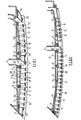
- FIG. 1 there is shown a section through part of a de-watering apparatus in accordance with the present invention.
- the drawing illustrates part of a housing 1 of an inverted suction box 5 and the cover 3 therefor.
- the suction box 5 is, in use, mounted above the travelling top forming wire of a paper forming machine (not indicated in the drawing).
- the suction box serves to remove water from a layer or web of fibrous suspension disposed between top and bottom forming wires.
- a plurality of foil strips 7 define an active surface which, in use is in contact with the top forming wire.
- the housing 1 of the suction box 5 has a base 9. to which mounting blocks 11 are secured. These mounting blocks serve to support plank members 13 which are releasably secured thereto by bolts 15. In the illustrated embodiment four plank members 13a, 13b, 13c and 13d are provided. Each plank member 13 carries a number of the foil strips,7 which are secured to the plank member 13 by way of a plurality of spaced apart pins 17.
- the foil strips 7 are elongate members which extend in a direction transverse to the direction of movement of the fibrous web through the machine:
- the pins 17 are disposed in parallel rows and project perpendicularly from the plane of the plank member to which they are connected. The pins in adjacent rows are preferably staggered in order to facilitate water flow.
- the left hand plank member 13 of Figure 1 carries four such rows of pins and each row carries a respective foil strip 7.
- the plank member second from left in Figure 1 carries four rows of pins and a foil strip 7 secured to each.
- Each foil strip 7 is secured to a row of pins by way of an elongated mounting bar 19 which supports the foils strip.
- the elongate mounting bar is fastened to the free end of each of the pins in the row.
- the elongate bar may be extruded T-section stainless steel.
- the pins are welded to the plank member.
- the construction using planks with a number of foils secured to each reduces the amount of machining.
- the mounting blocks 11 are machined at the appropriate angle required for each plank.
- the guides for receiving the foils are machined parallel to the plank mounting machine, thus further reducing the machining time.
- the foils may be machined flat, i.e. parallel to the plank mounting faces or to obtain higher accuracy of application half the foil may be machined at a small angle.
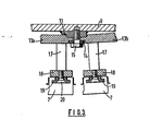
- FIG 3 shows a detail of a preferred mounting arrangement, from which it will be seen that the mounting block 11 is welded to the base of the suction box 9.
- the transverse edges of the plank members 13a, 13b are machined to compliment the machining on the mounting block 11 to arrive at the desired angle for the plank members 13a, 13b and hence the foils 7 carried thereby.
- Washers 14 and bolts 15 are employed to secure the plank members to the mounting blocks.
- the pins 17 carry at their free ends an elongate strip member 18 to which the mounting bar 19 is secured by set screws 20.
- plank member 13-disposed on the right of Figure 1 carries four rows of pins 17 but only two foil strips 7. These foil strips are wider than the strips shown on the left of the drawing and each of these wider strips is secured to the plank member by two rows of pins 17. As in the case of the plank members shown on the left, each row of pins carries an elongate mounting bar 19.
- the plank member second from the right carries two foil strips. One of these is supported on two rows of pins 17, in the same manner as illustrated for the right hand plank member, whilst the second of these strips 21 is secured to the plank member by way of a bracket 23.
- a leading foil strip 25 is carried by a.bracket 27, which is releasably secured to the suction box housing and a trailing foil strip is similarly carried by a bracket 29 which is releasably secured to the suction box housing.
- a bracket 27 which is releasably secured to the suction box housing
- a channel 31 is defined between the plank members 13a, 13b and the foil strips 7
- a channel 33 is defined between the plank members 13c, 13d and the foil strips 7.
- the foil strips 7 are spaced apart to define transversely directed slots 35 therebetween. Water passes through these slots and the channels 31,33 and is removed by way of respective passages 37 and 39.
- a weir 41 may be introduced between the channel 31 and the passage 37 and between the channel 33 and passage 39. Where a weir is incorporated, air pressure can be introduced through the cavity 45 formed between the bottom wall of the suction box housing and the plank members 13.
- the introduction of air serves to increase the water speed.
- Compressed air is fed at low pressure into the cavity 45 and distributed to the channel 31 by lines of drillings 46.
- lines of drillings 46 are arranged so that uniform air distribution is achieved.
- the weir 41 is preferably made adjustable and is positioned in such a way that only a thin layer of water flows above the foil mounting while air is filling the space above it. This prevents air from escaping.
- the thin high speed layer of water rushing over the foil mounting contributes to -â reduction in plugging by preventing the fibres from depositing over the box intervals.
- the width of the slots may be varied by changing the shape of the foil strips.
- the plank members are preferably mounted in a horizontal position.
- the adjacent rows of pins may be of different lengths in order to achieve the desired curvature of the active surface.
- the pins would be of the same length in order to standardise planks for interchangeability.
- each of the foil strips 7 is supported by a respective row of pins 17.
- the shape of the foils 7 is different in this embodiment.
- Four plank members 13 are shown to the left of the passage 37 and two to the left of the passage 39.
- the foils 7 may be either plastics or ceramic.
- the parts of Figure 1 are a plastics material such as HDP and the parts of Figure 2 are a ceramic material. '
- the embodiments described above have the advantages that there are no bridging pieces along the length of the slots 35 and the material on the sides of each slot can be kept to a minimum.
- the need for holding bolts in the slots is avoided.
- the T-bar mounting and pins can be easily electropolished individually and, when using ceramics, 'the foil surface can be glazed to promote cleanliness.
- Plastic foil strips can be machined on planers to a high surface finish on the side of the slots, whereas the present machining process by milling of slots in plastic covers.does not lend itself to good surface finish.
- planks carrying the foils enables plastics foils to be replaced with ceramic foils and vice-versa without changing the suction box design.
- the open area of the active surface can be changed easily by employing foils of different widths.
- part of the cover mounting can be changed without having to change the complete cover.
- the invention reduces the number of spaces required since only four strips and their mounting or only individual strips need to be kept on hand, instead of a complete cover.
- the invention enables the suction box to be designed and manufactured without compromising any future need for a different cover configuration. The amount of machining of the suction box is minimised.
- the use of individual foil strips considerably reduces the cost of ceramic and plastic covers.
Landscapes
- Paper (AREA)
- Nonwoven Fabrics (AREA)
Applications Claiming Priority (2)
| Application Number | Priority Date | Filing Date | Title |
|---|---|---|---|
| GB8225571 | 1982-09-08 | ||
| GB8225571 | 1982-09-08 |
Publications (3)
| Publication Number | Publication Date |
|---|---|
| EP0105636A2 true EP0105636A2 (fr) | 1984-04-18 |
| EP0105636A3 EP0105636A3 (en) | 1985-03-13 |
| EP0105636B1 EP0105636B1 (fr) | 1987-12-23 |
Family
ID=10532761
Family Applications (1)
| Application Number | Title | Priority Date | Filing Date |
|---|---|---|---|
| EP83305185A Expired EP0105636B1 (fr) | 1982-09-08 | 1983-09-07 | Perfectionnements pour appareils se rapportant à l'élimination de l'eau des suspensions de fibres |
Country Status (9)
| Country | Link |
|---|---|
| EP (1) | EP0105636B1 (fr) |
| JP (1) | JPS6030798B2 (fr) |
| AU (1) | AU559398B2 (fr) |
| BR (1) | BR8304830A (fr) |
| CA (1) | CA1226461A (fr) |
| DE (1) | DE3375031D1 (fr) |
| FI (1) | FI79728C (fr) |
| PL (1) | PL139933B1 (fr) |
| ZA (1) | ZA836581B (fr) |
Families Citing this family (1)
| Publication number | Priority date | Publication date | Assignee | Title |
|---|---|---|---|---|
| FI122245B (fi) * | 2009-03-18 | 2011-10-31 | Metso Paper Inc | Rainanmuodostuskoneen vedenpoistoelin |
Family Cites Families (1)
| Publication number | Priority date | Publication date | Assignee | Title |
|---|---|---|---|---|
| DE2253095A1 (de) * | 1972-10-26 | 1974-05-09 | Kimberly Clark Co | Saugkasten zur entwaesserung eines filzbandes in papiermaschinen |
-
1983
- 1983-08-30 CA CA000435673A patent/CA1226461A/fr not_active Expired
- 1983-09-02 FI FI833136A patent/FI79728C/fi not_active IP Right Cessation
- 1983-09-05 BR BR8304830A patent/BR8304830A/pt not_active IP Right Cessation
- 1983-09-05 ZA ZA836581A patent/ZA836581B/xx unknown
- 1983-09-05 AU AU18690/83A patent/AU559398B2/en not_active Ceased
- 1983-09-07 EP EP83305185A patent/EP0105636B1/fr not_active Expired
- 1983-09-07 DE DE8383305185T patent/DE3375031D1/de not_active Expired
- 1983-09-08 PL PL1983243686A patent/PL139933B1/pl unknown
- 1983-09-08 JP JP58164278A patent/JPS6030798B2/ja not_active Expired
Also Published As
| Publication number | Publication date |
|---|---|
| FI79728B (fi) | 1989-10-31 |
| AU559398B2 (en) | 1987-03-12 |
| BR8304830A (pt) | 1984-04-24 |
| JPS6030798B2 (ja) | 1985-07-18 |
| EP0105636B1 (fr) | 1987-12-23 |
| ZA836581B (en) | 1984-07-25 |
| EP0105636A3 (en) | 1985-03-13 |
| JPS59116493A (ja) | 1984-07-05 |
| FI833136A0 (fi) | 1983-09-02 |
| PL139933B1 (en) | 1987-03-31 |
| FI833136L (fi) | 1984-03-09 |
| CA1226461A (fr) | 1987-09-08 |
| AU1869083A (en) | 1984-03-15 |
| DE3375031D1 (en) | 1988-02-04 |
| FI79728C (fi) | 1990-02-12 |
| PL243686A1 (en) | 1984-06-18 |
Similar Documents
| Publication | Publication Date | Title |
|---|---|---|
| US4544449A (en) | Apparatus for de-watering fibrous suspensions | |
| US4909906A (en) | Cover piece for a suction box with wavelike or zigzag passage | |
| US5089090A (en) | Continuous controlled drainage | |
| US5320713A (en) | Method of using a forming section of a papermaking machine | |
| US3393124A (en) | Elongated supporting elements for the fourdrinier wire of a papermaking machine | |
| CA2057879C (fr) | Bloc de mise en forme a reglage de pression | |
| EP0062983B1 (fr) | Régle de support pour la section toile de fabrication d'une machine à papier | |
| USRE40720E1 (en) | Fabric support element for a papermaking machine | |
| EP0105636B1 (fr) | Perfectionnements pour appareils se rapportant à l'élimination de l'eau des suspensions de fibres | |
| US4089739A (en) | Head box having guide block and adjustable slice plates | |
| KR20000015915A (ko) | 블로워 노즐 | |
| CA2215482A1 (fr) | Caisse aspirante avec dispositifs de blocage lateraux | |
| CN1751154B (zh) | 造纸机的成形网支承元件 | |
| CN1886555B (zh) | 用于造纸机的混合型成形部 | |
| FI63077B (fi) | Foerfarande och anordning foer reglering av profilen av en fiberbana i en pappersmaskin | |
| FI109814B (fi) | Laitteisto paperi- tai kartonkirainan muodostamiseksi | |
| US3265560A (en) | Suction box cover for a papermaking machine | |
| CN1886554B (zh) | 用于双织物造纸机的隙式成形部 | |
| EP0850334B1 (fr) | Element de lame resistant a l'usure | |
| KR100824681B1 (ko) | 제지기용의 갭(gap) 타입 2-직물 성형부 | |
| RU2334035C2 (ru) | Формующая часть с зазорами, предназначенная для двухсеточной бумагоделательной машины | |
| FI64673C (fi) | Etageinloppslaoda foer pappersmaskin | |
| AU633105B2 (en) | Continuous controlled drainage | |
| JP3403025B2 (ja) | 抄紙機用カウンタブレード | |
| SU1278374A1 (ru) | Напорный щик бумагоделательной машины |
Legal Events
| Date | Code | Title | Description |
|---|---|---|---|
| PUAI | Public reference made under article 153(3) epc to a published international application that has entered the european phase |
Free format text: ORIGINAL CODE: 0009012 |
|
| AK | Designated contracting states |
Designated state(s): DE FR GB SE |
|
| PUAL | Search report despatched |
Free format text: ORIGINAL CODE: 0009013 |
|
| AK | Designated contracting states |
Designated state(s): DE FR GB SE |
|
| 17P | Request for examination filed |
Effective date: 19850424 |
|
| 17Q | First examination report despatched |
Effective date: 19860325 |
|
| GRAA | (expected) grant |
Free format text: ORIGINAL CODE: 0009210 |
|
| AK | Designated contracting states |
Kind code of ref document: B1 Designated state(s): DE FR GB SE |
|
| REF | Corresponds to: |
Ref document number: 3375031 Country of ref document: DE Date of ref document: 19880204 |
|
| ET | Fr: translation filed | ||
| PLBE | No opposition filed within time limit |
Free format text: ORIGINAL CODE: 0009261 |
|
| STAA | Information on the status of an ep patent application or granted ep patent |
Free format text: STATUS: NO OPPOSITION FILED WITHIN TIME LIMIT |
|
| 26N | No opposition filed | ||
| EAL | Se: european patent in force in sweden |
Ref document number: 83305185.7 |
|
| PGFP | Annual fee paid to national office [announced via postgrant information from national office to epo] |
Ref country code: GB Payment date: 19980814 Year of fee payment: 16 |
|
| PGFP | Annual fee paid to national office [announced via postgrant information from national office to epo] |
Ref country code: FR Payment date: 19980821 Year of fee payment: 16 Ref country code: DE Payment date: 19980821 Year of fee payment: 16 |
|
| PGFP | Annual fee paid to national office [announced via postgrant information from national office to epo] |
Ref country code: SE Payment date: 19980824 Year of fee payment: 16 |
|
| PG25 | Lapsed in a contracting state [announced via postgrant information from national office to epo] |
Ref country code: GB Free format text: LAPSE BECAUSE OF NON-PAYMENT OF DUE FEES Effective date: 19990907 |
|
| PG25 | Lapsed in a contracting state [announced via postgrant information from national office to epo] |
Ref country code: SE Free format text: THE PATENT HAS BEEN ANNULLED BY A DECISION OF A NATIONAL AUTHORITY Effective date: 19990929 |
|
| GBPC | Gb: european patent ceased through non-payment of renewal fee |
Effective date: 19990907 |
|
| EUG | Se: european patent has lapsed |
Ref document number: 83305185.7 |
|
| PG25 | Lapsed in a contracting state [announced via postgrant information from national office to epo] |
Ref country code: FR Free format text: LAPSE BECAUSE OF NON-PAYMENT OF DUE FEES Effective date: 20000531 |
|
| PG25 | Lapsed in a contracting state [announced via postgrant information from national office to epo] |
Ref country code: DE Free format text: LAPSE BECAUSE OF NON-PAYMENT OF DUE FEES Effective date: 20000701 |
|
| REG | Reference to a national code |
Ref country code: FR Ref legal event code: ST |