EP0105700A2 - Méthodes d'analyse utilisant la résonance magnétique nucléaire - Google Patents
Méthodes d'analyse utilisant la résonance magnétique nucléaire Download PDFInfo
- Publication number
- EP0105700A2 EP0105700A2 EP83305804A EP83305804A EP0105700A2 EP 0105700 A2 EP0105700 A2 EP 0105700A2 EP 83305804 A EP83305804 A EP 83305804A EP 83305804 A EP83305804 A EP 83305804A EP 0105700 A2 EP0105700 A2 EP 0105700A2
- Authority
- EP
- European Patent Office
- Prior art keywords
- gradients
- slice
- pulse
- spin
- reversal
- Prior art date
- Legal status (The legal status is an assumption and is not a legal conclusion. Google has not performed a legal analysis and makes no representation as to the accuracy of the status listed.)
- Granted
Links
Images


Classifications
-
- G—PHYSICS
- G01—MEASURING; TESTING
- G01R—MEASURING ELECTRIC VARIABLES; MEASURING MAGNETIC VARIABLES
- G01R33/00—Arrangements or instruments for measuring magnetic variables
- G01R33/20—Arrangements or instruments for measuring magnetic variables involving magnetic resonance
- G01R33/44—Arrangements or instruments for measuring magnetic variables involving magnetic resonance using nuclear magnetic resonance [NMR]
- G01R33/48—NMR imaging systems
- G01R33/483—NMR imaging systems with selection of signals or spectra from particular regions of the volume, e.g. in vivo spectroscopy
- G01R33/485—NMR imaging systems with selection of signals or spectra from particular regions of the volume, e.g. in vivo spectroscopy based on chemical shift information [CSI] or spectroscopic imaging, e.g. to acquire the spatial distributions of metabolites
-
- G—PHYSICS
- G01—MEASURING; TESTING
- G01R—MEASURING ELECTRIC VARIABLES; MEASURING MAGNETIC VARIABLES
- G01R33/00—Arrangements or instruments for measuring magnetic variables
- G01R33/20—Arrangements or instruments for measuring magnetic variables involving magnetic resonance
- G01R33/44—Arrangements or instruments for measuring magnetic variables involving magnetic resonance using nuclear magnetic resonance [NMR]
- G01R33/48—NMR imaging systems
- G01R33/54—Signal processing systems, e.g. using pulse sequences ; Generation or control of pulse sequences; Operator console
- G01R33/56—Image enhancement or correction, e.g. subtraction or averaging techniques, e.g. improvement of signal-to-noise ratio and resolution
- G01R33/561—Image enhancement or correction, e.g. subtraction or averaging techniques, e.g. improvement of signal-to-noise ratio and resolution by reduction of the scanning time, i.e. fast acquiring systems, e.g. using echo-planar pulse sequences
- G01R33/5615—Echo train techniques involving acquiring plural, differently encoded, echo signals after one RF excitation, e.g. using gradient refocusing in echo planar imaging [EPI], RF refocusing in rapid acquisition with relaxation enhancement [RARE] or using both RF and gradient refocusing in gradient and spin echo imaging [GRASE]
- G01R33/5616—Echo train techniques involving acquiring plural, differently encoded, echo signals after one RF excitation, e.g. using gradient refocusing in echo planar imaging [EPI], RF refocusing in rapid acquisition with relaxation enhancement [RARE] or using both RF and gradient refocusing in gradient and spin echo imaging [GRASE] using gradient refocusing, e.g. EPI
Definitions
- This invention relates to methods of investigating a body by nuclear magnetic resonance (NMR).
- a further NMR parameter in which interest has grown rapidly over recent years is chemical shift.
- it is, in principle, possible to obtain sufficient information to construct a two dimensional chemical shift map, with corresponding image of the object.
- this process may be somewhat lengthy and tedious.
- EP echo planar
- a method of investigating a body by NMR comprises: preferentially exciting resonance in a slice of the body; applying a magnetic field to said body having first and second gradients in different directions in said slice, both said gradients being periodically reversed at regular intervals; detecting the free induction decay signals occurring when said gradients are applied; and processing the detected signals to retrieve data.
- the invention further provides a method of investigating a body by NMR comprising performing the method according to the invention twice with at least one of the gradients starting in the second performance with opposite polarity with respect to the first performance.
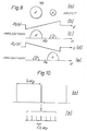
- FIG. 1 consider an extended body 1 placed in a polarizing magnetic field B 0 and a magnetic field gradient G z .
- a tailored selective RF pulse B 1 (t) applied along the x-axis in the rotating reference frame so as to excite preferentially those spins which lie in a slice 3 of the body (shaded) of thickness ⁇ z at displacement z.
- the corresponding range of Larmor frequencies excited is given approximately by whereAis the magneto-gyric ratio of the particular spin species considered. It is approximate in the sense that such tailored pulses automatically introduce some dispersive element of magnetization.
- the unwanted x-component of signal may be minimized by subtle changes in the RF pulse shape. Since selection does not unduly perturb adjacent layers of material, rapid scanning of several layers may be achieved without the necessity of waiting T 1 , the spin lattice relaxation time, between different plane scans.
- One dimensional mapping of the data contained in the signal of Figure 2c may be achieved by a conventional EP imaging procedure as illustrated in Figure 3.
- FIGS 3a and 3b show the slice selection procedure described above with reference to Figure 2 together with an additional y-gradient (G ) modulation (Figure 3c), commenced at the focussed signal peak, the x-directional gradient (G ) being zero and therefore not shown.
- G y is trapezoidally modulated (ideally rectangular) and in a perfectly homogeneous static magnetic field B 0 produces an initial FID followed by a sequence of modified spin echoes 2n ⁇ y ⁇ T 2 where T 2 is the spin-spin relaxation time. This part of the procedure is identical to a standard alignment procedure in EP imaging.
- the selected slice of material, Figure 4a is a homogeneous disc.
- the spin projection of this disc in a static gradient G y gives a semi-elliptic absorption line shape g( ⁇ )(dotted Figure 4b). This is obtained by sampling just the initial FID.
- the effect of sampling the complete spin echo sequence of Figure 3d and Fourier transforming is to convert the continuous projection profile (dotted) into the discrete stick spectrum, Figure 4b.
- the stick spacing ⁇ y is related to the spin echo period 2 ⁇ and the number of data sample points P with sampling time ⁇ o by the following relationships where ⁇ p is the angular frequency per point in the Fourier transform (FT) and
- the process of converting the continuous projection profile into a stick spectrum effectively squeezes signals obtained from the continuous spectrum in the range ⁇ y (that is to say, the area under the profile) into a single frequency stick, with equal area and centred within the frequency element.
- the tubes are separated along the y-axis and therefore the chemical shift map and its projection spectrum can be unambiguously assigned. That is to say, the signal from tube A can be unambiguously assigned to the absorption peak ⁇ A , Figure 5c,via the y-5 plot of Figure 5b.
- the encoding is achieved entirely by G y and by appropriately placing the tubes with y displacements so that no overlap occurs.
- Figure 9a shows the specimen projection spectra in both +G y (solid) and -G y (dotted).
- the separated y- ⁇ maps are shown in Figure 9c and are assignable.
- the map obtained without performing the double shot experiment and subsequent editing and splicing procedure discussed above leads to a y- ⁇ map which overlaps along the y-axis (see Figure 9d) through two causes.
- the first is an aliasing like effect when one or more of the specimens fills more than half the object field along the y direction.
- the G y phase alternated sequence described above is really a two shot experiment with T n between shots. This is a perfectly satisfactory method of chemical shift mapping when time is not of primary concern. However, if a complete one shot experiment is necessary, it is straightforward to combine the two phases of the experiment into a single experiment in which T D is effectively zero between phase alternated pairs. In this case the first and second selective RF pulses must have nutation or flip angles of 45° and 90 0 respectively. Other combinations of lower flip angle are also possible.
- Encoding along the x-axis is achieved by applying an additional G gradient as well as the. G gradient already described.
- the process is similar to EP imaging and for proper interpretation of the shift spectra corresponding spin density images are required. However, as explained later, full spin information including the spin density images are automatically available by the method described.
- Initial excitation of the spin system may be by using a non-selective pulse to excite all spins within the transmitter coil volume.
- a non-selective pulse to excite all spins within the transmitter coil volume.
- p(x,y,z) is the spin density
- ⁇ the magneto-gyric ratio, here considered the same for all spins
- G x (t'), G y (t') and G z (t') are linear time dependent field gradients.
- the time dependence for chemical shift mapping is preferably trapezoidal, although other time dependencies can be accommodated with appropriate non-linear transformation or non-linear sampling and FT with appropriate correction for the non-linearities introduced by sampling.
- Equation (6) can be reduced to where we assume that the initial excitation RF pulse is selective to a plane z.
- the spin density over a selected slice does not change significantly over the slice thickness and may therefore be replaced by an average spin density over z given by where ⁇ Z (x,y) is the average over the slice thickness ⁇ z. This will be true for thin slices.
- ⁇ Z (x,y) is the average over the slice thickness ⁇ z.
- TMR static magnetic field shaping
- a zoom facility could be constructed to look in finer detail at a single organ like the heart or a kidney without the need to examine the whole body cross- section. This facility would be of value in straightforward NMR imaging as well as in mapping of other NMR parameters, such as ⁇ , flow, T 1 , T 2 , etc.
- Equation (9) may be written as where If G y (t') is periodic modulo 4 ⁇ y then Equation (11) may be written as two expressions f,(x,t) and f 2 (x,t) depending on the starting phase of G (0).
- Equation (12a) Fourier transformation of Equation (12a) gives for large N where ⁇ ( ⁇ y - mA ⁇ y ) is the Dirac delta function and denotes convolution with the Fourier transform of the editing function E( ⁇ y ), etc.
- Equation (13) The element ⁇ y is the spatial displacement of the sticks in the spectrum of Equation (13).
- Equations (12a and b) can give a related time function which represents evolution of the spin system in either a wholly positive gradient +Gy (t) or a wholly negative gradient -G y (t).
- the two re3ated functions are and
- Equation (16) describes an FID type signal when G y is time independent.
- Equation (20) describes an FID type signal when G y is time independent.
- G x (t') is periodic modulo 4 ⁇ x '
- h 1 (m ⁇ y,t) and h 2 (m ⁇ y,t) which describe periodic spin echo sequences in which the initial phase of G x (t) is positive and negative respectively.
- h 1 and h 2 may be spliced to give h + (m ⁇ y, t) and h - (m ⁇ y,t) where where k - describes signal evolution in +ve or -ve x-gradients only.
- Equation (22) The function h - gives on Fourier transformation H - . which is similar to Equation (22).
- Equation (22) gives h + which when substituted for h(mAy,t) in Equation (19b) gives the fully spliced or edited function where the pixel volume ⁇ v is
- Equation (24) is one of four spliced functions, i.e. S ++ , S +- , S -+ , and S -- , which may be produced.
- Each function contains all the spatial information or spin density and by a suitable data reordering process in the frequency domain, these functions may be coadded to improve signal/noise.
- S ++ spliced functions
- T S is the time the experiment lasts and corresponds to the echo train length and total sampling time of the echo sequence.
- Equation (31d) applies for a real point FT (2N ⁇ N).
- ⁇ (x,y) is a continuous function of the position coordinates, it is convenient to break down the integral to a discrete sum of common chemical shifts, localized at specific parts of the object.
- the total chemically shifted distribution may be represented as weighted sum of shift components, i.e.
- a ,m component introduces a common frequency shift ⁇ j for all regions containing that shift.
- the actual positions of the shifted regions are mapped by the gradients together with the density function (Z).
- Equation (34) we also see from Equation (34) that for full unambiguous assignment of (no overlap or wraparound) we require and where L and N are as defined previously.
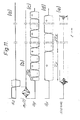
- Figures 11d and 11c respectively show the modulation diagrams for G x and G y which may be used in practice. Experimental difficulty will arise due to G switching at an echo peak, but since the signal is likely to be quite small here anyway, editing these echoes may not be too troublesome.
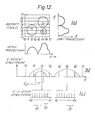
- Figure 12a shows the two dimensional object field of Figure 12a. This contains three discs of homogeneously distributed material and having two chemical shifts ⁇ 1 and ⁇ 2 as shown.
- the stick spectrum profiles are semi-elliptical in all cases, since the objects are homogeneous discs. If now the G modulation is added, we obtain a splitting of each y stick into a multiplet as shown for two cases y 2 and y 5 in Figure 12c.
- Figure 12c The spectrum of Figure 12c is in a form which is readily interpretable by stacking the 16 point data sets in the form of a third angle projection. This is illustrated in Figure 13afor the object of Figure 12a.
- Figure 13a For example projection along the ⁇ axis gives the spin density map Figure 13b.
- Projection along the x-axis gives the y - ⁇ density plot, Figure 13c, which is the result obtained in Section 2 without G x .
- projection along the y-axis gives the x - ⁇ density plot, Figure 13a.
Landscapes
- Physics & Mathematics (AREA)
- General Physics & Mathematics (AREA)
- High Energy & Nuclear Physics (AREA)
- Condensed Matter Physics & Semiconductors (AREA)
- Spectroscopy & Molecular Physics (AREA)
- Nuclear Medicine, Radiotherapy & Molecular Imaging (AREA)
- Radiology & Medical Imaging (AREA)
- Engineering & Computer Science (AREA)
- Signal Processing (AREA)
- General Health & Medical Sciences (AREA)
- Health & Medical Sciences (AREA)
- Optics & Photonics (AREA)
- Magnetic Resonance Imaging Apparatus (AREA)
Applications Claiming Priority (2)
| Application Number | Priority Date | Filing Date | Title |
|---|---|---|---|
| GB8228567 | 1982-10-06 | ||
| GB8228567 | 1982-10-06 |
Publications (3)
| Publication Number | Publication Date |
|---|---|
| EP0105700A2 true EP0105700A2 (fr) | 1984-04-18 |
| EP0105700A3 EP0105700A3 (en) | 1985-05-02 |
| EP0105700B1 EP0105700B1 (fr) | 1989-01-04 |
Family
ID=10533428
Family Applications (1)
| Application Number | Title | Priority Date | Filing Date |
|---|---|---|---|
| EP83305804A Expired EP0105700B1 (fr) | 1982-10-06 | 1983-09-28 | Méthodes d'analyse utilisant la résonance magnétique nucléaire |
Country Status (5)
| Country | Link |
|---|---|
| US (1) | US4588948A (fr) |
| EP (1) | EP0105700B1 (fr) |
| JP (1) | JPS5990552A (fr) |
| DE (1) | DE3378848D1 (fr) |
| GB (1) | GB2128339B (fr) |
Cited By (2)
| Publication number | Priority date | Publication date | Assignee | Title |
|---|---|---|---|---|
| EP0165610A3 (en) * | 1984-06-20 | 1986-10-01 | Hitachi, Ltd. | High speed imaging method with three-dimensional nmr |
| EP0240319A3 (en) * | 1986-03-31 | 1989-08-30 | Kabushiki Kaisha Toshiba | Magnetic resonance imaging system |
Families Citing this family (23)
| Publication number | Priority date | Publication date | Assignee | Title |
|---|---|---|---|---|
| US4689562A (en) * | 1983-10-11 | 1987-08-25 | Elscint Ltd. | NMR Imaging method and system |
| GB8415078D0 (en) * | 1984-06-13 | 1984-07-18 | Picker Int Ltd | Nuclear magnetic resonance imaging |
| JPH0811112B2 (ja) * | 1985-03-11 | 1996-02-07 | 株式会社日立製作所 | 核磁気共鳴を用いた検査装置 |
| JPH0714386B2 (ja) * | 1985-04-10 | 1995-02-22 | 株式会社日立製作所 | 核磁気共鳴を用いた検査装置 |
| US4678996A (en) * | 1985-05-07 | 1987-07-07 | Picker International, Inc. | Magnetic resonance imaging method |
| JPS61272644A (ja) * | 1985-05-29 | 1986-12-02 | Yokogawa Electric Corp | 核磁気共鳴撮像装置 |
| JPS6250649A (ja) * | 1985-08-30 | 1987-03-05 | Mitsubishi Electric Corp | 核磁気共鳴映像法 |
| JPS62148658A (ja) * | 1985-12-23 | 1987-07-02 | 株式会社日立製作所 | 核磁気共鳴を用いた検査方法 |
| JPS62231639A (ja) * | 1986-03-31 | 1987-10-12 | 工業技術院長 | 3次元物質構造解析表示方法 |
| US5168228A (en) * | 1987-05-14 | 1992-12-01 | National Researh Development Corporation | Echo planar imaging systems |
| JP2594953B2 (ja) * | 1987-07-08 | 1997-03-26 | 株式会社日立製作所 | 核磁気共鳴を用いた検査装置 |
| GB8719244D0 (en) * | 1987-08-14 | 1987-09-23 | Mansfield P | Nmr imaging |
| JPH021235A (ja) * | 1987-11-06 | 1990-01-05 | Hitachi Ltd | 磁気共鳴イメージング装置の画像再構成方式 |
| US4901021A (en) * | 1987-11-06 | 1990-02-13 | Hitachi, Ltd. | Image constructing device included in a magnetic resonance imaging apparatus |
| GB8909270D0 (en) * | 1989-04-24 | 1989-06-07 | Hafslund Nycomed Innovation | Method |
| US5086275A (en) * | 1990-08-20 | 1992-02-04 | General Electric Company | Time domain filtering for nmr phased array imaging |
| US5151656A (en) * | 1990-12-11 | 1992-09-29 | General Electric Company | Correction of nmr data acquired by an echo-planar technique |
| JP3386864B2 (ja) * | 1993-10-28 | 2003-03-17 | 株式会社日立メディコ | 核磁気共鳴撮影方法及び装置 |
| JP3369688B2 (ja) * | 1993-12-27 | 2003-01-20 | 株式会社日立製作所 | 核磁気共鳴を用いた検査装置 |
| US5652516A (en) * | 1996-01-22 | 1997-07-29 | The Board Of Trustees Of The Leland Stanford Junior University | Spectroscopic magnetic resonance imaging using spiral trajectories |
| US6285187B1 (en) | 1999-04-28 | 2001-09-04 | General Electric Company | Method and apparatus for reducing artifacts in echo planar imaging |
| US6259250B1 (en) * | 1999-04-28 | 2001-07-10 | General Electric Company | Method and apparatus for reducing artifacts in echo planar imaging |
| WO2010116782A1 (fr) | 2009-03-30 | 2010-10-14 | 株式会社 日立製作所 | Dispositif de résonance magnétique |
Family Cites Families (14)
| Publication number | Priority date | Publication date | Assignee | Title |
|---|---|---|---|---|
| US4021726A (en) * | 1974-09-11 | 1977-05-03 | National Research Development Corporation | Image formation using nuclear magnetic resonance |
| GB1580787A (en) * | 1976-04-14 | 1980-12-03 | Mansfield P | Nuclear magnetic resonance apparatus and methods |
| GB1596160A (en) * | 1976-12-15 | 1981-08-19 | Nat Res Dev | Nuclear magnetic resonance apparatus and methods |
| GB1601970A (en) * | 1978-05-31 | 1981-11-04 | Nat Res Dev | Methods of deriving image information from objects |
| US4318043A (en) * | 1978-07-20 | 1982-03-02 | The Regents Of The University Of California | Method and apparatus for rapid NMR imaging of nuclear densities within an object |
| DE2920549A1 (de) * | 1979-05-21 | 1980-12-04 | Siemens Ag | Verfahren und vorrichtung zur magnetfeldmessung |
| US4339716A (en) * | 1979-05-23 | 1982-07-13 | Picker International Limited | Nuclear magnetic resonance systems |
| GB2057142B (en) * | 1979-08-10 | 1983-09-14 | Emi Ltd | Nuclear magnetic resonance systems |
| US4361807A (en) * | 1979-08-10 | 1982-11-30 | Picker International Limited | Nuclear magnetic resonance systems |
| US4307343A (en) * | 1979-08-20 | 1981-12-22 | General Electric Company | Moving gradient zeugmatography |
| GB2079463B (en) * | 1980-03-14 | 1984-10-10 | Nat Res Dev | Nmr imaging method |
| GB2107469B (en) * | 1981-09-21 | 1985-09-18 | Peter Mansfield | Nuclear magnetic resonance methods |
| US4607223A (en) * | 1982-08-13 | 1986-08-19 | National Research Development Corporation | Nuclear magnetic resonance imaging method |
| NL8203519A (nl) * | 1982-09-10 | 1984-04-02 | Philips Nv | Werkwijze en inrichting voor het bepalen van een kernmagnetisatieverdeling in een deel van een lichaam. |
-
1983
- 1983-09-28 DE DE8383305804T patent/DE3378848D1/de not_active Expired
- 1983-09-28 EP EP83305804A patent/EP0105700B1/fr not_active Expired
- 1983-09-28 GB GB08325918A patent/GB2128339B/en not_active Expired
- 1983-10-04 US US06/538,977 patent/US4588948A/en not_active Expired - Lifetime
- 1983-10-06 JP JP58187673A patent/JPS5990552A/ja active Granted
Cited By (2)
| Publication number | Priority date | Publication date | Assignee | Title |
|---|---|---|---|---|
| EP0165610A3 (en) * | 1984-06-20 | 1986-10-01 | Hitachi, Ltd. | High speed imaging method with three-dimensional nmr |
| EP0240319A3 (en) * | 1986-03-31 | 1989-08-30 | Kabushiki Kaisha Toshiba | Magnetic resonance imaging system |
Also Published As
| Publication number | Publication date |
|---|---|
| JPH0350534B2 (fr) | 1991-08-02 |
| US4588948A (en) | 1986-05-13 |
| GB8325918D0 (en) | 1983-11-02 |
| EP0105700A3 (en) | 1985-05-02 |
| DE3378848D1 (en) | 1989-02-09 |
| EP0105700B1 (fr) | 1989-01-04 |
| JPS5990552A (ja) | 1984-05-25 |
| GB2128339B (en) | 1986-09-17 |
| GB2128339A (en) | 1984-04-26 |
Similar Documents
| Publication | Publication Date | Title |
|---|---|---|
| EP0105700B1 (fr) | Méthodes d'analyse utilisant la résonance magnétique nucléaire | |
| CA1147807A (fr) | Methodes de generation de donnees d'images a partir des objets a representer | |
| EP0086972B2 (fr) | Méthode de formation d'images à RMN surmontant les effets T2* dans un champ magnétique statique non-homogène | |
| US4607223A (en) | Nuclear magnetic resonance imaging method | |
| JP2000135206A5 (ja) | 4重フィールドエコーシーケンスを用いて水と脂肪を定量的にmr撮影する装置 | |
| EP0098426A2 (fr) | Procédé pour l'élimination des effets de faux signaux à décroissance d'induction libre de résonance magnétique nucléaire causés par des impulsions imparfaites de fréquence radio à 180 degrés | |
| US5652516A (en) | Spectroscopic magnetic resonance imaging using spiral trajectories | |
| EP0349976A2 (fr) | Méthode de reconstruction d'image en imagerie par RMN | |
| KR850002323A (ko) | 핵자기 공명데이타 발생방법 | |
| EP0222325A2 (fr) | Méthode par laquelle on annule les moments du gradient de champ magnétique pour réduire dans une image RMN, les parasites occasionnés par les noyaux en déplacement | |
| US5064638A (en) | Simultaneous multinuclear magnetic resonance imaging and spectroscopy | |
| JPH0287050A (ja) | 結合スピンを含む新陳代謝物質によるnmr信号の二次元スペクトルを作る方法と装置 | |
| US4682110A (en) | Method of reducing artefacts in images formed by means of fourier zeugmatography | |
| JPH07265281A (ja) | Mrイメージング装置 | |
| Zhou et al. | High‐field MR microscopy using fast spin‐echoes | |
| US5241271A (en) | Ultra-fast imaging method and apparatus | |
| US4318044A (en) | Methods of indicating nuclear spin density distribution | |
| JPH01502323A (ja) | 核磁気共鳴の画像化のための方法及び装置 | |
| US4714884A (en) | Method of eliminating effects of spurious NMR signals caused by imperfect 180 degree RF pulses | |
| US4706023A (en) | Method of reducing artefacts in images formed by means of Fourier zeugmatography | |
| EP0541636B1 (fr) | Ameliorations concernant la spectroscopie et l'imagerie par resonance magnetique | |
| EP0182873A1 (fr) | Prise d'image de fourier nmr a partir d'echos multiples | |
| Cho et al. | Multipoint K‐space point mapping (KPM) technique for NMR microscopy | |
| Mansfield | Nuclear magnetic resonance imaging | |
| Loecher et al. | k-Space |
Legal Events
| Date | Code | Title | Description |
|---|---|---|---|
| PUAI | Public reference made under article 153(3) epc to a published international application that has entered the european phase |
Free format text: ORIGINAL CODE: 0009012 |
|
| AK | Designated contracting states |
Designated state(s): DE FR NL |
|
| PUAL | Search report despatched |
Free format text: ORIGINAL CODE: 0009013 |
|
| AK | Designated contracting states |
Designated state(s): DE FR NL |
|
| 17P | Request for examination filed |
Effective date: 19851010 |
|
| 17Q | First examination report despatched |
Effective date: 19870303 |
|
| GRAA | (expected) grant |
Free format text: ORIGINAL CODE: 0009210 |
|
| RAP3 | Party data changed (applicant data changed or rights of an application transferred) |
Owner name: MANSFIELD, PETER |
|
| AK | Designated contracting states |
Kind code of ref document: B1 Designated state(s): DE FR NL |
|
| REF | Corresponds to: |
Ref document number: 3378848 Country of ref document: DE Date of ref document: 19890209 |
|
| ET | Fr: translation filed | ||
| PLBE | No opposition filed within time limit |
Free format text: ORIGINAL CODE: 0009261 |
|
| STAA | Information on the status of an ep patent application or granted ep patent |
Free format text: STATUS: NO OPPOSITION FILED WITHIN TIME LIMIT |
|
| 26N | No opposition filed | ||
| PGFP | Annual fee paid to national office [announced via postgrant information from national office to epo] |
Ref country code: DE Payment date: 19981005 Year of fee payment: 16 |
|
| PG25 | Lapsed in a contracting state [announced via postgrant information from national office to epo] |
Ref country code: DE Free format text: LAPSE BECAUSE OF NON-PAYMENT OF DUE FEES Effective date: 20000701 |
|
| PGFP | Annual fee paid to national office [announced via postgrant information from national office to epo] |
Ref country code: NL Payment date: 20010927 Year of fee payment: 19 |
|
| PGFP | Annual fee paid to national office [announced via postgrant information from national office to epo] |
Ref country code: FR Payment date: 20020903 Year of fee payment: 20 |
|
| PG25 | Lapsed in a contracting state [announced via postgrant information from national office to epo] |
Ref country code: NL Free format text: LAPSE BECAUSE OF NON-PAYMENT OF DUE FEES Effective date: 20030401 |