EP0105769A2 - Sicherheitsverfahren und Sicherheitsvorrichtung für Hängebahnförderanlage mit Kettenantrieb - Google Patents
Sicherheitsverfahren und Sicherheitsvorrichtung für Hängebahnförderanlage mit Kettenantrieb Download PDFInfo
- Publication number
- EP0105769A2 EP0105769A2 EP83401726A EP83401726A EP0105769A2 EP 0105769 A2 EP0105769 A2 EP 0105769A2 EP 83401726 A EP83401726 A EP 83401726A EP 83401726 A EP83401726 A EP 83401726A EP 0105769 A2 EP0105769 A2 EP 0105769A2
- Authority
- EP
- European Patent Office
- Prior art keywords
- chain
- drive
- safety chain
- circuit
- safety
- Prior art date
- Legal status (The legal status is an assumption and is not a legal conclusion. Google has not performed a legal analysis and makes no representation as to the accuracy of the status listed.)
- Withdrawn
Links
Images



Classifications
-
- B—PERFORMING OPERATIONS; TRANSPORTING
- B65—CONVEYING; PACKING; STORING; HANDLING THIN OR FILAMENTARY MATERIAL
- B65G—TRANSPORT OR STORAGE DEVICES, e.g. CONVEYORS FOR LOADING OR TIPPING, SHOP CONVEYOR SYSTEMS OR PNEUMATIC TUBE CONVEYORS
- B65G43/00—Control devices, e.g. for safety, warning or fault-correcting
- B65G43/06—Control devices, e.g. for safety, warning or fault-correcting interrupting the drive in case of driving element breakage; Braking or stopping loose load-carriers
Definitions
- the present invention essentially relates to a safety method and device for triggering the emergency stop of loads, such as vehicle bodies, conveyed by an overhead conveyor with drive chain.
- a first circuit comprises carriages which support loads, suspended from a rail guiding the movements of the carriages.
- a second circuit arranged above the first, comprises a rail on which flow trolleys carrying a drive chain. Certain links in this chain are fitted with articulated drive fingers or pusher cleats which can come into engagement with the carriages of the first circuit and then ensure the transmission of the drive movement from the chain to the loads.
- the present invention therefore aims to solve the aforementioned drawbacks by providing a solution for triggering the emergency stop of the loads conveyed by an overhead conveyor with drive chain, or more precisely carts supporting the loads, which is all - perfectly safe and particularly simple in design.
- This solution consists, according to the present invention, in a method of triggering the emergency stop in an overhead conveyor of loads with a drive chain, characterized in that an auxiliary circuit provided with a safety chain is provided. , placed at least in high-risk places in the event of a break in the drive, such as downhill, this safety chain being driven by the drive chain and comprising lugs each of which is placed in front of a load on its path, variations in the tension of the safety chain are detected and the safety chain is stopped when these variations in tension cross a tolerated threshold to which corresponds the stop of a load on the cleat which precedes it as a result of a breakdown in the overhead conveyor drive system.
- the drive of the drive chain is also stopped simultaneously.
- the safety chain is stopped by triggering a system for braking the rotation of one of said return sprockets.
- the present invention also relates to a device for triggering the emergency stop of loads, such as vehicle bodies, conveyed by an overhead conveyor with drive chain, characterized in that it comprises a auxiliary circuit provided with a safety chain, arranged at least in high-risk places such as downhill, and driven by said drive chain; said safety chain comprising lugs each of which is placed in front of one of said loads on its path; means for defecting variations in tension of the safety chain and means for triggering the stopping of the safety chain when the variations in tension cross a tolerated threshold to which corresponds the stop of a load on the cleat which precedes it due to a break in the overhead conveyor drive system.
- an accident on the drive system can no longer cause a sudden drop in loads along the descents, and this avoids any risk of personal injury at the same time as damage to the loads .
- FIG 1 there is shown schematically and partially an example of an overhead conveyor with drive chain which is of the bi-rail type. It has two circuits. According to the first circuit, swings (4) carrying loads (6) circulate and suspended from carriages (36) provided with rollers capable of moving in guide rails (5,7), of U-section, that the this is clearly seen in Figure 3. The swings are also held by stability rails (8,10), in which rollers rollers provided at the ends of an upper horizontal bar (9) of each swing.
- the second circuit (12) is arranged as follows the same route over the first circuit (2). It is defined by a rail (14) with an I-section on which the trolleys rollers (16) roll, carrying a chain (18) which constitutes the main drive chain of the installation.
- the chain (18) is driven by a motor, not shown.
- certain links of this chain (18) are fitted with articulated drive fingers (22), capable of coming to hang from above on the carriages (36) to which the swings are suspended. (4), so as to drive them with the chain (18).
- the drive fingers Once in two the drive fingers are replaced by pusher cleats (23) capable of also cooperating with the carriages (36).
- Each _ ⁇ load constituted here by a motor vehicle body (6), is therefore suspended from a towed front carriage and a pushed rear carriage.
- Other conventional bodies of the overhead conveyor of the bi-rail type will not be described further.
- the areas where the conveyor circuit is going down constitute high-risk places in the event of an accident on the drive system, for example if there is a break in a drive finger (22) , rupture at the level of the connections between the trolleys (16) and the links of the chain (18), or rupture of the chain itself. No longer retained by the drive chain, the loads suspended from the swings (4) then descend on the rails (5, 7) and come up against the loads that precede them, located at the bottom of the descent, with all the risk of destruction of charges and accident for people nearby.
- This device comprises an annex circuit (30) for guiding a so-called safety chain (32), which runs along the main circuit locally, at least in each high-risk location, such as the descent of the figures.
- This safety chain (32) rotates in a closed circuit in a vertical plane on various return pinions, including the pinions (38), (40) and. (42) for example. It is driven at the same time as the drive chain (18), by the latter in an indirect manner.
- a movement transmission chain (17) describes a closed loop running along the drive chain for a short section, at the bottom of the descent.
- This chain (17) better visible in Figure (6), has teeth (19) on the outside which mesh with the links (25) of the chain (18). It also meshes with two pinions (21) and (27) which define its circuit. By means of an angle gear (29), the pinion (27) transmits its rotational movement to one of the pinions (40) with which the safety chain (32) meshes.
- Figure (6) shows a conventional embodiment in itself of such a motion transmission system, with guide rollers (31) pressing the two chains (17) and (18) against each other.
- the safety chain (32) comprises tabs (34), regularly arranged at intervals corresponding to those which separate the successive loads along the conveyor. These tabs are oriented towards the outside of the safety chain circuit.
- the cleats (34) are placed on the path of the loads, or more exactly on the path of the carriages which carry them, in front of the bar (9) of the front carriage (36) of one of the successive loads.
- the safety chain is adjusted so that in normal operation, there remains a clearance between the cleat (34) and the corresponding carriage (36) at all points of the circuit.
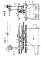
- means for detecting the tension of the safety chain comprise a chassis (54) on which a floating frame (56) can roll, balanced by a counterweight system (50 ), perfectly visible in Figure 4, which tends to drive the floating frame to the right of Figure 5.
- the floating frame (56) is designed to support a shaft (58) which constitutes the axis of rotation of the idler gear (42) of the safety chain (32) located at the top of the descent.
- a detection element (62) is disposed on the chassis (54), so as to be sensitive to the displacement which the floating frame (56) undergoes relative to the chassis (54) as soon as the weight of a load causes an overvoltage in the safety chain (32).
- the chassis (54) has on its front edge and opposite the counterweight system (50), a damping device (70) and stops (72, 74, ) advantageously made of rubber.
- the detection element (62) is an end-of-travel microswitch which, by actuating a brake (66), triggers the stopping of the safety chain (32), and advantageously also the stopping of the main chain drive (18). Braking takes place, by jaws (67), on a disc (64) mounted on the shaft (58) of the idler gear (42) so as to rotate with it.
- the braking system can be hydraulically, pneumatically or electrically operated.
Landscapes
- Devices For Conveying Motion By Means Of Endless Flexible Members (AREA)
- Control Of Conveyors (AREA)
Applications Claiming Priority (2)
| Application Number | Priority Date | Filing Date | Title |
|---|---|---|---|
| FR8215163 | 1982-09-07 | ||
| FR8215163A FR2532632A1 (fr) | 1982-09-07 | 1982-09-07 | Procede et dispositif de securite pour convoyeur aerien a chaine d'entrainement |
Publications (2)
| Publication Number | Publication Date |
|---|---|
| EP0105769A2 true EP0105769A2 (de) | 1984-04-18 |
| EP0105769A3 EP0105769A3 (de) | 1985-09-18 |
Family
ID=9277261
Family Applications (1)
| Application Number | Title | Priority Date | Filing Date |
|---|---|---|---|
| EP83401726A Withdrawn EP0105769A3 (de) | 1982-09-07 | 1983-08-30 | Sicherheitsverfahren und Sicherheitsvorrichtung für Hängebahnförderanlage mit Kettenantrieb |
Country Status (2)
| Country | Link |
|---|---|
| EP (1) | EP0105769A3 (de) |
| FR (1) | FR2532632A1 (de) |
Cited By (5)
| Publication number | Priority date | Publication date | Assignee | Title |
|---|---|---|---|---|
| US6706740B2 (en) | 1999-07-20 | 2004-03-16 | Dow Agrosciences Llc | Fungicidal heterocyclic aromatic amides and their compositions, methods of use and preparation |
| CN105059860A (zh) * | 2015-07-20 | 2015-11-18 | 上海富朗德机械设备有限公司 | 一种重型ems自行小车的爬坡辅助链装置 |
| JP2017178532A (ja) * | 2016-03-30 | 2017-10-05 | 日清食品ホールディングス株式会社 | 物品搬送装置 |
| CN108724145A (zh) * | 2018-07-03 | 2018-11-02 | 武汉奋进智能机器有限公司 | 一种机器人巡视系统 |
| US11932499B2 (en) | 2021-06-24 | 2024-03-19 | Schneider Electric Industries Sas | Mechanical carrier saving in a multicarrier system |
Family Cites Families (5)
| Publication number | Priority date | Publication date | Assignee | Title |
|---|---|---|---|---|
| BE560816A (de) * | ||||
| FR15955E (fr) * | 1912-10-26 | Adolf Bleichert & C Soc | Transporteur aérien électrique | |
| DE209105C (de) * | ||||
| DE281928C (de) * | 1912-06-19 | |||
| DE2455527B2 (de) * | 1974-11-23 | 1978-06-22 | Demag Ag, 4100 Duisburg | Antrieb für einen Kreisförderer |
-
1982
- 1982-09-07 FR FR8215163A patent/FR2532632A1/fr not_active Withdrawn
-
1983
- 1983-08-30 EP EP83401726A patent/EP0105769A3/de not_active Withdrawn
Cited By (7)
| Publication number | Priority date | Publication date | Assignee | Title |
|---|---|---|---|---|
| US6706740B2 (en) | 1999-07-20 | 2004-03-16 | Dow Agrosciences Llc | Fungicidal heterocyclic aromatic amides and their compositions, methods of use and preparation |
| CN105059860A (zh) * | 2015-07-20 | 2015-11-18 | 上海富朗德机械设备有限公司 | 一种重型ems自行小车的爬坡辅助链装置 |
| JP2017178532A (ja) * | 2016-03-30 | 2017-10-05 | 日清食品ホールディングス株式会社 | 物品搬送装置 |
| WO2017169430A1 (ja) * | 2016-03-30 | 2017-10-05 | 日清食品ホールディングス株式会社 | 物品搬送装置 |
| CN108883879A (zh) * | 2016-03-30 | 2018-11-23 | 日清食品控股株式会社 | 物品输送装置 |
| CN108724145A (zh) * | 2018-07-03 | 2018-11-02 | 武汉奋进智能机器有限公司 | 一种机器人巡视系统 |
| US11932499B2 (en) | 2021-06-24 | 2024-03-19 | Schneider Electric Industries Sas | Mechanical carrier saving in a multicarrier system |
Also Published As
| Publication number | Publication date |
|---|---|
| FR2532632A1 (fr) | 1984-03-09 |
| EP0105769A3 (de) | 1985-09-18 |
Similar Documents
| Publication | Publication Date | Title |
|---|---|---|
| FR2539369A1 (fr) | Dispositif cadenceur pour telecabine ou telesiege debrayable | |
| FR2927599A1 (fr) | Systeme d'aide a l'embarquement et/ou au debarquement de passagers a bord de cabines | |
| EP0210897A1 (de) | Steuerungsanlage für Schwerkraft oder Zwangsbewegung, insbesondere für Fallschirmsprungsimulation | |
| EP0462878B1 (de) | Stauförderer mit Arretiervorrichtung für Lastenträger am Übergangsbereich, Lastenträger und Lastenträgerzug für diese | |
| FR2532632A1 (fr) | Procede et dispositif de securite pour convoyeur aerien a chaine d'entrainement | |
| FR2658771A1 (fr) | Plaque tournante perfectionnee pour vehicule automobile. | |
| US6216826B1 (en) | Bank hoist braking apparatus | |
| EP0015211A1 (de) | Vorrichtung zur Geschwindigkeitsstabilisierung einer Seilförderanlage | |
| EP2780209B1 (de) | Mechanisches hubfahrzeug | |
| US4582192A (en) | Conveyor with twin belt synchronizing mechanism | |
| EP0227508B1 (de) | Schienengebundene Transportinstallation mit einer Sicherheitsvorrichtung zur Notbremsung wenigstens eines kabelgezogenen Transportfahrzeugs | |
| WO2009112772A2 (fr) | Wagon de manutention de charges lourdes, notamment de rails, et utilisation d'un tel wagon en présence d'une caténaire | |
| CN213386526U (zh) | 物流分拣系统中应用于消防门处的伸缩机 | |
| JPH01313202A (ja) | 昇降キャブ付き走行クレーン | |
| EP0080150B1 (de) | Förderanlage in Werkstätten für schwere zylindrische Gegenstände | |
| FR2653104A1 (fr) | Equipement de securite pour poste de chargement en vrac dans des vehicules ferroviaires. | |
| WO1989000524A1 (fr) | Systeme de manutention a luges | |
| FR2586985A1 (fr) | Procede de telepherage et telepherique pour sa mise en oeuvre | |
| FR2898321A1 (fr) | Installation de transport par cable aerien | |
| FR2459198A1 (fr) | Procede pour le transport de vehicules de service et dispositif pour la mise en oeuvre de ce procede | |
| FR2527155A1 (fr) | Appareil pour la manutention de charges | |
| EP1719872B1 (de) | Rolltor und Verfahren zur seiner Funktionskontrolle | |
| FR2643321A1 (fr) | Dispositif d'entrainement debrayable pour transporteur du type aerien suspendu ou rampant | |
| FR2610956A1 (fr) | Dispositif de passerelle, muni de systemes d'ascenseurs, notamment pour le franchissement des voies urbaines par les pietons | |
| FR2678571A1 (fr) | Dispositif d'automatisation de l'acces d'un teleporteur. |
Legal Events
| Date | Code | Title | Description |
|---|---|---|---|
| PUAI | Public reference made under article 153(3) epc to a published international application that has entered the european phase |
Free format text: ORIGINAL CODE: 0009012 |
|
| AK | Designated contracting states |
Designated state(s): BE DE GB IT LU NL |
|
| 17P | Request for examination filed |
Effective date: 19840924 |
|
| PUAL | Search report despatched |
Free format text: ORIGINAL CODE: 0009013 |
|
| AK | Designated contracting states |
Designated state(s): BE DE GB IT LU NL |
|
| 17Q | First examination report despatched |
Effective date: 19860326 |
|
| STAA | Information on the status of an ep patent application or granted ep patent |
Free format text: STATUS: THE APPLICATION IS DEEMED TO BE WITHDRAWN |
|
| 18D | Application deemed to be withdrawn |
Effective date: 19870303 |
|
| RIN1 | Information on inventor provided before grant (corrected) |
Inventor name: OUVRE, PIERRE |