EP0105795A2 - Verfahren und Vorrichtung zur Herstellung einer feuerfesten Verkleidung eines metallurgischen Gefässes - Google Patents
Verfahren und Vorrichtung zur Herstellung einer feuerfesten Verkleidung eines metallurgischen Gefässes Download PDFInfo
- Publication number
- EP0105795A2 EP0105795A2 EP83401892A EP83401892A EP0105795A2 EP 0105795 A2 EP0105795 A2 EP 0105795A2 EP 83401892 A EP83401892 A EP 83401892A EP 83401892 A EP83401892 A EP 83401892A EP 0105795 A2 EP0105795 A2 EP 0105795A2
- Authority
- EP
- European Patent Office
- Prior art keywords
- mold
- container
- coating
- installation according
- aggregate
- Prior art date
- Legal status (The legal status is an assumption and is not a legal conclusion. Google has not performed a legal analysis and makes no representation as to the accuracy of the status listed.)
- Withdrawn
Links
Images

Classifications
-
- B—PERFORMING OPERATIONS; TRANSPORTING
- B22—CASTING; POWDER METALLURGY
- B22D—CASTING OF METALS; CASTING OF OTHER SUBSTANCES BY THE SAME PROCESSES OR DEVICES
- B22D41/00—Casting melt-holding vessels, e.g. ladles, tundishes, cups or the like
- B22D41/02—Linings
- B22D41/023—Apparatus used for making or repairing linings
-
- F—MECHANICAL ENGINEERING; LIGHTING; HEATING; WEAPONS; BLASTING
- F27—FURNACES; KILNS; OVENS; RETORTS
- F27D—DETAILS OR ACCESSORIES OF FURNACES, KILNS, OVENS OR RETORTS, IN SO FAR AS THEY ARE OF KINDS OCCURRING IN MORE THAN ONE KIND OF FURNACE
- F27D1/00—Casings; Linings; Walls; Roofs
- F27D1/16—Making or repairing linings ; Increasing the durability of linings; Breaking away linings
- F27D1/1626—Making linings by compacting a refractory mass in the space defined by a backing mould or pattern and the furnace wall
-
- F—MECHANICAL ENGINEERING; LIGHTING; HEATING; WEAPONS; BLASTING
- F27—FURNACES; KILNS; OVENS; RETORTS
- F27D—DETAILS OR ACCESSORIES OF FURNACES, KILNS, OVENS OR RETORTS, IN SO FAR AS THEY ARE OF KINDS OCCURRING IN MORE THAN ONE KIND OF FURNACE
- F27D3/00—Charging; Discharging; Manipulation of charge
- F27D2003/0001—Positioning the charge
-
- F—MECHANICAL ENGINEERING; LIGHTING; HEATING; WEAPONS; BLASTING
- F27—FURNACES; KILNS; OVENS; RETORTS
- F27D—DETAILS OR ACCESSORIES OF FURNACES, KILNS, OVENS OR RETORTS, IN SO FAR AS THEY ARE OF KINDS OCCURRING IN MORE THAN ONE KIND OF FURNACE
- F27D99/00—Subject matter not provided for in other groups of this subclass
- F27D99/0001—Heating elements or systems
- F27D99/0006—Electric heating elements or system
- F27D2099/0008—Resistor heating
Definitions
- the present invention relates to the use of unshaped refractory products for coating by molding the inner part of containers for liquid metal, the coating produced being able to be that which serves as a wear layer or as a safety layer.
- the coating consists of plates of refractory product which must be placed using a mortar to form a waterproof coating, or a refractory concrete placed either by spraying or manually with the trowel.
- the small width of the containers does not always allow projection and, in all cases, the installation of the coating requires the complete cooling of the container to allow access, at the time of the installation of the coating, to the personnel who must enter the container in order to proceed with the placement of the refractory product.
- the assembly must then be subjected to drying before use and, with certain concretes or shaped refractory products, to preheating at high temperature.
- the invention aims to remedy the drawbacks of the prior art by creating a process for molding the refractory lining of containers for liquid metal, which requires practically no manual intervention inside the container.
- the use of a mold allows the installation of the refractory product without waiting for the complete cooling of the container after its previous use.
- the drying of the coating product can then be ensured by equipping the mold with a heating device.
- the invention also relates to an installation for molding a refractory lining, in particular of a container for liquid metal, intended for the implementation of the process defined above, characterized in that it comprises a mold of shape adapted to the geometry of the container and made of several elements to allow free expansion of the mold in use, means for supporting and handling the mold, means for centering and fixing the mold relative to the container, so as to spare between the internal wall of the container and the mold a space intended to receive the refractory concrete, and means for feeding said space in refractory concrete.
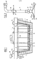
- Fig.1 shows a schematic view in longitudinal section of the installation showing the different elements, with the mold in position in the container;
- Fig.2 is an elevational view of a supply pipe for a mixture of refractory product
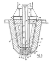
- Fig. 3 is a cross-sectional view of a preferred embodiment of the installation showing the means of placing seat bricks for the tap holes;
- Fig.4 is a sectional view similar to that of Fig.3, of an installation according to the invention provided with an additional mold for the safety coating.
- the installation shown in Fig.1 includes a mold composed of two fixed elements 1 and a free element 2 supported by stiffeners 3 and flexible blades 4, connected to a handling beam 5, provided with gripping ears 5A, on which centering pieces 6 are provided, to standardize the thickness of the product, and fixing pieces 14 to prevent displacement of the mold.
- the free element 2 is arranged between the fixed elements 1.
- Supply pipes 7, of variable number depending on the dimensions of the container C, are connected to the bottom of the mold by quick-disconnect fittings 8 allowing the supply to be uncoupled before the product dries.
- a supply pipe of this type will be described with reference to Fig. 2.
- Removable parts 9 are also provided to protect the openings and to protect the possible locations of baffles 10.
- the installation is completed by a container 11 receiving the mixture of refractory product and water dosed before mixing, said container being connected to positive displacement pumps (not shown). drinking the product.
- a system .12 of heating by electrical resistances is arranged on the internal wall of the elements of the mold and protected by an insulation 13.
- the electrical resistors 12 are formed by a shielded heating cable with mineral insulation consisting of one or more conductive cores embedded in magnesia highly compressed inside a continuous and tight copper sheath.
- this cable is terminated by cold outlets of large cross section and low resistivity.
- the maximum operating temperature is 250 8 C. Any other suitable heating means can also be used.
- a demoulding oil spraying system 16 is also provided, connected to a pressure tank 17.
- Fig.2 there is shown one of the pipes for supplying a mixture of refractory product and water to the installation of Fig.1.
- This pipe which, as in Fig.1, bears the reference numeral 7 is rigid and bent at its upper part.
- This tip of very flared shape has a frustoconical part 21 and an end flange 22 in contact with the underside of the bottom 23 of the mold.
- the end piece 20 is engaged from below in an orifice 24 formed in the bottom of the mold and it comprises latches 25 for immobilizing rotation engaged in radial notches 26 provided in the orifice 24.
- the pipe 7 comprises, at a determined distance from the connector 8, a support flange 26 intended to bear on a support 27 integral with the handling beam 5 so that the end piece 20 is held against the underside of the bottom 23 of the mold .
- the pipe 7 has two welded handles 28 intended to handle the quick coupling 8.
- the tube 7 has a similar connector 29 intended to ensure the connection of the tube 7 with the pumps of the injection system.
- the frusto-conical shape of the end piece 20 allows better flow of the refractory concrete.
- Fig.3 is a cross-sectional view of the installation according to the invention intended to show certain details of the mold shown in Fig.1.
- the installation shown in la.Fig.3 comprises the sheet metal container C in which is placed a permanent or safety coating 30 which can be put in place by means which will be described with reference to Fig.4.
- Resistor heating system 12 is placed in a layer 13 of thermal insulating material supplemented by an insulating cover plate 31.
- a seat brick 33 On the bottom of the container C, at the location of an orifice 32 formed therein, is arranged a seat brick 33, the centering of which is ensured by a ferrule 34.
- This ferrule has a frustoconical outer surface 35 which is in contact with the frustoconical surface of the passage 36 formed in the seat brick 33.
- Each of the fixed parts 2 of the mold includes reinforcements formed by ribs 37.
- each centering ring 34 is fixed a tube 38 in which is housed a rotary shaft 39 provided at its upper part located above the handling beam 5, with an actuating wheel 40 and comprising at its lower end a threaded part 41 cooperating with a nut 42 on which are articulated rods 43 articulated in turn on arms 44 for holding the seat brick.
- the arms 44 are provided with hooks 45 facing outwards and at their opposite ends, they are articulated on lugs 46 integral with the central ferrule 34.
- the drive of the rods 43 can also be provided by electrical, hydraulic, pneumatic or other means.
- Such a design of the mold allows the placement of seat bricks even in a hot container.
- the seat bricks 33 are held by the two arms 44, so that the exact position of the tap holes relative to the mold is thus defined.
- Submerged nozzles can be set up in the same way and be perfectly located relative to the mold.
- FIG. 3 the installation according to the invention is shown in which the refractory concrete constituting the wear lining 47 of the container has been poured and keeps the seat bricks 33 in place.
- the mold comprises on the periphery of its upper part, a seal 48 provided with vent holes 49, this seal allowing a good distribution of the refractory concrete in the interval left free between the mold 2 and the safety coating 30.
- Fig. 4 The installation shown in Fig. 4 is intended to carry out successively, by similar methods, the safety coating and the wear coating of a container.
- This installation comprises a wear coating mold 50 similar to the wear coating mold of the installation shown in FIG. 3.
- the wear coating mold is engaged in a security coating mold 51, the shape and dimensions of which are roughly homothetic with the mold 50.
- This arrangement also allows the use of a single support structure, support and cen trage formed by the beam 5 and its ancillary elements and ensures a constant thickness of the wear coating despite deformations of the outer envelope or displacements of the assembly 50.5 1 relative to the envelope of the container C.
- the bottom 52 of the safety coating mold is in contact with the bottom of the sheet metal container C at the locations of the seat bricks.
- the safety coating mold 51 is fixed to the wear coating mold 50 by fasteners, not shown, which secure the upper edges 53, 54 of the respective molds.
- the safety coating mold 51 has at its upper part a recess 55 intended to create, during the molding of the safety coating, a bearing surface for the seal 48 of the mold 50 of the wear coating.
- the safety coating is produced in the same way as the wear coating, using the same supply pipes with quick couplings and frustoconical ends to introduce between the mold 51 and the container C. A mortar intended to form this coating.
- the two molds 50, 51 form a nested assembly which makes it possible, after molding the safety covering 30, to leave the mold 51 in place for the hydraulic taking of the safety covering and to use the wear covering mold 50 in a container. neighbour.
- the installation according to the invention has been described as being applied to the production of coatings for tundish distributors.
- the method of the invention makes it possible to make a thicker and more insulating safety coating and a thinner and less insulating wear coating, but having a much higher mechanical resistance.
- the speed of the process allows more frequent replacement of the wear layer, and therefore better use of pockets or containers.
- the unshaped refractory product is a magnesium product or of any other nature, containing a chemical or hydraulic binder ensuring it takes hold at the temperatures reached by the heated mold. fant or by that of the container, and a ceramic socket in contact with the liquid metal.
- the grain size of the product is variable depending on its use.
- This process has the advantage of being able to be used with any type of refractory or other concrete, unshaped. It also makes it possible to produce safety, wear and insulating coatings with the same material.
Landscapes
- Engineering & Computer Science (AREA)
- Mechanical Engineering (AREA)
- General Engineering & Computer Science (AREA)
- Furnace Housings, Linings, Walls, And Ceilings (AREA)
- Moulds, Cores, Or Mandrels (AREA)
Applications Claiming Priority (2)
| Application Number | Priority Date | Filing Date | Title |
|---|---|---|---|
| FR8216388 | 1982-09-29 | ||
| FR8216388A FR2533492B1 (fr) | 1982-09-29 | 1982-09-29 | Procede et installation de moulage d'un revetement refractaire de conteneur pour metal liquide |
Publications (2)
| Publication Number | Publication Date |
|---|---|
| EP0105795A2 true EP0105795A2 (de) | 1984-04-18 |
| EP0105795A3 EP0105795A3 (de) | 1985-08-21 |
Family
ID=9277851
Family Applications (1)
| Application Number | Title | Priority Date | Filing Date |
|---|---|---|---|
| EP83401892A Withdrawn EP0105795A3 (de) | 1982-09-29 | 1983-09-27 | Verfahren und Vorrichtung zur Herstellung einer feuerfesten Verkleidung eines metallurgischen Gefässes |
Country Status (2)
| Country | Link |
|---|---|
| EP (1) | EP0105795A3 (de) |
| FR (1) | FR2533492B1 (de) |
Cited By (5)
| Publication number | Priority date | Publication date | Assignee | Title |
|---|---|---|---|---|
| WO1990012666A1 (fr) * | 1989-04-26 | 1990-11-01 | Daussan Et Compagnie | Procede et installation pour realiser un revetement sur les parois interieures d'un recipient metallurgique |
| EP0716894A1 (de) * | 1994-12-19 | 1996-06-19 | Daussan Et Compagnie | Verfahren zum Auftragen von einer aus mindestens zwei Schichten hergestellten Schutzbeschichtung auf die Innenseiten eines metallurgischen Gefässes |
| FR2732915A1 (fr) * | 1995-04-14 | 1996-10-18 | Daussan & Co | Procede pour appliquer a l'interieur d'un recipient metallurgique un revetement de protection comportant au moins deux couches |
| WO1999037423A1 (de) * | 1998-01-22 | 1999-07-29 | Intocast Ag Feuerfest-Produkte Und Giesshilfsmittel | Behälter für metallurgische schmelzen |
| CN119387575A (zh) * | 2024-10-31 | 2025-02-07 | 江苏沙钢钢铁有限公司 | 一种高炉铁水包砌筑方法 |
Families Citing this family (1)
| Publication number | Priority date | Publication date | Assignee | Title |
|---|---|---|---|---|
| CN118893204B (zh) * | 2024-10-09 | 2025-01-07 | 兴化市精密铸钢有限公司 | 一种钢包灌砂设备 |
Family Cites Families (5)
| Publication number | Priority date | Publication date | Assignee | Title |
|---|---|---|---|---|
| FR1258157A (fr) * | 1960-05-28 | 1961-04-07 | Procédé et dispositif pour empêcher la formation de retassures dans le moulage en coquille | |
| FR2050730A5 (en) * | 1969-06-23 | 1971-04-02 | Northrop Corp | Tool for hammering the cylindrical surface - of a bore |
| FR2050736A5 (en) * | 1969-06-23 | 1971-04-02 | Commissariat Energie Atomique | Appts for prodn refractory brusque for - crucibles |
| NL7008651A (de) * | 1970-06-12 | 1970-08-25 | Koninklijke Hoogovens En Staal | |
| US3944193A (en) * | 1972-08-26 | 1976-03-16 | Nippon Steel Corporation | Method and apparatus for forming by vibration a refractory lining of a container for a molten metal |
-
1982
- 1982-09-29 FR FR8216388A patent/FR2533492B1/fr not_active Expired
-
1983
- 1983-09-27 EP EP83401892A patent/EP0105795A3/de not_active Withdrawn
Cited By (9)
| Publication number | Priority date | Publication date | Assignee | Title |
|---|---|---|---|---|
| WO1990012666A1 (fr) * | 1989-04-26 | 1990-11-01 | Daussan Et Compagnie | Procede et installation pour realiser un revetement sur les parois interieures d'un recipient metallurgique |
| FR2646367A1 (fr) * | 1989-04-26 | 1990-11-02 | Daussan & Co | Procede et installation pour realiser un revetement sur les parois interieures d'un recipient metallurgique |
| AU627585B2 (en) * | 1989-04-26 | 1992-08-27 | Daussan Et Compagnie | Production of a monolithic lining in a ladle |
| US5160692A (en) * | 1989-04-26 | 1992-11-03 | Daussan Et Compagnie | Process and plant for producing a lining on the inner walls of a metallurgical vessel |
| EP0716894A1 (de) * | 1994-12-19 | 1996-06-19 | Daussan Et Compagnie | Verfahren zum Auftragen von einer aus mindestens zwei Schichten hergestellten Schutzbeschichtung auf die Innenseiten eines metallurgischen Gefässes |
| FR2728185A1 (fr) * | 1994-12-19 | 1996-06-21 | Daussan & Co | Procede pour appliquer sur les faces interieures d'un recipient metallurgique un revetement de protection comportant au moins deux couches |
| FR2732915A1 (fr) * | 1995-04-14 | 1996-10-18 | Daussan & Co | Procede pour appliquer a l'interieur d'un recipient metallurgique un revetement de protection comportant au moins deux couches |
| WO1999037423A1 (de) * | 1998-01-22 | 1999-07-29 | Intocast Ag Feuerfest-Produkte Und Giesshilfsmittel | Behälter für metallurgische schmelzen |
| CN119387575A (zh) * | 2024-10-31 | 2025-02-07 | 江苏沙钢钢铁有限公司 | 一种高炉铁水包砌筑方法 |
Also Published As
| Publication number | Publication date |
|---|---|
| FR2533492A1 (fr) | 1984-03-30 |
| FR2533492B1 (fr) | 1986-06-13 |
| EP0105795A3 (de) | 1985-08-21 |
Similar Documents
| Publication | Publication Date | Title |
|---|---|---|
| EP0105795A2 (de) | Verfahren und Vorrichtung zur Herstellung einer feuerfesten Verkleidung eines metallurgischen Gefässes | |
| EP0086923A1 (de) | Form, Verfahren und Zusammensetzung für das Abformen durch Einblasen einer feuerfesten verzehrbaren Auskleidung in ein Giessgefäss, bestimmt zur Aufnahme von schmelzflüssigem Metall | |
| FR2657549A1 (fr) | Procede pour appliquer sur les faces interieures d'un recipient metallurgique un revetement de protection comportant au moins deux couches et revetement de protection ainsi obtenu. | |
| FR2548954A1 (fr) | Procede pour realiser une enceinte etanche | |
| EP0682575B1 (de) | Verfahren zur herstellung eines heizelementes zum transport flüssigen metalls, heizelement, verwendung und anwendung | |
| EP0344042B1 (de) | Vorrichtung zum Transport einer metallischen Schmelzzusammensetzung mittels gekühlten Kolbens unter starkem Druck für eine vertikale Druckgiessmaschine | |
| FR2548935A1 (fr) | Procede et installation pour la coulee continue d'un tuyau en fonte a emboitement | |
| US4589633A (en) | Process and installation for moulding a refractory lining of a container for liquid metal | |
| EP0065514A1 (de) | Thermisch isolierendes giessrohr für metallurgisches gefäss. | |
| FR2646367A1 (fr) | Procede et installation pour realiser un revetement sur les parois interieures d'un recipient metallurgique | |
| FR2629838A1 (fr) | Procede et appareil d'introduction d'un materiau fluide dans un bain de metal fondu | |
| CA1094775A (fr) | Embout de raccordement de la tuyauterie d'une pompe electromagnetique et ses applications | |
| FR2573519A1 (fr) | Dispositif de production d'eau chaude | |
| WO1992000157A1 (fr) | Procede pour appliquer sur les faces interieures d'un recipient metallurgique un revetement de protection comportant au moins deux couches, et revetement de protection ainsi obtenu | |
| FR2589228A1 (fr) | Dispositif d'elaboration en continu de materiaux obtenus a partir de substances a l'etat fondu | |
| EP0379410B1 (de) | Einrichtung zur Befestigung und Kühlung eines Graphitblocks einer Graphitkokillenwand | |
| EP1502676B1 (de) | Giesskern auf der Basis von Kaliumborat mit einer Auflösungskammer | |
| FR2533847A1 (fr) | Procede et installation de manutention de moules de fonderie pour la coulee sous basse pression d'alliages metalliques tres oxydables | |
| FR2619032A3 (fr) | Procede et dispositif d'alimentation en metal liquide d'une installation de coulee continue de produits minces en lingotiere a parois mobiles | |
| EP0091533A1 (de) | Giesseinrichtung zur Herstellung von metallischen Gegenständen mit komplizierten Formen durch Schmelzen | |
| FR2509453A1 (fr) | Appareil pour durcir et chauffer un garnissage refractaire | |
| WO2000021701A1 (fr) | Cuve de traitement de metal liquide basculante et son dispositif de liaison etanche avec une goulotte fixe | |
| EP0142402A1 (de) | Anlage zum horizontalen Stranggiessen von Metallen, insbesondere von Stahl | |
| CH392786A (fr) | Procédé pour la coulée continue de lingots et appareil pour sa mise en oeuvre | |
| FR2516642A1 (fr) | Conduit d'alimentation et enveloppe pour appareil de chauffage, et appareil de chauffage de matieres solides |
Legal Events
| Date | Code | Title | Description |
|---|---|---|---|
| PUAI | Public reference made under article 153(3) epc to a published international application that has entered the european phase |
Free format text: ORIGINAL CODE: 0009012 |
|
| AK | Designated contracting states |
Designated state(s): AT BE DE FR GB IT LU NL SE |
|
| PUAL | Search report despatched |
Free format text: ORIGINAL CODE: 0009013 |
|
| AK | Designated contracting states |
Designated state(s): AT BE DE FR GB IT LU NL SE |
|
| 17P | Request for examination filed |
Effective date: 19851107 |
|
| 17Q | First examination report despatched |
Effective date: 19761024 |
|
| D17Q | First examination report despatched (deleted) | ||
| STAA | Information on the status of an ep patent application or granted ep patent |
Free format text: STATUS: THE APPLICATION HAS BEEN WITHDRAWN |
|
| 18W | Application withdrawn |
Withdrawal date: 19871123 |