EP0105848A2 - Vorrichtung zum Rütteln und Ausführen eines Verdichtungsdrucks - Google Patents
Vorrichtung zum Rütteln und Ausführen eines Verdichtungsdrucks Download PDFInfo
- Publication number
- EP0105848A2 EP0105848A2 EP83850201A EP83850201A EP0105848A2 EP 0105848 A2 EP0105848 A2 EP 0105848A2 EP 83850201 A EP83850201 A EP 83850201A EP 83850201 A EP83850201 A EP 83850201A EP 0105848 A2 EP0105848 A2 EP 0105848A2
- Authority
- EP
- European Patent Office
- Prior art keywords
- plate
- joulting
- compaction
- valve
- piston
- Prior art date
- Legal status (The legal status is an assumption and is not a legal conclusion. Google has not performed a legal analysis and makes no representation as to the accuracy of the status listed.)
- Granted
Links
- 238000005056 compaction Methods 0.000 title claims abstract description 16
- 238000004519 manufacturing process Methods 0.000 claims description 4
- 238000007528 sand casting Methods 0.000 claims description 3
- 238000010276 construction Methods 0.000 description 6
- 230000000712 assembly Effects 0.000 description 1
- 238000000429 assembly Methods 0.000 description 1
- 238000010586 diagram Methods 0.000 description 1
- 239000010720 hydraulic oil Substances 0.000 description 1
- 239000000463 material Substances 0.000 description 1
- 238000000465 moulding Methods 0.000 description 1
- 230000008439 repair process Effects 0.000 description 1
- 230000000717 retained effect Effects 0.000 description 1
- 239000000758 substrate Substances 0.000 description 1
Images
Classifications
-
- B—PERFORMING OPERATIONS; TRANSPORTING
- B22—CASTING; POWDER METALLURGY
- B22C—FOUNDRY MOULDING
- B22C15/00—Moulding machines characterised by the compacting mechanism; Accessories therefor
- B22C15/10—Compacting by jarring devices only
- B22C15/14—Compacting by jarring devices only involving pneumatic or hydraulic mechanisms
- B22C15/16—Compacting by jarring devices only involving pneumatic or hydraulic mechanisms the machine having special provision for reducing shock to its frame
- B22C15/18—Compacting by jarring devices only involving pneumatic or hydraulic mechanisms the machine having special provision for reducing shock to its frame by means of separate shock-absorbers
Definitions
- the present invention relates to a device for joulting and the realisation of compaction pressure primarily for the manufacture of sand casting moulds in a flask.
- Prior art machinery for joulting and pressure moulding exhibit an extraordinarily complicated design, with a multiplicity of hydraulic or pneumatic piston and cylinder assemblies both to achieve compaction pressure and to realise the desired joulting. Their mechanics are complicated and consequently give rise to unreliable operation with frequent down-time and subsequent repairs. The complex mechanical construction of these prior art devices also entails relatively high manufacturing costs. Neither do the prior art constructions allow for the use of any pressure medium other than hydraulic oil in cases where it is necessary to create high compaction pressures, greater than.approx. 50 tons.
- One object of the present invention is to realise a device of simple construction and possessing the capability to operate with pneumatic mediums.
- a first plate is provided with an edge surface for cooperation with a cylinder wall which, at the top, is provided with a second plate forming a joulting and/or compaction table; that the space formed between the plates and the cylinder wall is of the same diameter as that of the first- plate, which, in its turn is smal'ler than the second plate, the space being in communication with a pressure medium source by the intermediary of a valve arrangement for both joulting and compaction.
- the second plate displays a piston wall of considerably smaller diameter than the first-mentioned cylinder wall; that the piston wall extends through the first plate and is, in the proximity of the underface of the second plate, in communication with the above-mentioned space; and that the communication is coupled to the pressure medium source by the intermediary of the cylinder arrangement.
- the piston wall has a portion possessing substantially the same diameter as a corresponding hole in the first plate and a length which corresponds to the desired lifting height of the second plate. Furthermore, The piston wall is provided, after the above-mentioned portion, with a further portion of lesser diameter than the hole in the first plate far realising pressure relief in the event that the desired lifting height be exceeded.
- a device for joulting and the generation of compaction pressure will be of extremely simple construction which is thereby considerably more reliable from the point of view of operation than prior art constructions.
- the present invention also makes possible the utilazation of a per se conventional compaction pressure source of the type which is available on most plants for the manufacture of sand casting moulds.
- a device according to the present invention may be powered pneumatically in its entirety.
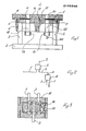
- Fig. 1 is a schematic side elevation, partly in section, through one embodiment of a device according to the present invention.
- Fig. 2 is a diagram of a valve arrangement of the device according to the present invention illustrated in Fig. 1.
- Fig. 3 is a schematic cross-section through one of the valves in the arrangement according to Fig. 2.
- a device according to the present invention illustrated in Fig. 1 is shown merely-in principle and consists of a piston plate 1 which is placed on a base 2 - with supports 3 and 4.
- the base 2 may consist of a plate or a number of joists or beams which are arranged to cooperate with a number of supports 3 and a number of supports 4, the joists and supports being arranged to form as stable a substrate for the piston plate 1 as possible.
- the supports and, possibly, the joists may be replaced by walls.
- the piston plate 1 is circular and has an edge surface 5 intended for cooperation with the inner face of the cylinder wall 6. To this end, the edge surface 5 is provided with a suitable cylinder gasket 7 which may be of any optional, suitable type.
- the cylinder face 6 has a cylinder top which forms a joulting table plate 8. Between the piston plate 1 and the . joulting table plate 8, which also serves as a compaction plate, there are disposed shock-absorbing members 9 and 10. These shockabsorbing members may consists of rods, plates or rings of resiliently yieldable material, for example rubber.
- the plate 8 is, furthermore, provided with at least two rods 11 and 12 which are fixedly retained in the plate 8 and extend through holes in the plate 1, and, at that end in facing relationship to the plate 8, are provided with stopping members 13 and 14. These stopping members 13 and 14 may consist of nuts threaded on the ends of the rods 11 and 12. These nuts ensure that the cylinder face 6 cannot rise above the plate 1.
- a piston wall 15 which extends through a corresponding hole in the plate 1.
- the fit between the hole in the plate 1 and the piston wall 15 is preferably of the order of magnitude of a few hundredths of a millimetre.
- the wall is of smaller diameter than the hole in the plate 1, whereby the space 16 formed between the plates 1 and 8 and the cylinder face 6 will be relieved of the pressure medium prevailing therein when the piston wall 15 of larger diameter leaves the hole in the plae 1.
- a duct 17 which, at the portion most proximal the plate 8, is in open communication with the space 16 and whose opposite end is connected to a pressure medium source by the intermediary of a valve arrangement of the type illustrated in Fig. 2.
- the pressure medium source is a pneumatic medium, for example, compressed air, at a pressure of, for example, 18 atp.
- the compaction pressure attainable in the device illustrated in Fig. 1 will amount to approx. 90 tons, and if the diameter of the space 16 is increased by 200 mm, the pressure attainable with 18 atp will be approx. 140 ton. A further increase of the diameter by 200 mm will give a compaction pressure of approx. 200 tons with the same medium source.
- the pressure in the pressure medium source is steplessly adjustable from, for example, 0 to 18 atp by means of a per se known pressure regulator whereby the compaction pressure may also be varied from 0 to maximum.
- the device illustrated in Fig. 1 may also be utilized for realising joulting.
- a joulting amplitude transducer G1 which in its turn is connected to an electronics unit for controlling the valve arrangement illustrated in Fig. 2.
- valve A is a solenoid valve for feeding compressed air from the port 1 to the port 2, the port 2 being in communication with the duct 17 and, by this intermediary, with the space 16.
- the port 3 in valve A is, furthermore, in communication with the port 2 in valve B which is also a solenoid valve whose construction is illustrated in greater detail in Fig. 3. Whilst the valve A is a standard on-off valve for the contemplated pressure of the pressure medium, the valve B ⁇ is a short-stroke valve for large volumes. The valve B essentially serves to realise the joulting motion of the plate 8.
- valve B consists of a piston 18 which, by means of a spring 19, is urged to the left, in which event the output port 3 will be in communication with the atmosphere, like the output port 2.
- valve B If the valve B is impressed with an electric impulse from the electronics circuit, the piston 18 will be switched to the right against the action of the spring 19, whereby the port 3 will be closed and the port 1 will be placed in communication with the port 2, so that pressure medium may be fed via the port 2 and ports 3 and 2 in valve A, the piston 18 being returned by the action of the spring 19 to the position illustrated in Fig. 3 as soon as the electric impulse is discontinued.
- the length of the electric impulse may, thus, correspond to the amplitude of the joulting motion.
- the amplitude transducer G1 is preferably of such type as to permit a maximum motion of 2 mm .
- time-lag means which may be adjustable within a time period of from 0.01 to 0.5 sec.,giving a steplessly adjustable vibration or motion amplitude from the above-disclosed 2 mm and upwards.
Landscapes
- Engineering & Computer Science (AREA)
- Mechanical Engineering (AREA)
- Paper (AREA)
- Apparatuses For Generation Of Mechanical Vibrations (AREA)
- Spinning Or Twisting Of Yarns (AREA)
- Crushing And Grinding (AREA)
- Portable Nailing Machines And Staplers (AREA)
- Road Paving Machines (AREA)
- Investigation Of Foundation Soil And Reinforcement Of Foundation Soil By Compacting Or Drainage (AREA)
- Fluid-Pressure Circuits (AREA)
- Casting Devices For Molds (AREA)
Priority Applications (1)
| Application Number | Priority Date | Filing Date | Title |
|---|---|---|---|
| AT83850201T ATE33773T1 (de) | 1982-08-09 | 1983-07-25 | Vorrichtung zum ruetteln und ausfuehren eines verdichtungsdrucks. |
Applications Claiming Priority (2)
| Application Number | Priority Date | Filing Date | Title |
|---|---|---|---|
| SE8204623A SE439741B (sv) | 1982-08-09 | 1982-08-09 | Anordning for skakning och astadkommande av presstryck for tillverkning av gjutformar av sand |
| SE8204623 | 1982-08-09 |
Publications (3)
| Publication Number | Publication Date |
|---|---|
| EP0105848A2 true EP0105848A2 (de) | 1984-04-18 |
| EP0105848A3 EP0105848A3 (en) | 1985-07-03 |
| EP0105848B1 EP0105848B1 (de) | 1988-04-27 |
Family
ID=20347502
Family Applications (1)
| Application Number | Title | Priority Date | Filing Date |
|---|---|---|---|
| EP83850201A Expired EP0105848B1 (de) | 1982-08-09 | 1983-07-25 | Vorrichtung zum Rütteln und Ausführen eines Verdichtungsdrucks |
Country Status (5)
| Country | Link |
|---|---|
| US (1) | US4582113A (de) |
| EP (1) | EP0105848B1 (de) |
| AT (1) | ATE33773T1 (de) |
| DE (1) | DE3376391D1 (de) |
| SE (1) | SE439741B (de) |
Family Cites Families (5)
| Publication number | Priority date | Publication date | Assignee | Title |
|---|---|---|---|---|
| US1560145A (en) * | 1920-08-07 | 1925-11-03 | Henry L Demmler | Molding machine |
| US1778609A (en) * | 1927-12-05 | 1930-10-14 | Robert F Ringle | Molding machine |
| US2624084A (en) * | 1948-10-21 | 1953-01-06 | John R Row | Mold and coremaking machine |
| US2652607A (en) * | 1952-04-24 | 1953-09-22 | Spo Inc | Jolt and draw foundry machine |
| US3815662A (en) * | 1967-10-02 | 1974-06-11 | Sherwin Williams Co | Jolt table shaped for supporting cope top and telescoping into drag |
-
1982
- 1982-08-09 SE SE8204623A patent/SE439741B/sv not_active IP Right Cessation
-
1983
- 1983-07-25 DE DE8383850201T patent/DE3376391D1/de not_active Expired
- 1983-07-25 EP EP83850201A patent/EP0105848B1/de not_active Expired
- 1983-07-25 AT AT83850201T patent/ATE33773T1/de active
- 1983-07-28 US US06/518,276 patent/US4582113A/en not_active Expired - Fee Related
Also Published As
| Publication number | Publication date |
|---|---|
| SE8204623D0 (sv) | 1982-08-09 |
| US4582113A (en) | 1986-04-15 |
| ATE33773T1 (de) | 1988-05-15 |
| EP0105848A3 (en) | 1985-07-03 |
| DE3376391D1 (en) | 1988-06-01 |
| SE8204623L (sv) | 1984-02-10 |
| EP0105848B1 (de) | 1988-04-27 |
| SE439741B (sv) | 1985-07-01 |
Similar Documents
| Publication | Publication Date | Title |
|---|---|---|
| JPH0442010Y2 (de) | ||
| US4270890A (en) | Apparatus for controlling the height of pressed workpieces of ceramic powder or other material in a press | |
| US3865359A (en) | Vacuum apparatus | |
| JPS6397509U (de) | ||
| ES8200315A1 (es) | Cabezal de corte para maquina de corte de vidrio | |
| US4006655A (en) | Device for protecting tools and workpieces from damage on a hydraulically or pneumatically operated stamping press | |
| US4582113A (en) | Device for vibration and realizing compaction pressure | |
| CA2031770A1 (en) | Position-controlled proportional directional valve | |
| GB1535838A (en) | Pneumatically powered and cushioned driving tools | |
| US2380152A (en) | Pneumatic power device | |
| US5476136A (en) | Device for compacting granular molding material | |
| JP3681433B2 (ja) | パンチプレス及び上型 | |
| ES2088342A2 (es) | Prensa de vibrocompactacion para el moldeo al vacio de losas o bloques de piedra o material granular ceramico. | |
| US4825681A (en) | Pneumatic press counterbalance and cushion construction | |
| US3599561A (en) | Pneumatic press | |
| US4878534A (en) | Apparatus for the compacting of granular molding materials | |
| SU820648A3 (ru) | Автоматическое устройство дл изгОТОВлЕНи лиТЕйНыХ фОРМ | |
| US3681958A (en) | High pressure forming press | |
| US5076085A (en) | Apparatus for forming a metallic unit having a concave portion bounded by a peripheral edge | |
| JP4299723B2 (ja) | 負圧プレス装置 | |
| SU1606235A1 (ru) | Штамп дл обработки листовых заготовок и профилей | |
| US4754955A (en) | Air cushion snubber apparatus | |
| JPS6045998B2 (ja) | 粉末原料圧縮成形プレス及びそのプレスを用いた粉末原料の圧縮成形方法 | |
| CN216767936U (zh) | 具有缓冲功能的液压缸 | |
| US3575232A (en) | Foundry mold-making apparatus |
Legal Events
| Date | Code | Title | Description |
|---|---|---|---|
| PUAI | Public reference made under article 153(3) epc to a published international application that has entered the european phase |
Free format text: ORIGINAL CODE: 0009012 |
|
| AK | Designated contracting states |
Designated state(s): AT BE CH DE FR GB IT LI LU NL |
|
| 17P | Request for examination filed |
Effective date: 19841017 |
|
| PUAL | Search report despatched |
Free format text: ORIGINAL CODE: 0009013 |
|
| AK | Designated contracting states |
Designated state(s): AT BE CH DE FR GB IT LI LU NL |
|
| 17Q | First examination report despatched |
Effective date: 19860424 |
|
| R17C | First examination report despatched (corrected) |
Effective date: 19870202 |
|
| GRAA | (expected) grant |
Free format text: ORIGINAL CODE: 0009210 |
|
| AK | Designated contracting states |
Kind code of ref document: B1 Designated state(s): AT BE CH DE FR GB IT LI LU NL |
|
| REF | Corresponds to: |
Ref document number: 33773 Country of ref document: AT Date of ref document: 19880515 Kind code of ref document: T |
|
| REF | Corresponds to: |
Ref document number: 3376391 Country of ref document: DE Date of ref document: 19880601 |
|
| ITF | It: translation for a ep patent filed | ||
| PG25 | Lapsed in a contracting state [announced via postgrant information from national office to epo] |
Ref country code: LU Free format text: LAPSE BECAUSE OF NON-PAYMENT OF DUE FEES Effective date: 19880731 |
|
| ET | Fr: translation filed | ||
| PLBE | No opposition filed within time limit |
Free format text: ORIGINAL CODE: 0009261 |
|
| STAA | Information on the status of an ep patent application or granted ep patent |
Free format text: STATUS: NO OPPOSITION FILED WITHIN TIME LIMIT |
|
| 26N | No opposition filed | ||
| PGFP | Annual fee paid to national office [announced via postgrant information from national office to epo] |
Ref country code: AT Payment date: 19900716 Year of fee payment: 8 |
|
| PGFP | Annual fee paid to national office [announced via postgrant information from national office to epo] |
Ref country code: GB Payment date: 19900724 Year of fee payment: 8 |
|
| PGFP | Annual fee paid to national office [announced via postgrant information from national office to epo] |
Ref country code: BE Payment date: 19900727 Year of fee payment: 8 |
|
| PGFP | Annual fee paid to national office [announced via postgrant information from national office to epo] |
Ref country code: FR Payment date: 19900730 Year of fee payment: 8 |
|
| ITTA | It: last paid annual fee | ||
| PGFP | Annual fee paid to national office [announced via postgrant information from national office to epo] |
Ref country code: NL Payment date: 19900731 Year of fee payment: 8 |
|
| PGFP | Annual fee paid to national office [announced via postgrant information from national office to epo] |
Ref country code: DE Payment date: 19900830 Year of fee payment: 8 |
|
| PGFP | Annual fee paid to national office [announced via postgrant information from national office to epo] |
Ref country code: CH Payment date: 19901008 Year of fee payment: 8 |
|
| PG25 | Lapsed in a contracting state [announced via postgrant information from national office to epo] |
Ref country code: GB Effective date: 19910725 Ref country code: AT Effective date: 19910725 |
|
| PG25 | Lapsed in a contracting state [announced via postgrant information from national office to epo] |
Ref country code: LI Effective date: 19910731 Ref country code: CH Effective date: 19910731 Ref country code: BE Effective date: 19910731 |
|
| BERE | Be: lapsed |
Owner name: BERGSTROM NILS GUSTAV HENRY Effective date: 19910731 |
|
| PG25 | Lapsed in a contracting state [announced via postgrant information from national office to epo] |
Ref country code: NL Effective date: 19920201 |
|
| NLV4 | Nl: lapsed or anulled due to non-payment of the annual fee | ||
| GBPC | Gb: european patent ceased through non-payment of renewal fee | ||
| PG25 | Lapsed in a contracting state [announced via postgrant information from national office to epo] |
Ref country code: FR Effective date: 19920331 |
|
| REG | Reference to a national code |
Ref country code: CH Ref legal event code: PL |
|
| PG25 | Lapsed in a contracting state [announced via postgrant information from national office to epo] |
Ref country code: DE Effective date: 19920401 |
|
| REG | Reference to a national code |
Ref country code: FR Ref legal event code: ST |