EP0105938A1 - Support de tubes d'un faisceau de tubes à l'intérieur d'une enveloppe - Google Patents
Support de tubes d'un faisceau de tubes à l'intérieur d'une enveloppe Download PDFInfo
- Publication number
- EP0105938A1 EP0105938A1 EP82109265A EP82109265A EP0105938A1 EP 0105938 A1 EP0105938 A1 EP 0105938A1 EP 82109265 A EP82109265 A EP 82109265A EP 82109265 A EP82109265 A EP 82109265A EP 0105938 A1 EP0105938 A1 EP 0105938A1
- Authority
- EP
- European Patent Office
- Prior art keywords
- tubes
- support rods
- tube bundle
- support
- cross
- Prior art date
- Legal status (The legal status is an assumption and is not a legal conclusion. Google has not performed a legal analysis and makes no representation as to the accuracy of the status listed.)
- Withdrawn
Links
- XEEYBQQBJWHFJM-UHFFFAOYSA-N Iron Chemical compound [Fe] XEEYBQQBJWHFJM-UHFFFAOYSA-N 0.000 claims description 14
- 229910052742 iron Inorganic materials 0.000 claims description 7
- 238000010276 construction Methods 0.000 description 2
- RZVAJINKPMORJF-UHFFFAOYSA-N Acetaminophen Chemical compound CC(=O)NC1=CC=C(O)C=C1 RZVAJINKPMORJF-UHFFFAOYSA-N 0.000 description 1
- 239000003990 capacitor Substances 0.000 description 1
- 238000005336 cracking Methods 0.000 description 1
- 230000001419 dependent effect Effects 0.000 description 1
- 238000005457 optimization Methods 0.000 description 1
- 230000000630 rising effect Effects 0.000 description 1
- 230000003319 supportive effect Effects 0.000 description 1
Images
Classifications
-
- F—MECHANICAL ENGINEERING; LIGHTING; HEATING; WEAPONS; BLASTING
- F28—HEAT EXCHANGE IN GENERAL
- F28F—DETAILS OF HEAT-EXCHANGE AND HEAT-TRANSFER APPARATUS, OF GENERAL APPLICATION
- F28F9/00—Casings; Header boxes; Auxiliary supports for elements; Auxiliary members within casings
- F28F9/007—Auxiliary supports for elements
- F28F9/013—Auxiliary supports for elements for tubes or tube-assemblies
- F28F9/0135—Auxiliary supports for elements for tubes or tube-assemblies formed by grids having only one tube per closed grid opening
Definitions
- the invention relates to a holder for the tubes of a tube bundle within a container, in particular for a heat exchanger consisting of jacket and tube bundle or a reactor vessel, with support rods arranged in tiers, which extend through the spaces between parallel rows of tubes and the tubes on their outer circumference radially supportive touch.
- the support rods of each tier are usually attached to a ring that surrounds the tube bundle and is attached to the inner wall of the container.
- the support rods are arranged in the interior of the container through which a medium flows, the support rods represent a flow resistance which causes a pressure drop.
- the levels of straight support bars, which cross each other in stages, have therefore been arranged at greater distances from one another (US Pat. No. 4,127,165).
- DE-OS 27 06 049 US 4 127 165
- each level of straight support rods consists of a plurality of intersecting support rods in closely spaced planes.
- the purpose of supporting tubes of a tube bundle in container construction along their length is to protect the tubes through which a second medium flows against cracking and breakage.
- the vibration problem is in the foreground, because the degree of non-uniformity of feed pumps and the level disturbance of the longitudinal flow due to the support rods can cause harmful resonance vibrations in the pipes.
- the tubes are additionally subjected to buckling, since the medium flowing through the tubes is under high pressure, which oppositely loads the plates delimiting the interior of the container, in which the ends of the tubes are fastened.
- the object of the invention is to provide a holder for the tubes of a tube bundle in container construction, in which the tubes have as few degrees of freedom as possible in the radial direction within one level of support rods.
- the support rods of each floor are designed in such a way that they touch the tubes over a centering angle.
- This line contact on a wrap angle more or less significantly reduces the possible degrees of freedom of the pipe compared to the previous mounting of the pipes with straight support rods.
- the radial support of the tubes can be optimized according to the invention in that the support rods have a cross section with parallel side surfaces, which then form a flat radial support of the tubes on the centering angle dependent on the waveform of the support rods.
- the waveform of support rods of round or angular cross-section in accordance with the invention is used in conjunction with the known feature of two groups of support rods which cross each other and are arranged in closely adjacent planes, an almost all-round support is obtained on a short length of the tubes Pipes over four circumferentially distributed centering angles, ie the pipes are firmly clamped within each holder in the sense of the statistics, whereby the calculation of the pipes on kink changes fundamentally, with the result that the thickness of the pipe wall can be reduced by reducing the outer diameter, which in turn offers the possibility of more pipes within one To provide tube bundle.
- the firm clamping of the tubes within a holder with intersecting groups of corrugated support rods is of course more effective when using upright laid flat rods with flat support via the centering angle than when using round rods.
- a most effective fixed clamping of pipes via wave-shaped support rods with a rectangular cross-section is obtained in that the support rods according to the further invention are laid in a common plane in the form of a wave iron grating, in that the rods penetrate in halves on both sides at the intersection points.
- wave iron grille is derived from the well-known doormats from intersecting corrugated flat bars, such as those used in front of building exterior doors.
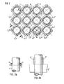
- the corrugated support rods 2, 3, 4 and 5 have a radius of curvature on the shafts which corresponds to the radius R of the outer circumference of the tubes 1. In the case of the thickness of the support rods provided in FIG.
- FIG. 1 initially stands for support rods 2 to 5 with the usual circular cross-section (FIG. 2a), which in the sense of inventing to improve the radial support of the tubes 1 between the support rods and the tubes has a curved, linear contact is present, namely when the support rods intersect in two closely spaced planes and support rods in all spaces between parallel rows of tubes at four circumferentially distributed centering angles ⁇ per tube.
- a firm clamping of the tubes is obtained if the support rods 2 'to 5' have a cross section with parallel side surfaces, for example are flat rods. Then a flat support takes place in each plane of the support rods on the centering angles ⁇ (FIG. 2b).
- the pipes 1 laid according to a square pattern according to FIG. 1 entail that relatively large free flow cross-sections 7 and gusset-shaped flow cross-sections 8 are formed for each holder, which also include increasing thickness of the support rods and smaller pipe distances. These relationships make it possible to optimize the radial support of the pipes at the expense of the flow cross-sections or vice versa.
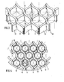
- FIG. 3 shows a so-called wave iron grille, in which the support rods 10, 11 with support rods 12, 13 have a rectangular cross section, that is to say flat rods, and can therefore be arranged in a common plane because they are halved on both sides at the intersection points 14 Penetrate slots 15, 16.
- Fig. 4 shows the wave iron grid according to Fig. 3 with inserted tubes 1 of a tube bundle, which are laid in an equilateral triangle pattern. With this arrangement of tubes, a maximum number of tubes can be accommodated within a tube bundle, which is why this triangular pattern is preferred for reactor vessels.
- the support rods 10 and 11 wrap around each tube at two diametrical centering angles ⁇ 1 , which are supplemented by centering angles ⁇ 2 , which are assigned to the support rods 12 and 13.
- This optimal fixed clamping results from the fact that the thickness of the support rods is approximately equal to the clear distance between adjacent tubes.
- the flow cross-sections within each mounting plane are reduced to the gusset-shaped free spaces 18, which would be sufficient for capacitors, for example.
- Fig. 4 also shows the attachment of the support rods to a ring 17, which in turn is attached to the inner wall of the container shell, not shown.
Landscapes
- Engineering & Computer Science (AREA)
- Physics & Mathematics (AREA)
- Thermal Sciences (AREA)
- Mechanical Engineering (AREA)
- General Engineering & Computer Science (AREA)
- Supports For Pipes And Cables (AREA)
Priority Applications (1)
| Application Number | Priority Date | Filing Date | Title |
|---|---|---|---|
| EP82109265A EP0105938A1 (fr) | 1982-10-07 | 1982-10-07 | Support de tubes d'un faisceau de tubes à l'intérieur d'une enveloppe |
Applications Claiming Priority (1)
| Application Number | Priority Date | Filing Date | Title |
|---|---|---|---|
| EP82109265A EP0105938A1 (fr) | 1982-10-07 | 1982-10-07 | Support de tubes d'un faisceau de tubes à l'intérieur d'une enveloppe |
Publications (1)
| Publication Number | Publication Date |
|---|---|
| EP0105938A1 true EP0105938A1 (fr) | 1984-04-25 |
Family
ID=8189261
Family Applications (1)
| Application Number | Title | Priority Date | Filing Date |
|---|---|---|---|
| EP82109265A Withdrawn EP0105938A1 (fr) | 1982-10-07 | 1982-10-07 | Support de tubes d'un faisceau de tubes à l'intérieur d'une enveloppe |
Country Status (1)
| Country | Link |
|---|---|
| EP (1) | EP0105938A1 (fr) |
Cited By (5)
| Publication number | Priority date | Publication date | Assignee | Title |
|---|---|---|---|---|
| US5033542A (en) * | 1989-02-28 | 1991-07-23 | Mtu Motoren-Und Turbinen-Union | Spacer supports for tubes of a matrix of a heat exchanger |
| US5449037A (en) * | 1993-12-08 | 1995-09-12 | Brown Fintube Corporation | Heat exchanger tube spacer, separator, and support |
| US20170321971A1 (en) * | 2014-12-30 | 2017-11-09 | Joint Stock Company "Akme-Engineering" | Heat Exchanger Tube Spacing Device (Varinats) |
| WO2022147070A1 (fr) * | 2020-12-30 | 2022-07-07 | Scientific Design Company, Inc. | Support de grille ondulée pour réacteur à point d'ébullition vertical |
| CN115752068A (zh) * | 2022-09-28 | 2023-03-07 | 福建立信换热设备制造股份公司 | 一种热交换器绕片管的支撑组件及采用该支撑组件的热交换器 |
Citations (5)
| Publication number | Priority date | Publication date | Assignee | Title |
|---|---|---|---|---|
| GB1101953A (en) * | 1964-10-20 | 1968-02-07 | Babcock & Wilcox Co | Improvements in or relating to rod, pin and tube assemblies |
| GB1223045A (en) * | 1967-07-31 | 1971-02-17 | Alcatel S A Soc | Suppression of vibrations in tubes |
| DE2045353A1 (de) * | 1969-09-26 | 1971-04-15 | Waagner Biro AG, Wien | Rohrbündel Wärmetauscher |
| DE2052837A1 (en) * | 1970-10-21 | 1972-04-27 | Frank W | Heat exchanger tube fixing - comprises flexible tubes transversely between rows of exchanger tubes |
| FR2130384A1 (fr) * | 1971-03-19 | 1972-11-03 | Ca Atomic Energy Ltd |
-
1982
- 1982-10-07 EP EP82109265A patent/EP0105938A1/fr not_active Withdrawn
Patent Citations (5)
| Publication number | Priority date | Publication date | Assignee | Title |
|---|---|---|---|---|
| GB1101953A (en) * | 1964-10-20 | 1968-02-07 | Babcock & Wilcox Co | Improvements in or relating to rod, pin and tube assemblies |
| GB1223045A (en) * | 1967-07-31 | 1971-02-17 | Alcatel S A Soc | Suppression of vibrations in tubes |
| DE2045353A1 (de) * | 1969-09-26 | 1971-04-15 | Waagner Biro AG, Wien | Rohrbündel Wärmetauscher |
| DE2052837A1 (en) * | 1970-10-21 | 1972-04-27 | Frank W | Heat exchanger tube fixing - comprises flexible tubes transversely between rows of exchanger tubes |
| FR2130384A1 (fr) * | 1971-03-19 | 1972-11-03 | Ca Atomic Energy Ltd |
Cited By (10)
| Publication number | Priority date | Publication date | Assignee | Title |
|---|---|---|---|---|
| US5033542A (en) * | 1989-02-28 | 1991-07-23 | Mtu Motoren-Und Turbinen-Union | Spacer supports for tubes of a matrix of a heat exchanger |
| US5449037A (en) * | 1993-12-08 | 1995-09-12 | Brown Fintube Corporation | Heat exchanger tube spacer, separator, and support |
| US20170321971A1 (en) * | 2014-12-30 | 2017-11-09 | Joint Stock Company "Akme-Engineering" | Heat Exchanger Tube Spacing Device (Varinats) |
| US10563929B2 (en) * | 2014-12-30 | 2020-02-18 | Joint Stock Company “Akme-Engineering” | Heat exchanger tube spacing device (varinats) |
| WO2022147070A1 (fr) * | 2020-12-30 | 2022-07-07 | Scientific Design Company, Inc. | Support de grille ondulée pour réacteur à point d'ébullition vertical |
| CN116802454A (zh) * | 2020-12-30 | 2023-09-22 | 科学设计有限公司 | 用于立式沸腾反应器的波纹状格栅支架 |
| JP2024502014A (ja) * | 2020-12-30 | 2024-01-17 | サイエンティフィック・デザイン・カンパニー・インコーポレーテッド | 垂直沸騰反応器用の波形の格子状支持体 |
| US12030028B2 (en) | 2020-12-30 | 2024-07-09 | Scientific Design Company, Inc. | Corrugated grid support for vertical boiling reactor |
| EP4271957A4 (fr) * | 2020-12-30 | 2024-09-04 | Scientific Design LLC | Support de grille ondulée pour réacteur à point d'ébullition vertical |
| CN115752068A (zh) * | 2022-09-28 | 2023-03-07 | 福建立信换热设备制造股份公司 | 一种热交换器绕片管的支撑组件及采用该支撑组件的热交换器 |
Similar Documents
| Publication | Publication Date | Title |
|---|---|---|
| DE2707702C2 (de) | Stützvorrichtung für eine Vielzahl von Röhren in einem Wärmeaustauscher | |
| DE2601645A1 (de) | Waermetauscher | |
| DE2045353B2 (de) | Roehrenwaermetauscher | |
| DE69110562T2 (de) | Stabschirm für einen Wärmetauscher. | |
| CH477666A (de) | Wärmeübertrager | |
| DE1924462C3 (de) | Druckgefäß | |
| DE2106342C3 (de) | Brennstoffelement für einen Atomkernreaktor mit parallelen Brennstoffstäben | |
| EP0105938A1 (fr) | Support de tubes d'un faisceau de tubes à l'intérieur d'une enveloppe | |
| DE1439775A1 (de) | Brennstoffstabbuendel fuer Kernreaktoren | |
| DE2706049C2 (de) | Vorrichtung zum Lagern einer Vielzahl von Röhren in einem Wärmeaustauscher | |
| DE2550035C3 (de) | Wärmetauscher mit einer Vielzahl mit Abstand voneinander angeordneter Wärmetauschmedium-Strömungsrohre | |
| DE2804113A1 (de) | Halterung zur befestigung der rohre eines waermetauschers | |
| DE2459472B1 (de) | Gasbeheizter dampferzeuger, insbesondere fuer kernreaktoranlagen | |
| DE3219297C2 (de) | Wärmetauscher, insbesondere Heissgaskühler für Helium | |
| DE3008456C2 (fr) | ||
| DE2308317C3 (de) | Wärmetauscher großer Abmessung für den Betrieb bei hohen Temperaturen und Drücken | |
| CH632583A5 (de) | Rohrbuendel zur waermeuebertragung durch beruehrung. | |
| DE2541399C2 (de) | Rohrbündel-Wärmeaustauscher | |
| DE2734060A1 (de) | Waermetauscher mit einem rohrbuendel aus einer vielzahl von schraubenfoermig gewendelten rohren | |
| CH428814A (de) | Abstützung für ein Bündel quer angeströmter Rohre eines Wärmeübertragers | |
| DE1960965C3 (de) | Röhrenwärmetauscher für zu Kesselsteinansatz oder Ablagerungen neigende Flüssigkeiten | |
| DE2129809A1 (de) | Siedewasserreaktorkern | |
| DE1108715B (de) | Rohrunterstuetzung fuer Roehrenbuendel von Waermetauschern | |
| DE1806432C3 (de) | Abstandhaltegitter für ein Kernreaktor-Brennstoffelement | |
| DE1514993C3 (de) | Kernreaktor-Brennelement mit einem Bündel von parallelen Brennstoffstäben |
Legal Events
| Date | Code | Title | Description |
|---|---|---|---|
| PUAI | Public reference made under article 153(3) epc to a published international application that has entered the european phase |
Free format text: ORIGINAL CODE: 0009012 |
|
| AK | Designated contracting states |
Designated state(s): AT BE DE FR GB IT NL SE |
|
| STAA | Information on the status of an ep patent application or granted ep patent |
Free format text: STATUS: THE APPLICATION IS DEEMED TO BE WITHDRAWN |
|
| 18D | Application deemed to be withdrawn |
Effective date: 19850325 |
|
| RIN1 | Information on inventor provided before grant (corrected) |
Inventor name: LEFFER, HANS GEORG, DIPL.-ING. |