EP0105967B1 - Méthode et dispositif pour l'investigation de la structure et de la perméabilité dans les domaines des sols et des rochers - Google Patents
Méthode et dispositif pour l'investigation de la structure et de la perméabilité dans les domaines des sols et des rochers Download PDFInfo
- Publication number
- EP0105967B1 EP0105967B1 EP82109653A EP82109653A EP0105967B1 EP 0105967 B1 EP0105967 B1 EP 0105967B1 EP 82109653 A EP82109653 A EP 82109653A EP 82109653 A EP82109653 A EP 82109653A EP 0105967 B1 EP0105967 B1 EP 0105967B1
- Authority
- EP
- European Patent Office
- Prior art keywords
- measuring
- dam
- injection
- gas
- bores
- Prior art date
- Legal status (The legal status is an assumption and is not a legal conclusion. Google has not performed a legal analysis and makes no representation as to the accuracy of the status listed.)
- Expired
Links
Images

Classifications
-
- E—FIXED CONSTRUCTIONS
- E02—HYDRAULIC ENGINEERING; FOUNDATIONS; SOIL SHIFTING
- E02D—FOUNDATIONS; EXCAVATIONS; EMBANKMENTS; UNDERGROUND OR UNDERWATER STRUCTURES
- E02D1/00—Investigation of foundation soil in situ
- E02D1/08—Investigation of foundation soil in situ after finishing the foundation structure
-
- E—FIXED CONSTRUCTIONS
- E21—EARTH OR ROCK DRILLING; MINING
- E21B—EARTH OR ROCK DRILLING; OBTAINING OIL, GAS, WATER, SOLUBLE OR MELTABLE MATERIALS OR A SLURRY OF MINERALS FROM WELLS
- E21B47/00—Survey of boreholes or wells
- E21B47/10—Locating fluid leaks, intrusions or movements
- E21B47/11—Locating fluid leaks, intrusions or movements using tracers; using radioactivity
Definitions
- the invention relates to a method and a device for examining the structure and permeability of earth and rock areas by means of gases, a measuring gas being introduced into the examination area at least at one injection point and, after penetrating the examination area or a sub-area thereof, being collected and measured again at several measuring points
- the structure and the permeability of the examination area are determined from the time it takes for the measurement gas to penetrate the examination area and from the concentration of the measurement gas collected.
- Such a method is known from US-A-2 429 577.
- a radiolabelled gas is introduced into one or more perforated boreholes in order to explore the flow paths or the permeability of a rock horizon.
- the measurements are carried out in the same or in several other boreholes located away from the press-in borehole with special detectors which are accommodated in the borehole.
- the known method merely tracks the measurement gas in the injection horizon, so that it is not possible to crack, fissures, faults and cavities in the rock or in layers of earth in terms of their location, size and shape.
- the solution to this problem is that the measuring gas is collected by means of flat measuring probes which are introduced into the surface area and distributed over a large area.
- measurement gases are thus passed through the areas or layers to be examined and then collected at a number of measuring points distributed over a wide area, a type of x-ray image then being obtained by comparing the measurement data obtained at the grid-like measuring points, which provides information about the structure and the permeability of the examined objects are there and faults, such as cracks or cavities, can be recognized perfectly.
- the method can be carried out comparatively economically and, particularly when carbon dioxide is used as the measurement gas, has no adverse consequences for the object under examination.
- the invention now provides a method for controlling the permeability and settlement conditions of flushed-in or artificially poured earth and stone dams, which are dams of dams, side dams of rivers and canals and dykes to ward off floods and storm surges can act.
- the concentrations of the gases arriving there and the time they need to flow through the dam cross-section represent dimensions for the permeability of the dam.
- a "mapping" of the dam's internal structure can thus be achieved, which provides exact information Interferences, such as horizontal cracks. It is also possible to determine cracks parallel to the axis of the dam, more or less perpendicular to the natural subsoil, as can occur, for example, in the case of disturbed settlement conditions, slope breaks, shearings and bottom breaks.
- the injected gases only initially follow a horizontally predetermined flow path and then merge into the vertically oriented structure, which can be determined by gas measurements on the top of the dam.
- the method according to the invention is therefore based on the fact that gases introduced into the dam body under pressure spread along the normal or disturbed sediment structures and normally follow a flow pattern comparable to the electrical potential. If the dams are tight, only a small part of the injected gases will reach the dam side opposite the injection side after a considerable delay of the order of hours. If horizontal permeabilities are present due to cracking, however, the amount of gases arriving on the other side increases while the diffusion time is reduced. This flow pattern of the injected gases changes, however, in the presence of cracks which are more or less vertical to the dam height and which can be parallel, diagonal or perpendicular to the dam axis.
- the spreading of the gas then takes place preferably in these cracks, as a result of which a larger proportion of the gas migrates towards the top of the dam.
- concentrations and the time of the incoming gases are also a direct measure of the location, size and permeability of the impurities.
- carbon dioxide is used as the injection gas, which has the advantage of easy availability, portability and measurability.
- the risk that C0 2 enters into a compound (H 2 C0 3 ) with the leachate and thus increases the solubility of calcareous and merge-like dam materials is due to the short residence time of the gases in the dam body and the low tendency of the C0 2 to carbonic acid with water form, negligible.
- gases for example methane, propane, SO 4 or activated gases, can also be used, provided that they have no high reactivity or solubility with regard to water and dam material and are perfectly measurable or detectable.
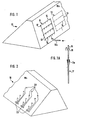
- 1 in FIG. 1 is a dam, on one side 10a, generally the so-called air side (Land side), a gas injection device is provided.
- the gas injection device consists of a first unit 11 and a second unit 12.
- the unit 11 has an essentially rectangular tubular frame, consisting of two vertical tubes 13 and four horizontal tubes 14.
- the vertical tubes 13 are at their ends closed. With 13a a gas connection is designated.
- the horizontal tubes 14 open into the tubes 13, i.e.
- the further unit 12 corresponds essentially to the unit 11. Further units (not shown) can be provided which have rollers by means of which they can be moved on the unit 11, for which purpose the tops of the vertical tubes 13 of the unit 11 are rail-like are trained. This results in an arrangement in the manner of a pull-out ladder.
- the "pull-out ladder" can consist of several such units, depending on the height of the dam.
- the device 11 has a number of sixteen injection tubes 17 made of light metal with a length of 0.5 m, which are distributed equally between the four horizontal tubes 14.
- the device 11 has a length and a height of 3 m each. Another unit can extend the height up to 6 m.
- a separate, rigid frame which can optionally be telescopically extended, on which frame one or more units 11 or 12 are then arranged such that they can be rolled.
- the use of a separate frame provides the advantage that it can also serve as a ladder for the operators when crossbars are attached.
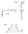
- the injection tubes 17 are pushed into the dam or inserted into prepared boreholes, the cones 17a serving as a seal. Then carbon dioxide or another measuring gas under low pressure is supplied to the devices 11 and 12, namely by connecting the measuring gas source 18 (FIG. 2B) to the gas connection 13a or a comparable connection of the device 12.
- a tank with liquid can be used as the measuring gas source
- Carbon dioxide with evaporator, carbon dioxide pressure bottles or pressure bottles or containers with methane, propane or sulfur dioxide can be used.
- Fig. 2 shows the opposite side 10b of the dam 10, generally the water side of the dam, on which the measuring device is provided.
- the measuring device consists of a plurality of measuring probes 20, each of which is connected according to FIG. 2A via a hose 21 and a solenoid valve 22 to a pipe 23, which is optionally equipped with a vacuum pump 24 or with a gas measuring device 25, preferably for C0 2 , connected is.
- each measuring probe 20 is formed by a tube which is perforated in its front region and has a sealing cone 20a in its rear region.
- the measuring probes 20 have a length of 20 cm and 10 probes 20 each form a measuring unit, the individual tubes 21 being combined to form a tube bundle.
- the perforation holes of the measuring probes 20 are expediently arranged in a spiral all around.
- the measuring probes 20 are pressed or hammered into the cover or insulating layer of the dam 10 or inserted into prefabricated boreholes.
- the distribution of the measuring probes 20 should be as uniform as possible; the number of measuring probes 20 used depends on the particular circumstances, the "resolution" of the resulting image being better, of course, the closer the measuring probes are inserted.
- the entire hose system with the probes connected to it are flushed with air and then evacuated. This facilitates gas entry into the probes and the further transport of the measurement gas into the measuring devices 25.
- the gas analyzes are called up individually by the probes, ie the individual solenoid valves 22 are opened in sequence and closed again.
- the analysis result is expediently displayed digitally.
- the measuring apparatus is provided with a strong diaphragm pump (not shown) which is so powerful that it can transport the gas received in the probes 20 via the hose lines to the measuring instruments 25.
- the measurement of the gas concentrations of C0 2 , methane and propane by the measuring devices 25 is expediently carried out on the principle of heat. Appropriate devices are available on the market. There are also various other measurement systems for sulfur dioxide.
- the output signals of the measuring devices 25 are expediently fed to a display device and / or a printing unit, in particular one with a graphic representation, whereby a kind of X-ray image of the dam structures is obtained and the evaluation is facilitated.
- the individual hose lengths can be reduced to Can be enlarged 7 times. This results in a total of 70 measuring hoses, which are combined in the lower part to form a hose bundle. With a pumping and analysis time of 20 seconds each, a total of about 24 minutes. required to carry out all measurements on a hose strand. If the measuring length of a dam exceeds 70 m, another measuring unit 70 m long can be used as the second measuring system. With a gas injection width of 3 m on the injection side, the width of the measuring probe system on the receiving side must be about 6 m due to the side scattering effects of the gas. A total of three hose systems are required for the measurement of a 6 m wide section, which, as stated above, can be designed up to 70 m. Every hose system requires a measuring apparatus and an operator.
- the number of measuring points is reduced accordingly.
- interconnecting the three hose systems for the 6 m wide measuring front one can work with one measuring apparatus and with one operator.
- the lateral displacement of the injection and measuring systems is expediently carried out on prepared, horizontally laid light metal rails.
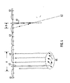
- FIG. 3 denotes a dam, in the sealing body 31 of which a control passage 32 runs parallel to the longitudinal axis of the dam.
- injection bores 33 are now drilled into the dam subsurface according to the invention, namely vertically or at an angle.
- the boreholes 33 can be partially or completely cased, in the latter case openings at the bottom of the borehole for the injection gas to be provided in the pipe wall.
- at least one measuring bore 34 is provided for receiving the injection gases, which preferably extends vertically and is piped in its upper region.
- the injection bores 33 and the measuring bores 34 serve to check the dam subsoil in the manner described below.
- a barrier layer for example a cement injection, is shown at 35 in FIG.
- an injection bore 36 which is partially piped, and measuring probes 37 mounted on the surface of the earth are used.
- a measuring probe 37 has a sealing cone 37a and is connected to a hose line 38 with a shut-off valve 39 - not shown - Measuring device connected. The measuring probe 37 is inserted into a prepared bore 40.
- the inspection of the dam subsoil is therefore carried out in practice with the aid of one or more injection bores 33 or 36 which are driven vertically or obliquely to a depth of 100 m into the geological subsoil.
- These bores 33 can also be carried out from the inspection passages 32 of the earth or stone dam 30 after completion of the construction work.
- the gases introduced into the cased or uncased bores 33 under pressure preferably carbon dioxide gases or also methane, propane or sulfur dioxide, spread more or less quickly and far underground depending on the permeability of the geological layers, partly also in solution in the groundwater.
- the spread of these gases in depth is detected by the measuring bores 34, the depths of which essentially correspond to those of the injection bores 33.
- the spread of the injected gases is not only horizontal, but also to a much greater extent towards the surface of the earth.
- additional shallow measuring holes 37 By making additional shallow measuring holes 37 to 0.8 m deep, it is possible to detect the spread and speed of gas displacement in the subsurface, even on the surface.
- the injected gas flows into the uncased lower part of the measuring boreholes, which were previously evacuated.
- the gas is collected in the piped part and fed to a measuring device for measurement via the shortest possible plastic hoses, for example in the manner described in the first exemplary embodiment.
- a measuring device for measurement via the shortest possible plastic hoses, for example in the manner described in the first exemplary embodiment.
- Additional surface measuring probes 37 are preferably also provided.
- the gases supplied through the injection bore 36 are prevented from spreading further horizontally in the subsurface and therefore flow after a short period of time towards the surface of the earth, where these gases can then be collected and measured. Only when the barrier layer 35 is interrupted or inadequately tight will a portion of the gases be able to continue flowing unhindered and accordingly only reach the surface after the barrier layer 35. An interruption of the barrier layer 35 is therefore noticeable in that in the interruption area that in front of the barrier layer 35 measuring probes 37 absorb significantly less gas than measuring probes of an uninterrupted, dense area of the barrier layer 35. Of course, it is also possible to place further flat measuring probes behind the barrier layer 35 and behind the dam 30 on the air side, which then through the barrier layer 35 measure gas that has passed through.
- FIG. 4 A third exemplary embodiment of the invention, which relates to the detection and location of underground cavities and tectonic disturbances of the subsurface, is explained below with reference to FIG. 4.
- 40 is an underground cavity
- 41 is a tectonic disturbance.
- an injection bore 42 leads vertically down into the cavity 40, and a large number of flat measuring probes 43 are arranged on the surface of the earth.
- Underground voids are created by geological processes or by mining work.
- the geologically determined cavities are sinkholes and caves. Cavities caused by mining are wells, boreholes, shafts, tunnels and device lines for the extraction of raw materials.
- the method of the invention can now be used to locate such underground cavities of unknown extent and extension. Under normal rock mechanics conditions, a subsidence cone with directed and widened microstructures forms above collapsed cavities. These structures run towards the hollow body and cause a greater permeability between the underground cavity and the surface of the earth.
- gases can spread along such secondary structural zones. For this purpose, carbon dioxide gas or other suitable gases are injected into the cavity 40 through the injection bore 42.
- the gas which is introduced under pressure and partly also soluble in water, spreads out laterally in the cavity 40, and with increasing pressure, gases diffuse upward over the loosened structural zones, where they are measured by the flat measuring probes 43.
- the gas-filled cavity 40 is thus, so to speak, using the gases on the surface of the earth.
- the measuring probes 43 in area A of FIG. 4 will thus take up gas, whereas the remaining measuring probes 43 remain gas-free.
- the design and arrangement of the flat measuring probes 43 correspond to the measuring probes 37 in FIG. 3A.
- the practical way of locating underground cavities 40 is based on a preliminary investigation of the natural distribution of soil gas above a suspected cavity.
- the natural gas concentration associated with the formation of cavities gives raw reference values in the loosened structure of the rock about the extent of the cavity and thus a reference point for the preparation of one or more injection holes 42.
- the second step for the more precise location of underground cavities 40 is then carried out with the help of one or several holes made.
- the landing point of the bore 42 is, if possible, the cavity 40 itself or the mountains directly affected by it, which is connected to the cavity 40 via the loosened structure.
- the bore 42 is provisionally piped to just above the loose zones.
- the measurement gases are injected under pressure into the cavity 40 above the head of the piping. During and after the injection, the bottom gas measurements are carried out to determine the gas contents in areas of increased permeability.
- a particular advantage of the method of the invention is that, particularly when carbon dioxide is selected as the injection gas, no permanent and harmful effects on rocks, soils and buildings are caused, because most of the injected gas migrates quickly to the surface of the earth and only a very small part of the gas , about 0.1%, is consumed in the groundwater for carbonation.
- Carbon dioxide has the further advantage that it can be detected quickly and precisely quantitatively using simple measuring devices.
- the method can be used to locate cavities that are at depths of up to 200 m and deeper.
- the other gases mentioned also have no harmful effects, which is related to the high levels of dilution in the layers of earth and rock.
- the method just described can also be used to detect tectonic disturbances in the subsurface. If the normal storage of a mountain range is disturbed by fractures (upward and downward movements, active fissures), artificial mass accumulations, such as the construction of dams and buildings or the build-up of dams, can increase the movement processes of the tectonic fractures. On the other hand, such breaks can also be the cause of uncontrolled groundwater flows.
- the injection bore 42 extends from a few meters to can be over 100 m deep, test gases are pressed in under pressure, which spread out laterally in porous layers of the subsurface.
- test gases are pressed in under pressure, which spread out laterally in porous layers of the subsurface.
- the tectonic disturbance 41 forms a kind of drainage for the artificially introduced gases.
- the gases are measured in the same way as when locating cavities. In this case, the flat measuring probes in area B detect gas, while the measuring probes remain essentially gas-free outside this area.
- radioactive gases are particularly suitable as measurement gases, because even with the smallest amounts of gas, exact measurements can be carried out using appropriate detectors; preferably one will choose gases that are easy to activate and - for safety reasons - ensure the shortest possible half-life. Otherwise, with low permeability, gases with the lowest possible density will be chosen, for example helium, i.e. gases with great penetration ability.
Landscapes
- Life Sciences & Earth Sciences (AREA)
- Engineering & Computer Science (AREA)
- Mining & Mineral Resources (AREA)
- Geology (AREA)
- Physics & Mathematics (AREA)
- General Life Sciences & Earth Sciences (AREA)
- Chemical & Material Sciences (AREA)
- Paleontology (AREA)
- Environmental & Geological Engineering (AREA)
- Geochemistry & Mineralogy (AREA)
- Geophysics (AREA)
- Analytical Chemistry (AREA)
- Soil Sciences (AREA)
- Fluid Mechanics (AREA)
- Civil Engineering (AREA)
- General Engineering & Computer Science (AREA)
- Structural Engineering (AREA)
- Investigation Of Foundation Soil And Reinforcement Of Foundation Soil By Compacting Or Drainage (AREA)
- Geophysics And Detection Of Objects (AREA)
- Analysing Materials By The Use Of Radiation (AREA)
- Sampling And Sample Adjustment (AREA)
- Superconductors And Manufacturing Methods Therefor (AREA)
Claims (18)
Priority Applications (6)
| Application Number | Priority Date | Filing Date | Title |
|---|---|---|---|
| EP82109653A EP0105967B1 (fr) | 1982-10-19 | 1982-10-19 | Méthode et dispositif pour l'investigation de la structure et de la perméabilité dans les domaines des sols et des rochers |
| DE8282109653T DE3271679D1 (en) | 1982-10-19 | 1982-10-19 | Method and apparatus for the investigation of the structure and permeability of soil and rock formations |
| AT82109653T ATE20366T1 (de) | 1982-10-19 | 1982-10-19 | Verfahren und vorrichtung zum untersuchen der struktur und der durchlaessigkeit von erd- und gesteinsbereichen. |
| CA000439208A CA1203401A (fr) | 1982-10-19 | 1983-10-18 | Methode et dispositif d'investigation de la structure et de la porosite du sous-sol fait de terre et de couches rocheuses |
| AU20284/83A AU570221B2 (en) | 1982-10-19 | 1983-10-18 | Investigating the structure and porosity of earth regions |
| US06/543,434 US4537062A (en) | 1982-10-19 | 1983-10-19 | Method and apparatus for investigating the structure and porosity of earth and stony regions |
Applications Claiming Priority (1)
| Application Number | Priority Date | Filing Date | Title |
|---|---|---|---|
| EP82109653A EP0105967B1 (fr) | 1982-10-19 | 1982-10-19 | Méthode et dispositif pour l'investigation de la structure et de la perméabilité dans les domaines des sols et des rochers |
Publications (2)
| Publication Number | Publication Date |
|---|---|
| EP0105967A1 EP0105967A1 (fr) | 1984-04-25 |
| EP0105967B1 true EP0105967B1 (fr) | 1986-06-11 |
Family
ID=8189291
Family Applications (1)
| Application Number | Title | Priority Date | Filing Date |
|---|---|---|---|
| EP82109653A Expired EP0105967B1 (fr) | 1982-10-19 | 1982-10-19 | Méthode et dispositif pour l'investigation de la structure et de la perméabilité dans les domaines des sols et des rochers |
Country Status (6)
| Country | Link |
|---|---|
| US (1) | US4537062A (fr) |
| EP (1) | EP0105967B1 (fr) |
| AT (1) | ATE20366T1 (fr) |
| AU (1) | AU570221B2 (fr) |
| CA (1) | CA1203401A (fr) |
| DE (1) | DE3271679D1 (fr) |
Families Citing this family (12)
| Publication number | Priority date | Publication date | Assignee | Title |
|---|---|---|---|---|
| RU2180743C2 (ru) * | 1999-10-01 | 2002-03-20 | Ковровская государственная технологическая академия | Способ определения активной пористости материалов |
| US7244965B2 (en) * | 2002-09-04 | 2007-07-17 | Cree Inc, | Power surface mount light emitting die package |
| US7686401B1 (en) | 2008-10-09 | 2010-03-30 | J.I. Enterprises, Inc. | Method for sub-glacial mineral reconnaissance and recovery |
| US8065087B2 (en) * | 2009-01-30 | 2011-11-22 | Gyrodata, Incorporated | Reducing error contributions to gyroscopic measurements from a wellbore survey system |
| US20120134749A1 (en) * | 2010-11-15 | 2012-05-31 | Thomas Darrah | Using noble gas geochemistry to evaluate fluid migration in hydrocarbon bearing black shales |
| JP6391010B2 (ja) * | 2014-12-18 | 2018-09-19 | 清水建設株式会社 | トンネル切羽前方の透水特性の評価方法および評価システム |
| CN105181554A (zh) * | 2015-09-18 | 2015-12-23 | 中国矿业大学(北京) | 一种应用灌浆层的横向接缝的防水测试方法 |
| CN109946370A (zh) * | 2019-02-19 | 2019-06-28 | 中南大学 | 一种基于磁场测量的堤坝渗漏通道检测方法及其装置 |
| CN114295529B (zh) * | 2022-01-05 | 2023-07-25 | 国家能源集团新疆能源有限责任公司 | 一种人工扰动后岩体内部裂隙发育情况测定方法及系统 |
| CN116357392B (zh) * | 2023-04-28 | 2025-12-23 | 太原理工大学 | 一种废弃大巷中储碳空间充填重构-co2封存的方法 |
| CN118225524B (zh) * | 2024-02-20 | 2024-09-24 | 中国矿业大学 | 废弃矿井遗煤空隙-裂隙-孔隙介质重构装置及重构方法 |
| CN119207059A (zh) * | 2024-11-27 | 2024-12-27 | 安徽建筑大学 | 一种堤坝裂缝监测预警系统及方法 |
Family Cites Families (11)
| Publication number | Priority date | Publication date | Assignee | Title |
|---|---|---|---|---|
| US2318689A (en) * | 1943-05-11 | Tracing gas through underground | ||
| US2414913A (en) * | 1942-05-18 | 1947-01-28 | Standard Oil Dev Co | Soil gas prospecting |
| US2429577A (en) * | 1944-11-22 | 1947-10-21 | Continental Oil Co | Method for determining fluid conductance of earth layers |
| US2589219A (en) * | 1947-04-24 | 1952-03-18 | Pure Oil Co | Method of studying earth formations employing acetylene as a tracer gas |
| US3010023A (en) * | 1957-11-12 | 1961-11-21 | Texaco Inc | Gas injectivity profile logging |
| US3106089A (en) * | 1962-01-08 | 1963-10-08 | Scott Corp | Method and apparatus for locating leaks |
| US3381523A (en) * | 1965-03-03 | 1968-05-07 | Henry D. Nettles | Method and apparatus for supplying gas under pressure |
| US3690167A (en) * | 1970-01-14 | 1972-09-12 | Shell Oil Co | Method for determining the reservoir properties of a formation |
| US3889521A (en) * | 1974-05-15 | 1975-06-17 | Nat Steel Corp | Static gas pressure measuring device |
| US4052885A (en) * | 1976-08-24 | 1977-10-11 | The United States Of America As Represented By The United States Energy Research And Development Administration | Portable device and method for determining permeability characteristics of earth formations |
| CA1131463A (fr) * | 1980-08-01 | 1982-09-14 | Susan A. De Korompay | Methode de detection de failles |
-
1982
- 1982-10-19 AT AT82109653T patent/ATE20366T1/de not_active IP Right Cessation
- 1982-10-19 EP EP82109653A patent/EP0105967B1/fr not_active Expired
- 1982-10-19 DE DE8282109653T patent/DE3271679D1/de not_active Expired
-
1983
- 1983-10-18 CA CA000439208A patent/CA1203401A/fr not_active Expired
- 1983-10-18 AU AU20284/83A patent/AU570221B2/en not_active Ceased
- 1983-10-19 US US06/543,434 patent/US4537062A/en not_active Expired - Fee Related
Also Published As
| Publication number | Publication date |
|---|---|
| EP0105967A1 (fr) | 1984-04-25 |
| DE3271679D1 (en) | 1986-07-17 |
| ATE20366T1 (de) | 1986-06-15 |
| US4537062A (en) | 1985-08-27 |
| AU2028483A (en) | 1984-05-03 |
| CA1203401A (fr) | 1986-04-22 |
| AU570221B2 (en) | 1988-03-10 |
Similar Documents
| Publication | Publication Date | Title |
|---|---|---|
| EP0105967B1 (fr) | Méthode et dispositif pour l'investigation de la structure et de la perméabilité dans les domaines des sols et des rochers | |
| Seed et al. | The failure of Teton dam | |
| Stark et al. | Soil inclusions in jet grout columns | |
| DE2712869C2 (de) | Verfahren zum Vermeiden von Wassereinbrüchen in untertägige Hohlräume | |
| Marte et al. | Creeping large‐scale landslides–Characterisation and assessment of safety | |
| Kimpritis | The control of column diameter and strength in Jet Grouting processes and the influence of ground conditions | |
| Holzer et al. | Semmering Base Tunnel–Tunnelling in challenging geotechnical and geological conditions in major fault zones | |
| DE4446008C2 (de) | Verfahren und Anlage für die Verdichtung eines Bodens mit Hilfe von Sprengladungen | |
| DE102015200530B4 (de) | Verfahren zur Bewertung von Düsenstrahlsäulen | |
| DE19837055C2 (de) | Injektionsvorrichtung und Verfahren zum Abdichten von im Erdreich befindlichen Bauteilen | |
| Kielbassa et al. | Karst investigation and treatment measures for the high‐speed track on the Swabian Jura/Karsterkundungs‐und Sanierungsmaßnahmen für den Hochgeschwindigkeitsfahrweg auf der Schwäbischen Alb | |
| DE19807060A1 (de) | Verfahren und Vorrichtung zur Einbringung eines fließfähigen Mittels in den Erdboden | |
| DE3821823A1 (de) | Verfahren zur ermittlung der luftdurchlaessigkeit von wasserfuehrenden boeden sowie anlage und vorrichtungen zu dessen durchfuehrung | |
| Marte et al. | Construction of a snow retention basin in an Alpine sagging mass/Errichtung eines Beschneiungsteiches in einer alpinen Sackungsmasse | |
| Knight et al. | Seepage remediation and karst foundation treatment at Clearwater Dam, Piedmont, Missouri | |
| DE4446028C2 (de) | Verfahren und Anlage zum Stabilisieren eines Bodens mit Hilfe von Injektionen | |
| Vukotić | SOIL IMPROVEMENT BY JET GROUTING FOR THE CONSTRUCTION OF THE ACCESS TO THE BARCELONA AIRPORT APPLICATION OF THE RECENT TECHNOLOGIES | |
| CH701566A1 (de) | Verfahren zur Früherfassung von Baugrundsetzungen beim Tunnelbau. | |
| Schachinger et al. | Results from the Untersammelsdorf test field for the planning of tunnelling work | |
| Gerstner et al. | Geological basics, geotechnical design and lining of the new headrace system for the Rodundwerk I | |
| Schmidt et al. | Geotechnical Challenges at the Town Hall–Construction Phase U2/22 | |
| Kwon et al. | Clogging theory-based real time grouting management system for underwater tunnel | |
| DE102023001571A1 (de) | Verfahren und Anlage zur Radon-Sanierung von Gebäuden | |
| DE19709079C2 (de) | Verfahren zur Verringerung der Verflüssigungsneigung locker gelagerter, wassergesättigter Kippenmischböden | |
| Schwalt et al. | Storage sites for tunnel excavation material–challenges and approach using the Gotthard and Ceneri Base Tunnels as examples: Ablagerungen von Tunnelausbruchmaterial–Herausforderungen und Vorgehen am Beispiel Gotthard‐und Ceneri‐Basistunnel |
Legal Events
| Date | Code | Title | Description |
|---|---|---|---|
| PUAI | Public reference made under article 153(3) epc to a published international application that has entered the european phase |
Free format text: ORIGINAL CODE: 0009012 |
|
| 17P | Request for examination filed |
Effective date: 19831011 |
|
| AK | Designated contracting states |
Designated state(s): AT BE CH DE FR GB IT LI NL |
|
| GRAA | (expected) grant |
Free format text: ORIGINAL CODE: 0009210 |
|
| ITF | It: translation for a ep patent filed | ||
| AK | Designated contracting states |
Kind code of ref document: B1 Designated state(s): AT BE CH DE FR GB IT LI NL |
|
| REF | Corresponds to: |
Ref document number: 20366 Country of ref document: AT Date of ref document: 19860615 Kind code of ref document: T |
|
| REF | Corresponds to: |
Ref document number: 3271679 Country of ref document: DE Date of ref document: 19860717 |
|
| ET | Fr: translation filed | ||
| RAP2 | Party data changed (patent owner data changed or rights of a patent transferred) |
Owner name: KOHLENSAEURE-WERKE RUD. BUSE GMBH & CO. |
|
| NLT2 | Nl: modifications (of names), taken from the european patent patent bulletin |
Owner name: KOHLENSAEURE-WERKE RUD. BUSE GMBH & CO. TE BAD HOE |
|
| BECN | Be: change of holder's name |
Effective date: 19860611 |
|
| PLBE | No opposition filed within time limit |
Free format text: ORIGINAL CODE: 0009261 |
|
| STAA | Information on the status of an ep patent application or granted ep patent |
Free format text: STATUS: NO OPPOSITION FILED WITHIN TIME LIMIT |
|
| 26N | No opposition filed | ||
| ITTA | It: last paid annual fee | ||
| REG | Reference to a national code |
Ref country code: CH Ref legal event code: PUE Owner name: KOHLENSAEURE-WERKE RUD. BUSE GMBH & CO. TRANSFER- |
|
| ITPR | It: changes in ownership of a european patent |
Owner name: CESSIONE;HEIDELBERGER BAUSTOFFTECHNIK GMBH |
|
| REG | Reference to a national code |
Ref country code: FR Ref legal event code: TP |
|
| NLS | Nl: assignments of ep-patents |
Owner name: HEIDELBERGER BAUSTOFFTECHNIK GMBH TE LEIMEN, BONDS |
|
| REG | Reference to a national code |
Ref country code: GB Ref legal event code: 732E |
|
| PGFP | Annual fee paid to national office [announced via postgrant information from national office to epo] |
Ref country code: GB Payment date: 19960930 Year of fee payment: 15 |
|
| PGFP | Annual fee paid to national office [announced via postgrant information from national office to epo] |
Ref country code: FR Payment date: 19961016 Year of fee payment: 15 |
|
| PGFP | Annual fee paid to national office [announced via postgrant information from national office to epo] |
Ref country code: BE Payment date: 19961021 Year of fee payment: 15 Ref country code: AT Payment date: 19961021 Year of fee payment: 15 |
|
| PGFP | Annual fee paid to national office [announced via postgrant information from national office to epo] |
Ref country code: CH Payment date: 19961024 Year of fee payment: 15 |
|
| PGFP | Annual fee paid to national office [announced via postgrant information from national office to epo] |
Ref country code: NL Payment date: 19961029 Year of fee payment: 15 |
|
| PGFP | Annual fee paid to national office [announced via postgrant information from national office to epo] |
Ref country code: DE Payment date: 19961221 Year of fee payment: 15 |
|
| PG25 | Lapsed in a contracting state [announced via postgrant information from national office to epo] |
Ref country code: GB Free format text: LAPSE BECAUSE OF NON-PAYMENT OF DUE FEES Effective date: 19971019 Ref country code: AT Free format text: LAPSE BECAUSE OF NON-PAYMENT OF DUE FEES Effective date: 19971019 |
|
| PG25 | Lapsed in a contracting state [announced via postgrant information from national office to epo] |
Ref country code: LI Free format text: LAPSE BECAUSE OF NON-PAYMENT OF DUE FEES Effective date: 19971031 Ref country code: FR Free format text: THE PATENT HAS BEEN ANNULLED BY A DECISION OF A NATIONAL AUTHORITY Effective date: 19971031 Ref country code: CH Free format text: LAPSE BECAUSE OF NON-PAYMENT OF DUE FEES Effective date: 19971031 Ref country code: BE Free format text: LAPSE BECAUSE OF NON-PAYMENT OF DUE FEES Effective date: 19971031 |
|
| BERE | Be: lapsed |
Owner name: HEIDELBERGER BAUSTOFFTECHNIK G.M.B.H. Effective date: 19971031 |
|
| PG25 | Lapsed in a contracting state [announced via postgrant information from national office to epo] |
Ref country code: NL Free format text: LAPSE BECAUSE OF NON-PAYMENT OF DUE FEES Effective date: 19980501 |
|
| GBPC | Gb: european patent ceased through non-payment of renewal fee |
Effective date: 19971019 |
|
| REG | Reference to a national code |
Ref country code: CH Ref legal event code: PL |
|
| NLV4 | Nl: lapsed or anulled due to non-payment of the annual fee |
Effective date: 19980501 |
|
| PG25 | Lapsed in a contracting state [announced via postgrant information from national office to epo] |
Ref country code: DE Free format text: LAPSE BECAUSE OF NON-PAYMENT OF DUE FEES Effective date: 19980701 |
|
| REG | Reference to a national code |
Ref country code: FR Ref legal event code: ST |