EP0106186A2 - Machine d'outillage à main, particulièrement perçeuse - Google Patents
Machine d'outillage à main, particulièrement perçeuse Download PDFInfo
- Publication number
- EP0106186A2 EP0106186A2 EP83109253A EP83109253A EP0106186A2 EP 0106186 A2 EP0106186 A2 EP 0106186A2 EP 83109253 A EP83109253 A EP 83109253A EP 83109253 A EP83109253 A EP 83109253A EP 0106186 A2 EP0106186 A2 EP 0106186A2
- Authority
- EP
- European Patent Office
- Prior art keywords
- tool according
- hand tool
- drill
- scanning device
- button
- Prior art date
- Legal status (The legal status is an assumption and is not a legal conclusion. Google has not performed a legal analysis and makes no representation as to the accuracy of the status listed.)
- Granted
Links
Images




Classifications
-
- B—PERFORMING OPERATIONS; TRANSPORTING
- B23—MACHINE TOOLS; METAL-WORKING NOT OTHERWISE PROVIDED FOR
- B23B—TURNING; BORING
- B23B45/00—Hand-held or like portable drilling machines, e.g. drill guns; Equipment therefor
- B23B45/02—Hand-held or like portable drilling machines, e.g. drill guns; Equipment therefor driven by electric power
-
- G—PHYSICS
- G01—MEASURING; TESTING
- G01B—MEASURING LENGTH, THICKNESS OR SIMILAR LINEAR DIMENSIONS; MEASURING ANGLES; MEASURING AREAS; MEASURING IRREGULARITIES OF SURFACES OR CONTOURS
- G01B5/00—Measuring arrangements characterised by the use of mechanical techniques
- G01B5/08—Measuring arrangements characterised by the use of mechanical techniques for measuring diameters
-
- G—PHYSICS
- G01—MEASURING; TESTING
- G01B—MEASURING LENGTH, THICKNESS OR SIMILAR LINEAR DIMENSIONS; MEASURING ANGLES; MEASURING AREAS; MEASURING IRREGULARITIES OF SURFACES OR CONTOURS
- G01B7/00—Measuring arrangements characterised by the use of electric or magnetic techniques
- G01B7/12—Measuring arrangements characterised by the use of electric or magnetic techniques for measuring diameters
-
- Y—GENERAL TAGGING OF NEW TECHNOLOGICAL DEVELOPMENTS; GENERAL TAGGING OF CROSS-SECTIONAL TECHNOLOGIES SPANNING OVER SEVERAL SECTIONS OF THE IPC; TECHNICAL SUBJECTS COVERED BY FORMER USPC CROSS-REFERENCE ART COLLECTIONS [XRACs] AND DIGESTS
- Y10—TECHNICAL SUBJECTS COVERED BY FORMER USPC
- Y10T—TECHNICAL SUBJECTS COVERED BY FORMER US CLASSIFICATION
- Y10T408/00—Cutting by use of rotating axially moving tool
- Y10T408/08—Cutting by use of rotating axially moving tool with means to regulate operation by use of templet, tape, card, or other replaceable information supply
-
- Y—GENERAL TAGGING OF NEW TECHNOLOGICAL DEVELOPMENTS; GENERAL TAGGING OF CROSS-SECTIONAL TECHNOLOGIES SPANNING OVER SEVERAL SECTIONS OF THE IPC; TECHNICAL SUBJECTS COVERED BY FORMER USPC CROSS-REFERENCE ART COLLECTIONS [XRACs] AND DIGESTS
- Y10—TECHNICAL SUBJECTS COVERED BY FORMER USPC
- Y10T—TECHNICAL SUBJECTS COVERED BY FORMER US CLASSIFICATION
- Y10T408/00—Cutting by use of rotating axially moving tool
- Y10T408/16—Cutting by use of rotating axially moving tool with control means energized in response to activator stimulated by condition sensor
- Y10T408/165—Cutting by use of rotating axially moving tool with control means energized in response to activator stimulated by condition sensor to control Tool rotation
Definitions
- the invention is based on a hand tool according to the type of the main claim.
- a hand-held power tool is already known from European patent application 00810465.
- the position of the jaws of a drill chuck is determined by a button, which passes on the sensed value to a control device for the motor of the hand tool.
- the speed of this motor is controlled in accordance with the shaft diameter of the drill shaft clamped in the chuck that is indirectly determined.
- the inserted shank diameter does not correspond to the working diameter of the drill. Incorrect settings are inevitable here.
- the specified hand-held power tool with the described control device is also not suitable for giving the person working with it information about the diameter of the clamped drill.
- the hand tool according to the invention with the characterizing features of the main claim has the advantage that the working diameter of the tool - hi-er the drill - can be entered and displayed in the hand tool before clamping.
- the actual working diameter of the tool can be determined quickly by the scanning device separated from the tool clamping element. The operator is informed of the working diameter by the display of the button result. The time-consuming clamping and possibly necessary unclamping of the tool is avoided.
- the hand-held power tool has a button with a scale and a reference mark, which allow the position of the button to be read, and that it has an electronic distance meter assigned to the button, the output values of which can be evaluated for motor control.
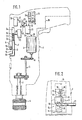
- FIG. 1 shows a first exemplary embodiment using a hand drill with a feeler slide and display, storage and control devices assigned to it
- FIG. 2 shows a partial view of FIG. 1
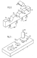
- FIG. 3 shows a second exemplary embodiment of a scanning device such as that according to the invention in a Hand machine tool may be incorporated in a perspective view
- Figure 4 shows a further embodiment of a scanning device in a perspective D working position
- Figure 5 is a further embodiment of a scanning device which does not use springs, in a perspective view
- FIG. 7 shows another exemplary embodiment for group-like detection as in FIG.
- FIG. 8 shows a probe device for grouping in groups by means of a gauge with a conical funnel, in a perspective view
- FIG. 9 a last embodiment for the group-wise detection of tool diameters by means of a gauge with a wedge-shaped recess, in a perspective view
- FIG. 10 shows an embodiment according to an inductive measuring method for determining the tool diameter by HF Coupling
- Figure 11 shows another embodiment for inductive determination of the tool diameter by damping
- Figure 12 shows an embodiment similar to Figure 11 with a modified structure.
- a hand drill 1 In a first exemplary embodiment according to FIGS. 1 and 2, a hand drill 1 is shown. It comprises a motor 2 and a drilling spindle 3 with a drill chuck 4. The motor 2 is connected to the drilling spindle 3 via a countershaft 5 which is driven by a motor pinion 6.
- a scanning device 7 built into this hand drill 1 essentially consists of a stop piece 8 designed as a magnifying glass, a push-button slide 9, a coupling 10 and a measured value transmitter memory 11.
- the push-button slide 9 is under the Effect of a compression spring 12, which finds its abutment on a tab 13 of the housing of the hand drill 1.
- the housing of the hand drill 1 also forms a slide guide 14, which is open to the outside at 15.
- the coupling 10 engages in a slot 16 of the slide switch 9 and is guided with its other end inside the measured value transmitter memory 11.
- the compression spring 12 lies within a recess 17 in the slide valve 9.
- the end of the slide valve 9 facing away from the compression spring 12 is angled and designed as measuring jaws 18.
- This measuring jaw 18 protrudes through the opening 15 in the housing of the hand drill 1 to the outside. It is placed opposite the stop piece 8, which has a measuring surface 19.
- the slide switch 9 On its outwardly facing surface, the slide switch 9 carries a scale 20.
- This scale 20 is assigned a vernier 21, which is attached to the lower surface of the stop piece 8 facing the slide switch 9.
- the compression spring 12 always seeks to move the slide switch 9 into its zero position, in which the measuring surface of the measuring jaw 18 bears against the measuring surface 19 of the stop piece 8.
- the slide valve 9 is retracted into its other end position, so that the distance between the measuring jaw 18 and the measuring surface 19 corresponds to the possible measuring range of the slide valve 9.
- a drill 22 is inserted between the measuring jaws 18 and the measuring surface 19 such that the cutting edges of the drill 22 determine the distance between the measuring jaw 18 and the measuring surface 19 when the push-button slide 9 is released.
- a distributor 23, whose input 24 is connected to the output 25 of the measured value transmitter memory 11, is arranged downstream of the measured value transmitter memory 11.
- An output 26 of the distributor 23 is connected to an input 27 of a display device 28.
- a second output 29 of the distributor 23 is connected to an input 30 of a control unit 31, which has a whiten input 32 and an output 33 has.
- the further input 32 is connected to an output 34 of an input device 35.
- the input device 35 has a plurality of input buttons 36 with which a value for the material of the workpiece to be machined can be keyed in.
- the output 33 of the control unit 31 is connected to an input 37 of the motor 2.
- the electrical connection from a power supply line to the motor 2 via a pusher switch is indicated by a dashed line 38. It corresponds to the conventional.
- the drill 22 is inserted between the measuring jaws 18 and the measuring surface 19 in the manner shown.
- the value corresponding to the working diameter of the drill 22 can be read off on the scale 20 by means of the.
- the position of the slide switch 9 reached in this way is transmitted via the coupling 10 to the measured value transmitter memory 11, which transmits a corresponding analog or digital value to the distributor 23.
- This value comes from the distributor 23 to the display device 28, on which the same measured value can be read digitally.
- the value passed on from the distributor 23 to the control unit 31, together with the value that is fed from the input device 35 to the control unit 31, produces an output variable that optimally adjusts the motor 2.
- the loupe-shaped design of the stop piece 8 makes it easier to read the position of the vernier 21 relative to the scale 20.
- the two displays of the scanned diameter can also be used alone.
- either the scale 20, the vernier 21 and the loupe-shaped design of the stop piece 8 or the display device 28 are saved.
- the scanning device 7 is replaced by a scanning device 39.
- a spindle 40 with a high helix 41.
- This spindle 40 is rotatably but not axially displaceably mounted.
- An inner tab of a spiral spring 43 engages in a slot 42 at the lower end of the spindle 40.
- a cable end 46 shown attacking on pin 45 symbolizes the ground connection of an electrical measuring section.
- a resistance track 48 is applied above the coil spring 43, on a bearing 47 for the spindle 40.
- the end of the resistance track 48 is connected to a cable end 49, which symbolizes the connection from the resistance track 48 to a measured value transmitter memory corresponding to the measured value transmitter memory 11.
- a contact tongue 50 which is fixedly connected to the spindle 40, rests on the resistance track 48. It can cover its entire length.
- a driver 51 is screwed onto the steep thread 41. It is movably joined in the direction of the longitudinal axis of the spindle 40 by sliding pieces 52 and 53, but is prevented from rotating about the longitudinal axis of this spindle 40. Above the steep thread 41, the spindle 40 passes through a housing-fixed disk 54, which has an opening 55 perpendicularly above the driver 51.
- a disk 56 Coaxial with this disk 54 is a disk 56 fixedly connected to the spindle 40 above this disk 54.
- This disk 56 has a wedge-shaped tapering line symmetrical to a circular arc around the longitudinal axis of the spindle 40 arranged opening 57, the line of symmetry running through the central axis of the opening 55 in the disc 5h.
- a nose 58 of the disk 56 and a stop 59 fixed to the housing determine the end position of the disk 56, and thus the spindle 40, which is desired by the action of the spiral spring 43. In this end position, the end of the opening 57 and the opening 55 overlap.
- a drill 22 guided through the openings 57 and 55 in the direction of the arrows 60 and 61 hits the surface of the driver 51 facing it. If pressure is exerted on the driver 51 with this drill 22, the latter rotates the spindle via the steep thread 41 40 against the action of the spiral spring 43 in the direction of arrow 62. This rotary movement is stopped as soon as the tapering opening 57 and the opening 55 clamp the drill 22.
- the contact tongue 50 has slid over the resistance track 48 and, after this rotary movement has ended, assumes a position determined by the diameter of the drill .22.
- the resistance value resulting from the piece of the resistance track 48 between the contact tongue 50 and the cable end 49 corresponds to the drill diameter. As shown in the exemplary embodiment according to FIGS. 1 and 2, it can be evaluated to display the drill diameter and to control the motor 2.
- FIG. 4 corresponds in principle to that according to FIG. 3.
- a bracket 63 fixed to the housing carries a flexible band 64.
- the free leg 65 of this bracket 63 has a circular opening 66. This is congruent with the end of a wedge-shaped tapering starting from a circle to an opening 67 which extends symmetrically in the direction of displacement of the band 64.
- Two pins 68 at an angle 63 engage in the longitudinal direction slots 69 of tape 64.
- a tension spring 70 always tries to hold the band 64 in its end position.
- a shaft mounted in the housing 71 supports a guide roller 72, over which the tape is guided bent through 90 0 64th
- the bent end 73 of the band 64 is firmly connected to a pivot plate 74. This in turn is mounted in a hinge 75 fixed to the housing.
- a resistance track 76 corresponds to the resistance track 48 according to FIG. 3, a contact tongue 77 of the contact tongue 50 according to FIG. 3.
- the rotary movement of the deflection roller 72 with the shaft 71 that is carried out is a measure of the drill diameter.
- the resistance sensed by the contact tongue 77 on the resistance track 76 represents this measure electrically.
- a shaft 80 is mounted in the housing of the hand drill 1.
- This shaft 80 carries a circular disk 81 and a semicircular disk 82.
- the disk 81 and the semicircular disk 82 lie close together.
- the back of the disk 81 facing away from the semicircular disk 82 carries a resistance track 83.
- a contact tongue 84 fixed at the end of the shaft 80, scans this resistance track 83.
- Both the disk 81 and the semicircular disk 82 carry two rollers 85 and 86 or 87 and 88. These rollers 85 to 88 are rotatably supported on pins 89.
- rollers 86 and 88 are arranged in the same way below the shaft 80.
- a wedge 90 is inserted between the rollers 86 and 88, the tip of which points downward.
- the rollers 86 and 88 thus moving closer together raise the wedge 90. If the end of the drill 22 presses on the wedge 90, the latter seeks to push the rollers 86 and 88 apart again. This is possible as long as there is clearance between the rollers 85 and 87 and the drill 22. If both rollers 85 and 87 lie firmly against the drill, the insertion movement of the drill 22 is ended.
- the device shown here does not require a spring to measure.
- the drill diameter is represented by the resistance track 83 tapped off from the contact tongue 84.
- the exemplary embodiments according to FIGS. 6 to 9 are used for the gradual detection of drill groups with different diameters within the group.
- a comb-like gauge 93 is attached to the housing of the hand drill 1.
- the gauge 93 has semicircular recesses 94 to 97. These semicircular recesses are graduated between a largest diameter and a smallest diameter.
- switch pins 98 to 101 At the bottom of the recesses 94 to 97 switch pins 98 to 101, all in the Electrical switches 102 can intervene in order to close these switches 102.
- a jig 103 is attached to the housing of the hand drill 1, in which cup-shaped recesses 104 to 107 are used instead of the recesses 94 to 97 according to the embodiment according to FIG.
- a drill 22 inserted in the direction of arrow 109 can touch a contact pin 108 if it has a sufficiently small diameter to be able to be inserted into the smallest possible cup-shaped recesses.
- the measurement must be carried out in the same way as in the embodiment according to FIG. 6.
- a jig 110 is arranged in the housing of the hand drill 1, which has a -conical recess 111.
- One half 112 of the gauge 110 is formed in one piece.
- the half 112 of the gauge 110 is separated from the other half of the gauge 110 by an insulation layer 113 in the axial direction of the conical recess 111.
- the second half of the gauge 110 is layered from four electrically conductive parts 114 to 117, each with insulation arranged between them layers 118 to 120.
- An electrical connection of a measuring section 121 is led to the one-piece half 112 of the gauge 110, while on the other hand such a connection is assigned to each of the parts 114 to 117.
- the part 114 is provided with a connection 122, the part 115 with a connection 123, the part 116 with a connection 124, and the part 117 with a connection 125.
- the connections 122 to 125 are connected to the measuring section 121 via resistors 126 to 129 of different values.
- the measuring circuit is closed from half 112 to one of the parts 114 to 117.
- signals can be taken directly digitally at connections 122 to 125.
- a gauge 130 which has a wedge-shaped recess 131.
- the teaching 130 is set up. from a one-piece half 132 and a half separated from it by an insulating layer 133 with layered parts 134 to 137, with interposed insulating layers 138 to 140.
- a drill 22 can be inserted in the direction of a part 139 either vertically or lying down. The measurement corresponds to that of FIG. 8.
- a carrier body 140 is introduced into the housing of the hand drill 1, which has a cylindrical cavity 141. On the outside, this carrier body 140 is divided into two winding spaces 142 and 143, in which two coils 144 and 145 are wrapped. The coil 145 is connected to an AC voltage source 146, while the coil 144 is connected to a measuring section 147. The RF coupling between the two coils 144 and 145, which can be determined by the measuring section 147, is a measure of the diameter of the inserted drill 22.
- a carrier body 148 is introduced into the housing of the hand drill 1. This has a recess 149 and carries a coil 150 on the outside.
- a control pin 151 is attached to the base of the recess 149 and can close a switch 152. With the switch 152, a supply voltage z. B. for the HF generator 157 to a memory. This always happens in the desired manner for a short time and only when the measurement signal is actually needed.
- a drill 22 inserted into the recess 149 changes the inductance or damping in the coil 150 and thus the measured value at the resistor 158.
- the extent of the change is a measure of its diameter.
- a carrier body 154 instead of the carrier body 148, a carrier body 154 is embedded in the housing of the hand drill 1. This carrier body 154 receives a coil 155 which is connected in the same way as the coil 150 in the exemplary embodiment according to FIG. 11.
- a wedge-shaped incision 156 serves to receive a drill 22. Depending on its diameter, it penetrates more or less deeply into the incision 156 a. The damping of the coil 155 changes to the same extent.
Landscapes
- Physics & Mathematics (AREA)
- General Physics & Mathematics (AREA)
- Engineering & Computer Science (AREA)
- Mechanical Engineering (AREA)
- Drilling And Boring (AREA)
- Measurement Of Length, Angles, Or The Like Using Electric Or Magnetic Means (AREA)
Applications Claiming Priority (2)
| Application Number | Priority Date | Filing Date | Title |
|---|---|---|---|
| DE19823237158 DE3237158A1 (de) | 1982-10-07 | 1982-10-07 | Handwerkzeugmaschine, insbesondere bohrmaschine |
| DE3237158 | 1982-10-07 |
Publications (3)
| Publication Number | Publication Date |
|---|---|
| EP0106186A2 true EP0106186A2 (fr) | 1984-04-25 |
| EP0106186A3 EP0106186A3 (en) | 1984-09-26 |
| EP0106186B1 EP0106186B1 (fr) | 1987-04-01 |
Family
ID=6175168
Family Applications (1)
| Application Number | Title | Priority Date | Filing Date |
|---|---|---|---|
| EP83109253A Expired EP0106186B1 (fr) | 1982-10-07 | 1983-09-19 | Machine d'outillage à main, particulièrement perçeuse |
Country Status (4)
| Country | Link |
|---|---|
| US (1) | US4673318A (fr) |
| EP (1) | EP0106186B1 (fr) |
| JP (1) | JPS5993207A (fr) |
| DE (2) | DE3237158A1 (fr) |
Cited By (4)
| Publication number | Priority date | Publication date | Assignee | Title |
|---|---|---|---|---|
| EP0272209A3 (en) * | 1986-12-17 | 1989-04-26 | Hilti Aktiengesellschaft | Hand tool |
| EP0329380A1 (fr) * | 1988-02-16 | 1989-08-23 | General Electric Company | Jauge de diamètre |
| GB2219104A (en) * | 1988-05-24 | 1989-11-29 | Black & Decker Inc | Power tools with keyboard input |
| EP0668118A1 (fr) * | 1994-02-17 | 1995-08-23 | Robert Bosch Gmbh | Outil électrique avec un dispositif de serrage pour détecter la largeur d'ouverture |
Families Citing this family (14)
| Publication number | Priority date | Publication date | Assignee | Title |
|---|---|---|---|---|
| USRE34556E (en) * | 1985-01-23 | 1994-03-01 | Smith & Nephew Dyonics Inc. | Surgical system for powered instruments |
| DE3720512A1 (de) * | 1987-06-20 | 1988-12-29 | Hilti Ag | Handgeraet |
| USD337252S (en) | 1991-01-11 | 1993-07-13 | Ryobi Ltd. | Nailing machine |
| US5749885A (en) * | 1995-10-02 | 1998-05-12 | Smith & Nephew, Inc. | Surgical instrument with embedded coding element |
| DE19629623A1 (de) * | 1996-07-23 | 1998-01-29 | Bosch Gmbh Robert | Werkzeugmaschine |
| DE112005003148T5 (de) * | 2004-12-17 | 2007-10-31 | Milwaukee Electric Tool Corp., Brookfield | Intelligentes Zubehör für Elektrowerkzeuge |
| DE102005021629A1 (de) * | 2005-05-06 | 2006-11-09 | Röhm Gmbh | Bohrvorrichtung |
| JP4754342B2 (ja) * | 2005-12-09 | 2011-08-24 | 日立アロカメディカル株式会社 | 超音波探触子用穿刺アダプタ |
| CN1991296B (zh) * | 2005-12-29 | 2011-03-02 | 苏州宝时得电动工具有限公司 | 一种测量器及应用该测量器的钻类工具和附件盒 |
| US8269612B2 (en) | 2008-07-10 | 2012-09-18 | Black & Decker Inc. | Communication protocol for remotely controlled laser devices |
| US9908182B2 (en) | 2012-01-30 | 2018-03-06 | Black & Decker Inc. | Remote programming of a power tool |
| US20130327552A1 (en) | 2012-06-08 | 2013-12-12 | Black & Decker Inc. | Power tool having multiple operating modes |
| DE202013004642U1 (de) * | 2013-05-13 | 2013-06-04 | Robert Bosch Gmbh | Handwerkzeugmaschine |
| US10011006B2 (en) | 2013-08-08 | 2018-07-03 | Black & Decker Inc. | Fastener setting algorithm for drill driver |
Family Cites Families (4)
| Publication number | Priority date | Publication date | Assignee | Title |
|---|---|---|---|---|
| BE528659A (fr) * | 1953-05-12 | |||
| US3817647A (en) * | 1963-01-11 | 1974-06-18 | J Lemelson | Tool control arrangement |
| IT1166601B (it) * | 1979-01-29 | 1987-05-05 | Star Utensili Elett | Dispositivo regolatore della velocita' di rotazione del motore elettrico di una macchina utensile |
| JPS58137509A (ja) * | 1982-02-10 | 1983-08-16 | Hitachi Koki Co Ltd | 電気ドリル |
-
1982
- 1982-10-07 DE DE19823237158 patent/DE3237158A1/de not_active Withdrawn
-
1983
- 1983-09-12 US US06/531,592 patent/US4673318A/en not_active Expired - Fee Related
- 1983-09-19 EP EP83109253A patent/EP0106186B1/fr not_active Expired
- 1983-09-19 DE DE8383109253T patent/DE3370685D1/de not_active Expired
- 1983-10-06 JP JP58186049A patent/JPS5993207A/ja active Pending
Cited By (5)
| Publication number | Priority date | Publication date | Assignee | Title |
|---|---|---|---|---|
| EP0272209A3 (en) * | 1986-12-17 | 1989-04-26 | Hilti Aktiengesellschaft | Hand tool |
| EP0329380A1 (fr) * | 1988-02-16 | 1989-08-23 | General Electric Company | Jauge de diamètre |
| GB2219104A (en) * | 1988-05-24 | 1989-11-29 | Black & Decker Inc | Power tools with keyboard input |
| GB2219104B (en) * | 1988-05-24 | 1992-06-03 | Black & Decker Inc | Improvements in or relating to power tools |
| EP0668118A1 (fr) * | 1994-02-17 | 1995-08-23 | Robert Bosch Gmbh | Outil électrique avec un dispositif de serrage pour détecter la largeur d'ouverture |
Also Published As
| Publication number | Publication date |
|---|---|
| DE3237158A1 (de) | 1984-04-12 |
| EP0106186A3 (en) | 1984-09-26 |
| DE3370685D1 (en) | 1987-05-07 |
| JPS5993207A (ja) | 1984-05-29 |
| EP0106186B1 (fr) | 1987-04-01 |
| US4673318A (en) | 1987-06-16 |
Similar Documents
| Publication | Publication Date | Title |
|---|---|---|
| EP0106186B1 (fr) | Machine d'outillage à main, particulièrement perçeuse | |
| DE19947001B4 (de) | Instrument zur Messung der Oberflächenkontur | |
| EP2493647B1 (fr) | Outil de tournage précis | |
| DE4420137A1 (de) | Meßgerät zur Überprüfung der Abmessungen von zylindrischen Werkstücken | |
| EP2428763A1 (fr) | Dispositif et procédé destinés au contrôle de filets à mesure de trajectoire | |
| EP0270721A1 (fr) | Agencement de mesure pour la détermination des dimensions d'un objet selon trois coordonnées | |
| DE2923521C3 (de) | Längemeß- und Kontrollgerät | |
| DE2551133C2 (de) | Steuereinrichtung für eine Nähmaschine | |
| DE2951532A1 (de) | Geraet zur messung geometrischer merkmale von mechanischen werkstuecken | |
| DE3724137C2 (de) | Elektronisches Meßgerät mit Digitalanzeige | |
| DE2721157C3 (de) | Druckmesserlehre | |
| DE19753563A1 (de) | Schneidvorrichtung | |
| DE3836636C2 (fr) | ||
| DE19616353A1 (de) | Verfahren und Vorrichtung zum Messen des Durchmessers exzentrisch umlaufender Werkstücke | |
| DE3007844A1 (de) | Schreibinstrument | |
| WO1998021548A1 (fr) | Dispositif de mesure | |
| DE8506653U1 (de) | Zweikoordinaten-Längenmeßgerät | |
| EP0419754A1 (fr) | Dispositif pour couper des matériaux plats | |
| DE3901352C2 (de) | Vorrichtung zur Oberflächenmessung | |
| DE2640894A1 (de) | Vorschubgeraet fuer die oberflaechenmessung nach dem tastschnitt-verfahren | |
| DE4432582C2 (de) | Vorrichtung zur Radialkraftmessung an Zentrierspitzen von Werkzeugmaschinen | |
| DE3038892C2 (fr) | ||
| DE2935898A1 (de) | Rotationstransduktor zur positionsmessung | |
| DE2252465A1 (de) | Induktiv arbeitender messfuehler | |
| DE10041225A1 (de) | Verfahren und Vorrichtung zur Einstellung der Presshöhe an Anschlagpressen mittels eines Kalibriereinsatzes |
Legal Events
| Date | Code | Title | Description |
|---|---|---|---|
| PUAI | Public reference made under article 153(3) epc to a published international application that has entered the european phase |
Free format text: ORIGINAL CODE: 0009012 |
|
| 17P | Request for examination filed |
Effective date: 19830919 |
|
| AK | Designated contracting states |
Designated state(s): CH DE FR GB LI NL |
|
| PUAL | Search report despatched |
Free format text: ORIGINAL CODE: 0009013 |
|
| AK | Designated contracting states |
Designated state(s): CH DE FR GB LI NL |
|
| 17Q | First examination report despatched |
Effective date: 19860530 |
|
| GRAA | (expected) grant |
Free format text: ORIGINAL CODE: 0009210 |
|
| AK | Designated contracting states |
Kind code of ref document: B1 Designated state(s): CH DE FR GB LI NL |
|
| ET | Fr: translation filed | ||
| REF | Corresponds to: |
Ref document number: 3370685 Country of ref document: DE Date of ref document: 19870507 |
|
| PLBE | No opposition filed within time limit |
Free format text: ORIGINAL CODE: 0009261 |
|
| STAA | Information on the status of an ep patent application or granted ep patent |
Free format text: STATUS: NO OPPOSITION FILED WITHIN TIME LIMIT |
|
| 26N | No opposition filed | ||
| PGFP | Annual fee paid to national office [announced via postgrant information from national office to epo] |
Ref country code: NL Payment date: 19940930 Year of fee payment: 12 |
|
| REG | Reference to a national code |
Ref country code: GB Ref legal event code: 746 Effective date: 19940921 |
|
| REG | Reference to a national code |
Ref country code: FR Ref legal event code: DL |
|
| PG25 | Lapsed in a contracting state [announced via postgrant information from national office to epo] |
Ref country code: NL Effective date: 19960401 |
|
| NLV4 | Nl: lapsed or anulled due to non-payment of the annual fee |
Effective date: 19960401 |
|
| PGFP | Annual fee paid to national office [announced via postgrant information from national office to epo] |
Ref country code: CH Payment date: 19971001 Year of fee payment: 15 |
|
| PG25 | Lapsed in a contracting state [announced via postgrant information from national office to epo] |
Ref country code: LI Free format text: LAPSE BECAUSE OF NON-PAYMENT OF DUE FEES Effective date: 19980930 Ref country code: CH Free format text: LAPSE BECAUSE OF NON-PAYMENT OF DUE FEES Effective date: 19980930 |
|
| REG | Reference to a national code |
Ref country code: CH Ref legal event code: PL |
|
| PGFP | Annual fee paid to national office [announced via postgrant information from national office to epo] |
Ref country code: GB Payment date: 19990907 Year of fee payment: 17 |
|
| PGFP | Annual fee paid to national office [announced via postgrant information from national office to epo] |
Ref country code: FR Payment date: 19990927 Year of fee payment: 17 |
|
| PGFP | Annual fee paid to national office [announced via postgrant information from national office to epo] |
Ref country code: DE Payment date: 19991124 Year of fee payment: 17 |
|
| PG25 | Lapsed in a contracting state [announced via postgrant information from national office to epo] |
Ref country code: GB Free format text: LAPSE BECAUSE OF NON-PAYMENT OF DUE FEES Effective date: 20000919 |
|
| GBPC | Gb: european patent ceased through non-payment of renewal fee |
Effective date: 20000919 |
|
| PG25 | Lapsed in a contracting state [announced via postgrant information from national office to epo] |
Ref country code: FR Free format text: LAPSE BECAUSE OF NON-PAYMENT OF DUE FEES Effective date: 20010531 |
|
| PG25 | Lapsed in a contracting state [announced via postgrant information from national office to epo] |
Ref country code: DE Free format text: LAPSE BECAUSE OF NON-PAYMENT OF DUE FEES Effective date: 20010601 |
|
| REG | Reference to a national code |
Ref country code: FR Ref legal event code: ST |