EP0106233A2 - Sangle, en particulier sangle de tension pour meuble - Google Patents
Sangle, en particulier sangle de tension pour meuble Download PDFInfo
- Publication number
- EP0106233A2 EP0106233A2 EP83109732A EP83109732A EP0106233A2 EP 0106233 A2 EP0106233 A2 EP 0106233A2 EP 83109732 A EP83109732 A EP 83109732A EP 83109732 A EP83109732 A EP 83109732A EP 0106233 A2 EP0106233 A2 EP 0106233A2
- Authority
- EP
- European Patent Office
- Prior art keywords
- band
- piece
- wedge
- belt
- belt according
- Prior art date
- Legal status (The legal status is an assumption and is not a legal conclusion. Google has not performed a legal analysis and makes no representation as to the accuracy of the status listed.)
- Withdrawn
Links
- 239000004033 plastic Substances 0.000 claims description 7
- 229920003023 plastic Polymers 0.000 claims description 7
- 238000002347 injection Methods 0.000 claims description 3
- 239000007924 injection Substances 0.000 claims description 3
- 239000011343 solid material Substances 0.000 claims description 3
- 230000008719 thickening Effects 0.000 claims description 3
- 210000002105 tongue Anatomy 0.000 description 4
- 238000005520 cutting process Methods 0.000 description 3
- 230000000694 effects Effects 0.000 description 3
- 239000004744 fabric Substances 0.000 description 3
- 239000011324 bead Substances 0.000 description 2
- 238000004519 manufacturing process Methods 0.000 description 2
- 239000007787 solid Substances 0.000 description 2
- 229920002430 Fibre-reinforced plastic Polymers 0.000 description 1
- 235000003332 Ilex aquifolium Nutrition 0.000 description 1
- 241000209027 Ilex aquifolium Species 0.000 description 1
- 235000010678 Paulownia tomentosa Nutrition 0.000 description 1
- 240000002834 Paulownia tomentosa Species 0.000 description 1
- 239000004743 Polypropylene Substances 0.000 description 1
- 239000000853 adhesive Substances 0.000 description 1
- 230000001070 adhesive effect Effects 0.000 description 1
- 230000015572 biosynthetic process Effects 0.000 description 1
- 239000003795 chemical substances by application Substances 0.000 description 1
- 238000010276 construction Methods 0.000 description 1
- 239000011151 fibre-reinforced plastic Substances 0.000 description 1
- 239000000945 filler Substances 0.000 description 1
- 239000000463 material Substances 0.000 description 1
- 239000000155 melt Substances 0.000 description 1
- -1 polypropylene Polymers 0.000 description 1
- 229920001155 polypropylene Polymers 0.000 description 1
- 239000002990 reinforced plastic Substances 0.000 description 1
- 230000000284 resting effect Effects 0.000 description 1
- 238000007665 sagging Methods 0.000 description 1
- 238000003892 spreading Methods 0.000 description 1
- 239000004753 textile Substances 0.000 description 1
- 238000003466 welding Methods 0.000 description 1
Images

Classifications
-
- A—HUMAN NECESSITIES
- A47—FURNITURE; DOMESTIC ARTICLES OR APPLIANCES; COFFEE MILLS; SPICE MILLS; SUCTION CLEANERS IN GENERAL
- A47C—CHAIRS; SOFAS; BEDS
- A47C7/00—Parts, details, or accessories of chairs or stools
- A47C7/02—Seat parts
- A47C7/22—Straps or the like for direct user support or for carrying upholstery
-
- A—HUMAN NECESSITIES
- A47—FURNITURE; DOMESTIC ARTICLES OR APPLIANCES; COFFEE MILLS; SPICE MILLS; SUCTION CLEANERS IN GENERAL
- A47C—CHAIRS; SOFAS; BEDS
- A47C31/00—Details or accessories for chairs, beds, or the like, not provided for in other groups of this subclass, e.g. upholstery fasteners, mattress protectors, stretching devices for mattress nets
- A47C31/02—Upholstery attaching means
- A47C31/04—Clamps for attaching flat elastic strips or flat meandering springs to frames
-
- Y—GENERAL TAGGING OF NEW TECHNOLOGICAL DEVELOPMENTS; GENERAL TAGGING OF CROSS-SECTIONAL TECHNOLOGIES SPANNING OVER SEVERAL SECTIONS OF THE IPC; TECHNICAL SUBJECTS COVERED BY FORMER USPC CROSS-REFERENCE ART COLLECTIONS [XRACs] AND DIGESTS
- Y10—TECHNICAL SUBJECTS COVERED BY FORMER USPC
- Y10T—TECHNICAL SUBJECTS COVERED BY FORMER US CLASSIFICATION
- Y10T24/00—Buckles, buttons, clasps, etc.
- Y10T24/44—Clasp, clip, support-clamp, or required component thereof
- Y10T24/44641—Clasp, clip, support-clamp, or required component thereof having gripping member formed from, biased by, or mounted on resilient member
- Y10T24/44769—Opposed engaging faces on gripping member formed from single piece of resilient material
- Y10T24/44923—Clasp, clip, or support-clamp cut or shaped from a single sheet of resilient, uniformly thick, planar material
-
- Y—GENERAL TAGGING OF NEW TECHNOLOGICAL DEVELOPMENTS; GENERAL TAGGING OF CROSS-SECTIONAL TECHNOLOGIES SPANNING OVER SEVERAL SECTIONS OF THE IPC; TECHNICAL SUBJECTS COVERED BY FORMER USPC CROSS-REFERENCE ART COLLECTIONS [XRACs] AND DIGESTS
- Y10—TECHNICAL SUBJECTS COVERED BY FORMER USPC
- Y10T—TECHNICAL SUBJECTS COVERED BY FORMER US CLASSIFICATION
- Y10T24/00—Buckles, buttons, clasps, etc.
- Y10T24/47—Strap-end-attaching devices
- Y10T24/4727—Webbing to tube [lawn chair]
Definitions
- the invention relates to a belt, in particular covering belt for furniture in an embodiment according to the preamble of claim 1.
- the upper part of the connecting device is designed as a rider-shaped clip which has locking legs projecting laterally downwards.
- the lower part of the connecting device consists of a cross pin, which is connected to this in the region of the transverse edge of the band end and has projecting ends over the width of the band end, which can be fixed in locking recesses in the legs of the clasp by snap locking.
- Such a belt can be attached to the opposite spars of the frame of the furniture body without the spars having to be provided with bores, slots or similar receiving means. Since straps serving as clothing straps for furniture must be fixed between the bars of the frame of the furniture under a certain lengthwise band tension, which should prevent the straps from sagging loosely and bring about a certain spring effect of the strapping, after the first strapping end has been fixed, it is difficult to set the second strapping end, since the production of the connection between the lower part of the connecting device is complicated by the desired Bandlän g s-voltage demoberteilund.
- the determination of the second strap end on the spar requires a tool or an auxiliary device, the use of which increases the time and costs of belt assembly.
- the band piece in the areas in which the parts of the fastening device react to the band piece is subjected to relatively high loads, so that the band piece must have a considerable additional inherent strength in order to be able to absorb such stresses which are increased in some areas.
- a certain uncertainty factor in achieving a uniform and evenly remaining tape longitudinal tension is given by the fact that the belt loop which surrounds the spar, more or less incurs under load and characterized piece d is an elongation of the free portion of the Ban between the spars of the frame of the furniture can enter.
- the invention has for its object to provide a belt of the type specified in the preamble of claim 1, which can be easily and simply set with considerable longitudinal tension on the spars of the frame of the furniture, in fixed g elegegged state its longitudinal tension even when using the Maintains furniture at least essentially and can be produced inexpensively at the same time.
- the belt according to the invention creates a filler for the loop gusset of the band loop encompassing the spars of the frame of the furniture, which not only specifies a precise course for the band piece in the loop area, but also also forms a lever with which that part of the band end which is led around the spar, producing the desired longitudinal band tension on the band piece in the connection area by hand is herandrückbar and can be held in this position without further until the top of the Verbindun g svorrich- tung to the lower part in locking engagement is housed.
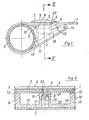
- the belt which is preferably intended for covering furniture, consists of a flat piece of tape 1 which, with its end region shown on the left in the drawing, around a bar 2 of any suitable frame of furniture, in particular a seat -or reclining furniture, foldable and its end 3 by means of a connecting device with the piece of tape 1 itself can be connected.
- the spar 2 of the furniture frame is designed in the illustrated embodiment as a cylindrical tube, as is customary in camping furniture for which the belt is preferably used. In principle, however, other cross-sectional shapes are also conceivable for the spars of the furniture frame, for example the shape of an ellipse.
- the right end of the band piece 1, which is not shown, can also preferably be fixed in the same manner and with the same connecting device on a spar which is correspondingly parallel and spaced apart.
- the band piece 1 can consist of a strip of plastic, of fiber-reinforced plastic, of textile fabric, of plastic fabric or the like. A strip of reinforced plastic or plastic fabric is preferred.
- the connecting device consists of an upper part 4 in the form of a flat, plate-shaped support piece 5, which only overlaps on the upper side in the connecting region in the assembly position of the parts, which has a flat or slightly concave curved upper side 6 and a flat lower side 7 and with at least one downward extending locking pin 8 is provided on its underside.
- the connecting device preferably has a width corresponding to the width of the band piece 1 and advantageously consists of a plastic injection molded body which is integral with the locking pin 8, e.g. made of hard PVC, polypropylene or similar strong plastic.
- the locking pin 8 of which two or three can also be provided, has a head 9 which is approximately arrow-shaped in cross section and which is intended for producing a snap lock which, if desired, cannot be released again.
- the connecting device further comprises a lower part 10, which at least essentially takes the form of the gusset space of the loop 11 at the end of the belt filling wedge body.
- This wedge body 10 in turn preferably consists of a plastic injection molded body made of solid material, has a width that essentially corresponds to the width of the band piece 1, a flat upper wedge surface 12 that engages under the band piece 1 in the connection area, a flat lower wedge surface 13 as a contact for the band end 3, one of which Main part of the band piece 1 facing, rounded wedge cutting edge 14 and a spar 2 facing the spar, which can be placed flush against it.
- the end face 15 is accordingly in the form of a partial arc of a circle.
- the wedge angle can have a value of approximately 30 to 60 ° and is determined as a function of the diameter or the dimensions of the spar 2 and the desired length of the wedge body 10 measured in the longitudinal direction of the band piece 1.
- the length of the wedge body 10 in turn determined the leverage effect. which is to be achieved when establishing the connection in a manner to be described below.
- the width of the wedge body 10 is preferably the same as that of the band piece 1 or that of the support piece 5.
- the wedge body 10 can in principle be designed as a solid solid piece and accordingly offer a closed end surface 15 and at least partially closed upper and lower wedge surfaces 12, 13. However, it can also preferably be designed as a hollow body, which has closed side walls 16, 17, an essentially closed lower wall 18 which presents the lower wedge surface 13 and between the side walls 16, 17 in the region of the upper wedge surface 12 and the region of the end surface 15 is open. In this case, both the upper wedge surface 12 and the end face 15 are formed only by the narrow sides of the side walls 16, 17.
- the side walls 16, 17 can also be arranged offset a little inwards), the weight and the material requirements of the wedge body 10 are still reduced, while still having sufficient strength.
- the wedge body 10 has a snap-in receptacle 19 for each locking pin 8, which is formed by opposite spreading tongues 20, separated by slots, which engage behind the head 9 with the upper inwardly directed hook parts 21 after the locking pin 8 has been inserted.
- the locking surfaces that come into engagement on the hook parts 21 and on the head 9 can be inclined slightly inwards so that the locking forces increase when the lifting force is directed upwards onto the upper part 4.
- the opposite expansion tongues 20 define a slot-shaped space 22 between them, and the head 9 has a corresponding dimension in the direction perpendicular to the plane of the drawing in FIG. 2, so that the snap-in receptacle 19 also forms an anti-rotation device for the locking pin 8 and thus the upper part 4. If the upper part 4 has two or more locking pins 8 and, accordingly, the lower part 10 has a plurality of locking receptacles 19, these parts can also be approximately rotationally symmetrical in cross section, since the anti-rotation device is then brought about by the plurality of locking pins 8 and locking receptacles 19.
- the space 22 between the expansion tongues 20 of the latching receptacle 19 preferably extends down into the lower wedge surface 13, so that there is the possibility, even when the connection between the upper and the lower part 4, 10 has been made, by inserting a tool with which the expansion tongues 20 moved apart to be able to pick up again.
- the band end 3 can be provided with a passage opening in the area opposite the lower opening of the intermediate space 22 in the wedge surface 13, contrary to the illustration in the drawing.
- the wedge body 1Q also has fastening means for fixing the band end 3 to the latter.
- these consist, for example, of an adhesive or welding agent for connecting the part of the strip end 3 which overlaps the upper wedge surface 12 to the upper narrow sides of the side walls 16, 17.
- a riveted connection can also be provided, which is not shown and is preferably also made in the region of the upper wedge surface 12 between suitable parts of the wedge body 10 and the part of the strip end which overlaps it.
- the fastening means for fixing the band end 3 to the wedge body 10 facilitate assembly, since the band end 3 and wedge body 10 become a unit which can be handled jointly, but it is also conceivable in principle to dispense with special fastening means if, as in FIGS. 1 and 2 the tape end 3 is practically brought up to the spar 2 and overlaps the locking point. In this case, it may be sufficient to provide the part of the band end 3 resting on the upper wedge surface 12 with a recess through which all parts of the locking pins 8 extend in the installed position. However, such training complicates assembly.
- the band piece 1 is provided in its connection area above the wedge body 10 at a suitable point with a recess 23 through which the locking pin 8 can be inserted into its latching receptacle 19.
- This recess is larger in the longitudinal direction of the band piece 1 than the dimension of the locking pin 8 given in this direction, so that the band piece 1 can shift somewhat in its longitudinal direction below the support piece 5 of the upper part 4.
- the loop 11 pulls firmly around the wedge body 10 and the spar 2 with a corresponding longitudinal tension of the band, so that the band end 3 has a clearly defined course and bears firmly against both the spar 2 and the wedge body 10.
- Change in use the Läncsspannun g values in the band piece 1 the area of the band piece 1 overlapped by the support piece 5 can slip under this in the longitudinal direction of the band, so that stresses on the edges of the recess 23 are avoided.
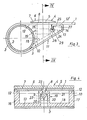
- the wedge body 10 is provided in its upper wedge surface 12 in its area 24 adjacent to the wedge cutting edge 14 and consisting of solid material there with a fastening transverse slot 25 which is provided for receiving and fixing the transverse edge area 27 of the band end 3.
- the fastening transverse slot 25 merges into an internal extension 28, which is preferably open at both ends, and on the transverse edge of the band end 3 there is a thickening 29 which can be inserted laterally into the extension 28 and which prevents the transverse edge region 27 from slipping out of the transverse fastening slot 25 as a retaining element.
- the thickening can be done by a separately attached, e.g. molded bead part or also be formed by a melt bead.
- the wedge surface 12 is stepped downward in the region 12 ′ overlapped by the band end 3, approximately by the thickness of the band end 3.
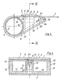
- the wedge body 10 is also provided in the region of its upper wedge surface 12 in its wedge edge 14 immediately adjacent region 1 4 with a Befest Trentsguerschlitz 30 for receiving and securing the transverse edge portion 27 of the tape end 3.
- This fastening transverse slot 30 extends approximately parallel to the lower wedge surface 13 and is designed as a clamping slot in which the transverse edge region 27 of the band end 3 is fixed in a clamping manner after it has been inserted.
- this fastening transverse slot 30 can also be provided with inwardly directed, barb-like projections 31 which engage in the transverse edge region 27 of the band end 3 and counteract slipping out in the opposite direction of the pull-in device.
- FIG. 7 A particularly preferred embodiment is illustrated in Figs. 7 and 8. Similar to the embodiment according to FIG. 3, the wedge body 10 is in turn provided with a fastening transverse slot 25, which, however, takes its exit from the flat lower wedge surface 13. There is no need to round off the wedge cutting edge 14, which is accordingly bluntly cut off here. The gradation of the upper wedge surface 12 is also unnecessary.
- two locking pins 8 are provided which are designed as sliding pieces and have a head which is formed by projections 32 which project in the transverse direction. On its side facing the spar 2, the locking pin 8 is provided at the level of its head 32 with an extension lug 33 which counteracts the release of the locking lock after the locking pins 8 have been inserted into the locking recess 19.
- the locking receptacle 19 for each locking pin 8 is designed as a groove 34, which is provided with locking lugs 35 which overlap the lugs 32 after the locking pins 8 have been inserted.
- This design enables the upper part to be attached in a sliding movement in FIG. 7 from left to right, which is initially introduced obliquely downward and then continued parallel to the upper side 12 until the lugs 32 of the head of the locking pins 8 completely engage under the lugs 35 of the groove 34.
- the band end 3 together with the wedge body 10 connected to it, is looped around the spar 2 until the wedge body is in the drawing illustrated location has reached. Then the upper part 4 is attached, and the connection is completed when the locking pin 8 has come into locking engagement in its receptacle 19.
- the wedge body 10 can first be placed with its end face 15 on the spar, after which the wedge body 10 is pivoted around the spar 2 under pressure on its lower wedge surface 13 overlapped by the band end 3. During this pivoting around, the wedge body 10 acts as a lever which reduces the compressive force to be applied, while at the same time the band piece 1 or the band end 3 slips around the spar 2 and receives its desired longitudinal band tension. As soon as the wedge body 10 rests with its upper wedge surface 12 on the band piece 1 in the connection region, the upper part 4 can then be attached between the locking pin 8 and its latching receptacle 19 while producing the locking mechanism.
Landscapes
- Clamps And Clips (AREA)
- Buckles (AREA)
- Package Frames And Binding Bands (AREA)
Applications Claiming Priority (2)
| Application Number | Priority Date | Filing Date | Title |
|---|---|---|---|
| DE3237124A DE3237124C2 (de) | 1982-10-07 | 1982-10-07 | Gurt, insbesondere Bespannungsgurt für Möbel |
| DE3237124 | 1982-10-07 |
Publications (2)
| Publication Number | Publication Date |
|---|---|
| EP0106233A2 true EP0106233A2 (fr) | 1984-04-25 |
| EP0106233A3 EP0106233A3 (fr) | 1984-10-17 |
Family
ID=6175148
Family Applications (1)
| Application Number | Title | Priority Date | Filing Date |
|---|---|---|---|
| EP83109732A Withdrawn EP0106233A3 (fr) | 1982-10-07 | 1983-09-29 | Sangle, en particulier sangle de tension pour meuble |
Country Status (3)
| Country | Link |
|---|---|
| US (1) | US4541150A (fr) |
| EP (1) | EP0106233A3 (fr) |
| DE (1) | DE3237124C2 (fr) |
Families Citing this family (16)
| Publication number | Priority date | Publication date | Assignee | Title |
|---|---|---|---|---|
| US5445436A (en) * | 1992-10-15 | 1995-08-29 | Sunbeam Corporation | Backing or seating for seating type furniture and means for securing backing or seating to a frame |
| US6560827B1 (en) * | 2001-08-14 | 2003-05-13 | Gross Jan S | Elastomeric gasket for sling rail furniture |
| US7021718B2 (en) | 2002-12-02 | 2006-04-04 | Dahti, Inc. | Method and apparatus for attaching accessories to load-bearing fabric |
| JP5005167B2 (ja) * | 2004-10-13 | 2012-08-22 | 株式会社岡村製作所 | 椅子の背凭れ構造 |
| US7448689B2 (en) * | 2005-04-04 | 2008-11-11 | La-Z-Boy Incorporated | Modular furniture attachment strap |
| US7591511B2 (en) | 2005-12-12 | 2009-09-22 | Mity-Lite, Inc. | Tamper resistant attachment device for a chair backrest |
| US7730594B2 (en) * | 2007-02-12 | 2010-06-08 | Yun-Chien Hsiao | Connector for stretch straps of a chair |
| US8317269B2 (en) | 2008-12-24 | 2012-11-27 | Mity-Lite, Inc. | Mesh stacking chair |
| US8322787B2 (en) | 2008-12-24 | 2012-12-04 | Mity-Lite, Inc. | Clamping joint for a chair |
| US8033598B2 (en) | 2008-12-24 | 2011-10-11 | Mity-Lite, Inc. | Mesh folding chair |
| US8454093B2 (en) | 2008-12-24 | 2013-06-04 | Mity-Lite, Inc. | Mesh chair with open-end hoop |
| USD599127S1 (en) | 2009-04-13 | 2009-09-01 | Mity-Lite, Inc. | Mesh folding chair |
| USD648554S1 (en) | 2009-11-04 | 2011-11-15 | Mity-Lite, Inc. | Mesh stacking chair |
| USD660612S1 (en) | 2010-11-16 | 2012-05-29 | Mity-Lite, Inc. | Mesh banquet chair |
| FR3055809B1 (fr) * | 2016-09-15 | 2018-10-05 | Zedel | Harnais equipe de points de connexion ergonomiques |
| US20200069069A1 (en) * | 2018-08-29 | 2020-03-05 | Chuan-Hang Shih | Lightweight electric bedstead |
Family Cites Families (14)
| Publication number | Priority date | Publication date | Assignee | Title |
|---|---|---|---|---|
| GB565221A (en) * | 1943-03-09 | 1944-11-01 | Muriel Alberta Horsford | Improvements relating to resilient surfaces for seats, beds and the like |
| US2582579A (en) * | 1948-02-05 | 1952-01-15 | United Carr Fastener Corp | Fastener |
| GB800828A (en) * | 1955-12-01 | 1958-09-03 | Lucian Randolph Ercolani | Means for securing resilient ribbon-like elements to rigid members |
| US2979119A (en) * | 1958-09-29 | 1961-04-11 | Kramer Hyman | Web-to-tube fastenings |
| US3042113A (en) * | 1959-11-12 | 1962-07-03 | Kramer Hyman | Web-to-tube fastenings |
| US3088517A (en) * | 1961-11-08 | 1963-05-07 | Medallion Corp | Webbing strip connector for metallic furniture |
| GB964853A (en) * | 1962-04-26 | 1964-07-22 | Canadian Celanese Ltd | Improvements in tape stringers for a seat, bed or like article of furniture |
| US3167836A (en) * | 1963-11-18 | 1965-02-02 | Leonard D Walter | Hook fastener for furniture webbing |
| US3263294A (en) * | 1964-03-20 | 1966-08-02 | William J Pappas | Support |
| US3438099A (en) * | 1967-10-13 | 1969-04-15 | Harold Green | Fastener connections |
| US3464479A (en) * | 1967-11-22 | 1969-09-02 | Bertrand M Baker | Webbed furniture construction |
| US3910339A (en) * | 1971-12-13 | 1975-10-07 | Hyman Kramer | Webbing strip-to-tubular frame member fastenings |
| US3960197A (en) * | 1974-11-08 | 1976-06-01 | Daniels Phillip D | Screen and storm sash construction |
| US4280548A (en) * | 1977-09-23 | 1981-07-28 | Manfred Brokmann | Furniture such as chairs and couches |
-
1982
- 1982-10-07 DE DE3237124A patent/DE3237124C2/de not_active Expired - Fee Related
-
1983
- 1983-09-27 US US06/536,413 patent/US4541150A/en not_active Expired - Fee Related
- 1983-09-29 EP EP83109732A patent/EP0106233A3/fr not_active Withdrawn
Also Published As
| Publication number | Publication date |
|---|---|
| EP0106233A3 (fr) | 1984-10-17 |
| DE3237124C2 (de) | 1994-06-30 |
| US4541150A (en) | 1985-09-17 |
| DE3237124A1 (de) | 1984-04-12 |
Similar Documents
| Publication | Publication Date | Title |
|---|---|---|
| DE2032858C3 (fr) | ||
| DE19754121B4 (de) | Mehrzweckclip | |
| DE3003141C2 (de) | Klemmschelle | |
| DE3237124C2 (de) | Gurt, insbesondere Bespannungsgurt für Möbel | |
| DE1934590B2 (fr) | ||
| DE2633972B2 (de) | Anordnung zum Verbinden zweier Bauteile | |
| DE2010344A1 (de) | Befestigungsschelle | |
| DE2429190C2 (de) | Befestigungsband | |
| DE1903372C3 (de) | Halteschelle für Rohre, Kabel und dergl | |
| DE19829332B4 (de) | Gurthalter | |
| EP3652462A1 (fr) | Système comprenant un serre-cordon et au moins un cordon | |
| DE2360992A1 (de) | Halteband | |
| EP0389831A2 (fr) | Dispositif pour ligaturer des éléments allongés | |
| DE7724913U1 (de) | Verschluss- oder Befestigungsband aus Kunststoff Gummi oder aehnlichen Werkstoffen | |
| DE1231614B (de) | Verschlussband aus flexiblem Kunststoff | |
| DE19650969C1 (de) | Gefäßstauer mit Gurt und Schnalle | |
| EP0439053B1 (fr) | Fermeture pour ajuster des ceintures de sécurité | |
| DE2850665A1 (de) | Einrichtung zum schliessen von schuhen | |
| DE8208609U1 (de) | Vorrichtung zur Befestigung von Bespannungsgurten | |
| DE1865629U (de) | Tragetasche aus kunststoff. | |
| DE2204809C3 (de) | Klemmvorrichtung für längenverstellbare Gurte o.dgl | |
| DE1966002U (de) | Befestigungsvorrichtung fuer eine zierleiste od. dgl. insbesondere an einer karosserie von kraftfahrzeugen. | |
| DE1490157C (de) | Bindegurt aus Kunststoff | |
| CH568896A5 (en) | Bundle harness device - has laddered strap which engages locking tang in holding head | |
| DE4031358A1 (de) | Knieschuetzer |
Legal Events
| Date | Code | Title | Description |
|---|---|---|---|
| PUAI | Public reference made under article 153(3) epc to a published international application that has entered the european phase |
Free format text: ORIGINAL CODE: 0009012 |
|
| AK | Designated contracting states |
Designated state(s): AT DE GB IT NL |
|
| PUAL | Search report despatched |
Free format text: ORIGINAL CODE: 0009013 |
|
| AK | Designated contracting states |
Designated state(s): AT DE GB IT NL |
|
| 17P | Request for examination filed |
Effective date: 19841215 |
|
| STAA | Information on the status of an ep patent application or granted ep patent |
Free format text: STATUS: THE APPLICATION HAS BEEN WITHDRAWN |
|
| 18W | Application withdrawn |
Withdrawal date: 19860926 |