EP0106237B1 - Verpackungsartikel für die automatische und kontinuierliche Herstellung von Würsten mit flachen Enden - Google Patents
Verpackungsartikel für die automatische und kontinuierliche Herstellung von Würsten mit flachen Enden Download PDFInfo
- Publication number
- EP0106237B1 EP0106237B1 EP83109743A EP83109743A EP0106237B1 EP 0106237 B1 EP0106237 B1 EP 0106237B1 EP 83109743 A EP83109743 A EP 83109743A EP 83109743 A EP83109743 A EP 83109743A EP 0106237 B1 EP0106237 B1 EP 0106237B1
- Authority
- EP
- European Patent Office
- Prior art keywords
- disks
- disk
- casing
- article
- annular
- Prior art date
- Legal status (The legal status is an assumption and is not a legal conclusion. Google has not performed a legal analysis and makes no representation as to the accuracy of the status listed.)
- Expired
Links
- 235000013580 sausages Nutrition 0.000 title description 27
- 235000013305 food Nutrition 0.000 claims description 25
- 239000012528 membrane Substances 0.000 claims description 24
- 238000004513 sizing Methods 0.000 claims description 20
- 238000000034 method Methods 0.000 claims description 17
- 238000004519 manufacturing process Methods 0.000 claims description 10
- 238000011065 in-situ storage Methods 0.000 claims 1
- 239000000839 emulsion Substances 0.000 description 10
- -1 polyethylene Polymers 0.000 description 10
- 239000004606 Fillers/Extenders Substances 0.000 description 7
- 239000004698 Polyethylene Substances 0.000 description 7
- 239000000463 material Substances 0.000 description 7
- 229920000573 polyethylene Polymers 0.000 description 7
- 238000002788 crimping Methods 0.000 description 4
- 229920003023 plastic Polymers 0.000 description 4
- 239000004033 plastic Substances 0.000 description 4
- 230000008569 process Effects 0.000 description 4
- 229910000831 Steel Inorganic materials 0.000 description 3
- 239000011324 bead Substances 0.000 description 3
- 235000013372 meat Nutrition 0.000 description 3
- 239000002184 metal Substances 0.000 description 3
- 229910052751 metal Inorganic materials 0.000 description 3
- 239000002985 plastic film Substances 0.000 description 3
- 229920006255 plastic film Polymers 0.000 description 3
- 239000004800 polyvinyl chloride Substances 0.000 description 3
- 229920000915 polyvinyl chloride Polymers 0.000 description 3
- 239000010959 steel Substances 0.000 description 3
- PPBRXRYQALVLMV-UHFFFAOYSA-N Styrene Chemical compound C=CC1=CC=CC=C1 PPBRXRYQALVLMV-UHFFFAOYSA-N 0.000 description 2
- 239000011248 coating agent Substances 0.000 description 2
- 238000000576 coating method Methods 0.000 description 2
- 238000013461 design Methods 0.000 description 2
- 230000000694 effects Effects 0.000 description 2
- 230000007246 mechanism Effects 0.000 description 2
- 238000004806 packaging method and process Methods 0.000 description 2
- 239000004627 regenerated cellulose Substances 0.000 description 2
- 229920000298 Cellophane Polymers 0.000 description 1
- 239000004743 Polypropylene Substances 0.000 description 1
- 241001237745 Salamis Species 0.000 description 1
- 241000219793 Trifolium Species 0.000 description 1
- 230000001154 acute effect Effects 0.000 description 1
- 239000000853 adhesive Substances 0.000 description 1
- 230000001070 adhesive effect Effects 0.000 description 1
- 229910052782 aluminium Inorganic materials 0.000 description 1
- XAGFODPZIPBFFR-UHFFFAOYSA-N aluminium Chemical compound [Al] XAGFODPZIPBFFR-UHFFFAOYSA-N 0.000 description 1
- 238000013459 approach Methods 0.000 description 1
- 230000015572 biosynthetic process Effects 0.000 description 1
- DQXBYHZEEUGOBF-UHFFFAOYSA-N but-3-enoic acid;ethene Chemical compound C=C.OC(=O)CC=C DQXBYHZEEUGOBF-UHFFFAOYSA-N 0.000 description 1
- 238000007744 chromate conversion coating Methods 0.000 description 1
- 238000005056 compaction Methods 0.000 description 1
- 238000010276 construction Methods 0.000 description 1
- 238000007599 discharging Methods 0.000 description 1
- 239000005038 ethylene vinyl acetate Substances 0.000 description 1
- 230000006872 improvement Effects 0.000 description 1
- 230000014759 maintenance of location Effects 0.000 description 1
- 230000013011 mating Effects 0.000 description 1
- 238000005259 measurement Methods 0.000 description 1
- 235000015255 meat loaf Nutrition 0.000 description 1
- 150000002739 metals Chemical class 0.000 description 1
- 229920001200 poly(ethylene-vinyl acetate) Polymers 0.000 description 1
- 229920001155 polypropylene Polymers 0.000 description 1
- 238000012545 processing Methods 0.000 description 1
- 230000001681 protective effect Effects 0.000 description 1
- 239000012858 resilient material Substances 0.000 description 1
- 230000000717 retained effect Effects 0.000 description 1
- 235000015175 salami Nutrition 0.000 description 1
- 239000000779 smoke Substances 0.000 description 1
- 239000007787 solid Substances 0.000 description 1
- 229920006302 stretch film Polymers 0.000 description 1
- 238000012360 testing method Methods 0.000 description 1
Images


Classifications
-
- A—HUMAN NECESSITIES
- A22—BUTCHERING; MEAT TREATMENT; PROCESSING POULTRY OR FISH
- A22C—PROCESSING MEAT, POULTRY, OR FISH
- A22C11/00—Sausage making ; Apparatus for handling or conveying sausage products during manufacture
- A22C11/02—Sausage filling or stuffing machines
- A22C11/0281—Sausage filling or stuffing machines for sausages having at least one flat end
Definitions
- This invention relates generally to the production of large sausage products, and, more specifically, to a package article useful in continuously producing such products with flat ends.
- Large sausage casings are generally manufactured from materials such as regenerated cellulose, or regenerated cellulose having fibrous webs embedded therein, and are employed in the manufacture of large sausage products such as salami and bologna sausages, spiced meat loafs, cooked and smoked ham butts and the like.
- Such large sausage casings are produced in flat widths ranging in size from about 50 to 380 mm and range in length from about 355 to 1830 mm and longer.
- the large sausage casings most commonly used for commercial production of large sausage products range in size from about 76 to 203 mm in flat width and from about 457 to 1830 mm in length.
- a large sausage casing In the production of a large sausage product, a large sausage casing is first gathered over the end of a stuffing horn and then stuffed with a food emulsion. The thusly stuffed and encased food emulsion is subsequently cooked or cured according to conventional processes. Many of these large sausage products are thereafter sliced and packaged into units of predetermined weight and slice count for retail sale.
- the slicing devices employed in such packaging operations are preset to yield a specific weight-by-slice count for use in obtaining unit packages of equal weight.
- US-A-3,808,638 discloses a method for producing large sausage products having one pre-flattened end. Although this method reduces the sausage end rework by one-half, substantial rework is still present in the non-flattened end.
- US-A-3,777,331 discloses a method and apparatus for producing encased sausage with two flat ends whereby the end pieces are inserted in a non-fully automatic fashion. Such method and apparatus is limited to the use of continuous lengths of non-shirred casing, and does not lend itself to efficient commercial operation.
- a package casing article including a shirred casing having an unshirred portion, is characterized in that, a plurality of flattening annular disks are disposed inside said unshirred portion, said disks being detachably attached in pairs, the pairs of disks being attached by a flexible means which connects a disk of one pair to a disk of an adjoining pair.
- each of the annular disks has a central opening.
- the diameter of the central opening in each of said annular disks generally does not exceed 99 percent (preferably 90 percent, more preferably 50 percent) of the annular disk outer diameter.
- the disks can be overwrapped with a rigid or flexible material.
- Each of the annular disks should have an outer diameter less than the casing burst diameter for said casing.
- casing burst diameter denotes a diameter that is excessive to the extent that the casing integrity is lost and there is at least one break-point in the casing.
- the present invention relates to a method of making a package casing article for use in automatically and continuously stuffing a food product comprising the steps of:
- FIG. 1 wherein reference number 25 generally designates the prepackaged shirred tubular casing article of the invention.
- the prepackaged tubular casing article includes a shirred casing stick 1 having an unshirred portion 2.
- a sizing means in the form of a sizing disk 3 is implanted in the unshirred portion 2 of said shirred casing stick 1. Said sizing disk and its functions are described in US-A-4,007,761, US-A-4,077,090 and US-A-4,164,057 and US-E-30,265 and US-E-30,390, all incorporated herein by reference.
- At least two flattening annular disks are implanted within the unshirred portion 2 , shown in Fig. 1 as disk pair 30a, which includes a trailing annular disk 8 and a leading annular disk 9.
- the terms "leading” and “trailing” as applied to the disk are defined hereinbelow.
- the term "flattening annular disk” is used to designate any disk which has a central hole and which, when employed as an insert at either end of the stuffed sausage product, will at least partially (and preferably fully) flatten the end of such product, thereby producing a product generally having the shape of a right circular cylinder.
- a stuffed product having flat ends makes it possible to avoid or minimize rework resulting from the rounded ends associated with conventional sausages.
- the flattening annular disks can have any of a wide variety of shapes and sizes including for example, round, elliptical, oval, and polygonal-with-rounded corners, provided that these disks generally conform in outer perimeter to the inner perimeter of the unshirred portion of the casing of the package article. In this regard, it is important that a tight seal exists between the inner casing perimeter and the outer annular disk perimeter so that a seal may be maintained during the stuffing operation and subsequent handling of the food product.
- the annular disks are round in shape they preferably should have a central hole diameter not exceeding 90 percent of the annular disk outer diameter, although it is more preferable that the central hole diameter not exceed one-half the annular disk outer diameter.
- the effective diameter of the central hole should preferably not exceed 90 (more preferably 50) percent of the effective annular disk outer diameter.
- the central hole diameter of the annular disks approaches 99 percent of the annular disk outer diameter, the annular disks are properly envisioned as hoops.
- hoops When using such hoops, they should be arranged in the form of the hereinafter-discussed extender modules. In the stuffed product, the hoops co-act with the flexible tubular membrane of the extended modules to prevent formation of hemispherical product ends and, instead, to provide substantially flat ends.
- the central hole in the annular disks can also have a wide variety of sizes and shapes including, for example, round, elliptical, oval, and polygonal-with-rounded-corners. It is most preferable to have as small a central hole as possible in the annular disks since this will facilitate maximum flattening of the meat or meat-emulsion ends in the casing. Of course, the central hole in the annular disks cannot be smaller than the diameter of the stuffing horn or support tube upon which the annular disks are to be mounted, as further described hereinbelow.
- the disks in themselves be supported in some fashion in order to insure their ordered integrity in a disk array 6 in the prepackaged, shirred tubular casing article 25, during shipping and handling, and before and during stuffing operations.
- two preferred support mechanisms would include an overwrap.15 (either rigid or flexible) or a central support tube 12, or both.
- Typical overwrap for the annular disks would include flexible film such as polyvinylchloride film or polyethylene film.
- the central support tube 12, if used, would be one extending through at least a portion of the disk array 6. In a preferred embodiment, the support tube would be one that essentially fills the available cross sectional area provided by the central holes in the annular disks.
- the support tube if used, preferably has a circular or elliptical cross section, more preferably an elliptical cross section.
- An elliptical central support tube is particularly preferred when using annular disks with a circular central hole since such a support tube configuration affords a maximum effective cross-section to the support tube for maximum food emulsion throughout while enabling the disks to be angularly disposed on the support tube as further described hereinbelow.
- One or more of the above-described flattening annular disks can act as a sizing disk, performing a casing sizing function (i.e., circumferentially stretching the casing) as well as a flattening function.
- a casing sizing function i.e., circumferentially stretching the casing
- at least some portion of the sizing function will be performed by one or more of the annular disks, either alone, or co-acting with an optional sizing means, if used.
- Useful optional sizing means are described in US-A-4,007,761; US-A-4,077,090; and US-A-4,164,057 and US-E-30,265 and US-E-30,390 referenced above, all incorporated herein by reference.
- the flattening annular disks are detachably-attached in pairs, such as disk pairs 30a, b, c, etc.
- at least one disk of the pair is fixedly-attached by flexible means (preferably by means of a flexible tubular membrane) to a disk of an adjoining disk pair as more fully described hereinafter in conjunction with the drawings.
- flexible means preferably by means of a flexible tubular membrane
- Such a mode of attachment serves, among other things, as a vehicle to move the disks in pairs into position on the stuffing horn or stuffing horn extension and off the stuffing horn at appropriate times in the stuffing cycle.
- the leading annular disk i.e., the disk that is in place in the leading end of the sausage product
- each detachably-attached pair have a central hole having a diameter that is larger than the central hole diameter of the trailing annular disk in the pair.
- This difference in hole diameters between the leading and trailing disks can permit the trailing disk to be retained on the end of the stuffing horn or stuffing horn extension during stuffing operations while the leading disk passes over such end.
- the disk can have central holes that are of comparable annular diameters.
- one disk in the array namely the very first disk, can be a solid disc with no central hole.
- Detachable-attachment of the leading and trailing disks of each disk pair 30a, b,c, etc. can be effected by any suitable means such as, for example, metal or plastic tabs located around the inner or outer perimeter of one disk which co-act with a mating surface on an adjoining disk to form a disk pair.
- a preferred mode of detachable-attachment involves the use of metal tabs located around the outer perimeter of one annular flattening disk of the pair which interlocks with the other of the pair as hereinafter more fully described in connection with the drawings.
- Fixed-attachment of the flexible tubular membrane 7 between the annular disks of one pair and the annular disk of an adjacent pair is preferably effected in proximity to the inner perimeter of such annular disk by any suitable means, such as by employing a food-acceptable metal-to-plastic adhesive or by crimping the inner perimeter of the disk around the flexible tubular membrane. If the crimping method is used, care must be taken to avoid tearing the membrane during the crimping process. In this regard, it has been found advantageous to employ a plastic, e.g. polyethylene string inside the crimp itself to act as a cushion during the crimping process, thereby minimizing the possibility of tearing the flexible tubular membrane.
- a plastic e.g. polyethylene string inside the crimp itself to act as a cushion during the crimping process, thereby minimizing the possibility of tearing the flexible tubular membrane.
- the flexible tubular membrane 7 as may be useful for fixed-attachment purposes is preferably a membrane constructed of a plastic film such as, for example, polyethylene film, polyvinyl chloride film or ethylene vinylacetate film. Polyethylene film is preferred.
- this flexible tubular membrane will permit the disk pairs 30b, c, d, etc. to collapse one against the other to form the relatively compact, ordered disk array 6 of disk pairs 30b, c, d, etc. It is preferred that the flexible tubular membrane occupy a minimum of space when fully collapsed in order to minimize the length of this array 6 of disk pairs.
- the number of trailing and leading flattening annular disks in the package article be at least two. It is preferred that the number of disks be sufficient to provide sausages of a length required in any given commercial situation, taking into account the length of casing available on the shirred stick in the package article and the length of the encased stuffed product required for a particular commercial operation.
- the required number of disks will be readily apparent to one of ordinary skill in the art, although it is preferred that the number of disks be at least ten.
- either the length of casing in the shirred stick can be varied based on a fixed number of disks or the number of disks can be varied based on a fixed shirred stick length.
- a casing having a stuffed diameter of about 114 mm and an unshirred casing length of 61 m might employ 50 of the disk pairs 30a, b, c, etc.
- the flattening annular disks useful in the present invention can be made of a wide variety of materials provided that the surface of the material chosen, or coating on the surface of the materal, meet the required government specifications for use with food products.
- Useful materials would include metals such as aluminum and steel, and plastics such as styrene and polypropylene. It is preferred that the disks each be of sufficient strength to resist deformation in the stuffed product.
- the preferred disks of the present invention are those constructed from 34 kg, tin-plated steel having a thickness of about 0.18 mm and having stiffening annular ribs, such as those often found in can lids, for added support.
- the tin-plated steel may be appropriately coated with a chromate conversion coating or other coating meeting the required government specifications for use with food products.
- an unshirred portion of casing length 2 passes over the first disk pair 30a and the disk array 6.
- the fore end of casing length 2 is closed, together with a portion of the flexible tubular membrane 7 attached to leading annular disk 9 of said first disk pair 30a, with a clip 44.
- the trailing annular disk 8 of said first disk pair 30a is detachably-attached to said leading annular disk 9 and fixedly-attached by means of a second piece of flexible tubular membrane 7 to the leading annular disk 9 of the next disk pair 30b.
- the flexible tubular membrane 7 serves as the link between the disk pairs of the disk array 6 and preferably serves as a vehicle to move the disk pairs from an inclined position in the disk array 6 to an upright position as shown for disk pair 30a.
- the disk array 6 is preferably disposed in a fashion such that the disks therein are stacked at an acute angle to the longitudinal axis of the casing length 2 in order to allow free movement of the unshirred portion of the casing over the array during the stuffing operation.
- an overwrap 39 which, as set forth hereinabove, is utilized to cover the shirred casing length portion 1 of the package article 25 as well as the rest of the article.
- Said overwrap provides a protective covering for, and a degree of structural integrity to, the whole of the subject package article, and also provides a degree of moisture retention for the casing.
- the overwrap 39 is disposed in a manner to provide free access to the internal bore of the shirred casing stick 1 of the subject package article.
- overwrap is preferably a plastic film with elastic properties
- other types of overwrap material could be utilized such as shrink or non-shrink plastic film, cellophane, paper, elastic netting and the like.
- a preferred overwrap is an elastic stretch film comprising polyvinyl chloride, but a shrink fitted overwrap comprising polyethylene film is also suitably employed.
- a second preferred overwrap is a closed flexible bag of polyethylene.
- the subject article of the invention In use, the subject article of the invention, provided as a package article unit to the customer, is loaded on a stuffing apparatus.
- Fig. 2 shows one embodiment of the package article 25 in place in such a stuffing horn 5 of a stuffing apparatus.
- the shirred casing stick 1 of the subject invention is placed on the movable support sleeve 24 of said stuffing apparatus, and the sizing disk 3 is attached to the support sleeve by means of the frangible "fingers" of said sizing disk.
- FIG. 1 and 2 show that the support tube 12, on which the array is mounted, includes a quick-connection attachment means 26 which attaches to a corresponding connector on the stuffing horn of said stuffing apparatus.
- One of the functions served by said support tube 12 is to maintain the ordered integrity of the annular disks in the package article.
- seal means 8a and positioning means 8b of said stuffing apparatus are seal means 8a and positioning means 8b of said stuffing apparatus.
- the seal means is preferably a split seal ring that, in use, provides a tight seal between an unshirred portion of casing length 2 and trailing annular disk 8 of first disk pair 30a during the first stuffing cycle and between subsequent casing lengths and trailing disks for subsequent stuffing cycles.
- the positioning means preferably consists of a crescent-shaped ring adapted for fore-and-aft motion over disk array 6, and further adapted to move pairs of disks out of the array and into the stuffing position occupied by first disk pair 30a.
- the seal means and the positioning means are more clearly discussed in copending European patent application 83109744.9 (EP - A-0106238).
- the stuffing apparatus which can be employed in conjunction with the package article of the present invention is suitably a modified version of that set forth in US-E-30,390, incorporated herein by reference.
- the support sleeve as disclosed in that reissue patent is fixed in place on the stuffing horn and does not move during the stuffing operation.
- the sizing disk of that reissue patent is rendered not movable on the stuffing horn.
- the sizing disk of the reissue patent can be made small enough to provide a degree of stretch-sizing, when used in conjunction with the slideable snubbing means of the reissue patent, (modified to make it slideable), while permitting casing slacking when required during the casing closing cycle.
- a preferred apparatus is described in detail in copending EP application 83 109744.9 (EP-A-0 106 238) also incorporated herein by reference.
- the package article of the present invention is envisioned to work with a wide variety of other apparatus that may be devised by those working in the field.
- the system disclosed in our EP application 83 109 744.9 involves an apparatus for automatically and continuously producing an encased food product having a uniform diameter and substantially flat ends comprising in combination, a frame, a stuffing horn assembly, including a support tube having an inlet end and a discharge end for conveying food product from a supply source, said support tube having a first portion adapted to carry a shirred tubular casing article and said support tube having a tube portion adapted to hold an unshirred portion of said shirred tubular casing article including a plurality of axially disposed flattening annular disks inside said unshirred portion of casing, said tube portion extending through the central holes of said annular disks, means for advancing selected ones of said flattening annular disks to said discharge end and thereafter introducing a food product to be stuffed between said flattening annular disks, and control means operatively associated with said stuffing horn assembly to selectively control a cycle of successive stuff
- EP-A-0 106 2378 involves a method for automatically and continuously producing encased food product having a uniform diameter and substantially flat ends which comprises:
- the package article of the present invention is suitable for use with the so-called cored high density (CHD) system as set forth in GB-A-21 02 267, incorporated herein by reference.
- the CHD system involves flexible tubular cellulosic food casing shirred and compressed onto a rigid hollow tubular core to a high compaction condition to produce a casing stick with enhanced stuffing length capacity, structural stability and strength, and larger stuffing horn adaptability.
- the sizing means employed in the present invention is molded to the tubular core of the CHD casing article.
- the stuffing horn itself or as a tension sleeve fitting over a stuffing horn, such as the tension sleeve disclosed in U.S. Patent 4,007,761. If the tubular core is used as the stuffing horn it may require support at the stuffing end in order to insure stability and prevent flopping or axial misalignment.
- FIG. 3 An alternate and preferred embodiment of the present invention is shown in Fig. 3 wherein a single-piece support tube 63 is shown fit over a stuffing horn assembly including a stuffing horn 65 and stuffing horn extension 67.
- the single-piece support tube 63 comprises a conical nose piece 69 having a flexible end lip 70, an elliptical support sleeve 71 for carrying an array of the disk pairs, a sizing means 73, and a disk array overwrap tie-down slot 74 all fit together with a CHD tubular core 75 to provide strength and coherency advantages that are associated with single piece construction.
- Fig. 3 An alternate and preferred embodiment of the present invention is shown in Fig. 3 wherein a single-piece support tube 63 is shown fit over a stuffing horn assembly including a stuffing horn 65 and stuffing horn extension 67.
- the single-piece support tube 63 comprises a conical nose piece 69 having a flexible end lip 70, an elliptical support
- FIG. 4 shows a package article utilizing the above-discussed single-piece support tube on which is mounted a shirred casing stick 77 and an unshirred casing length 79. Disposed within the unshirred casing length is a disk pair array 81 and an array overwrap 82, all mounted thereon.
- the disk array 81 is preferably canted for use during stuffing as shown in Fig. 4. Since the casing to be stuffed will have an inner diameter approaching the outer diameter of the disk array 81, the canting will allow the casing to be drawn over the disk array and its overwrap 82 during the stuffing operation with minimal drag. This allows the support tube 71 and the stuffing horn extension to be generally elliptical in vertical cross-section (see Fig. 5) because the projection of the round, but canted, central holes of the disk array 81 onto a plane normal to the axis of the stuffing horn will be an ellipse. This elliptical shape for the stuffing horn affords maximum emulsion through put during stuffing.
- a preferred shape of sizing means 73 is a cloverleaf design as shown in Fig. 5. This type of sizing means cooperates with means external to the casing to stretch-size the casing into the recesses and over the lands of the clover leaf to provide the desired effective diameter.
- Fig. 6 shows two annular disks useful in the present invention, fixedly-attached as generally indicated at 110 (hereinafter called an “extender module”) which can be adapted for use in the automatic production of large sausage products having flat ends.
- the extender module 110 includes a leading disk 112 and a trailing disk 114 connected by a flexible tubular membrane 116.
- leading and trailing denotes whether the particular disk forms the leading end, or the trailing end respectively, of a stuffed product.
- trailing disk 114 will go to form a flat trailing end of a first stuffed product during the stuffing operation while leading disk 112 will go to form a flat leading end of the next stuffed product.
- Each disk 112, 114 as shown in Fig. 6, is generally the shape of a substantially flat, annular disk.
- the central opening 118 in leading disk 112 is larger in diameter than the central opening 120 in trailing disk 114 for purposes set out herein below.
- each opening 118, 120 be as small as possible as this will facilitate maximum flattening of the ends of the stuffed product. Since in a preferred embodiment, both disks will be located on a stuffing horn assembly, the size of the opening 118, 120 should be sufficient to allow passage of the stuffing horn.
- Each disk 112, 114 is slightly dished about its opening as shown at 122. In part, this strengthens each disk and helps to prevent deformation in use.
- the portion of each disk about openings 118, 120 is also bent inward and formed about a core 124 of polyethylene or other suitable, relatively. resilient material. Captured between each core and the material of the disk as formed about these cores, are the respective ends 126, 128 of the tubular membrane 116. In this fashion the tubular membrane defines a tubular passage having one end 126 defined by opening 118 in the leading disk 112 and its second end 128 defined by opening 120 in the trailing disk 114.
- Leading disk 112 has a bead or rim 130 formed about the outer periphery to add strength and rigidity to the disk. Since, in use, disk 112 will be disposed within a stuffed casing, the bead also will help to prevent the disk from damaging the casing during the stuffing process as the casing is stretched over the bead to effect a seal between the inner perimeter of the casing and the outer perimeter of the leading disk 112.
- annular shoulder 134 Formed on the rear, or outwardly facing surface of the leading disk 112, is an annular shoulder 134. This shoulder is disposed about the leading disk adjacent to its outer periphery for purposes set out herein below.
- the trailing disk 114 has its outer periphery formed with a flange 136 that is bent or rounded over the front or leading face 138 of the disk.
- This configuration provides the rim of the trailing disk 114 with a rounded surface so that in use, a casing can be stretched over the trailing disk to effect a seal similar to the seal between the casing and the leading disk.
- This configuration also provides an annular lip 140 which extends about the periphery of the trailing disk. This lip is not continuous but has pieces removed so as to form a plurality of tabs 140, spaced about the periphery of the trailing disc.
- Tabs 140 on the trailing disk 114 and the shoulder 134 on the leading disk are coincident, and the respective sizes of shoulder 134 and tabs 140 are such that the shoulder can snap-fit under the tabs.
- a leading disk 112 of one extender module can be detachably connected to the trailing disk 114 of a second extender module simply by aligning the respective leading and trailing disks and then snapping shoulder 134 beneath the tabs 140 as shown in Fig. 7.
- a leading and a trailing disk which are detachably connected together as shown in Fig. 7 will be referred to as a disk pair and will be identified by letters A, B, C, etc.
- Fig. 7 shows a disk pair A formed by detachably connecting a leading disk 112 of one extender module 110 (Fig. 6), to the trailing disk 114 of another identical extended module.
- any number of extender modules 110 can be detachably connected to form an ordered array of disk pairs A, B, C, etc., each disk pair being connected to the following disk pair by flexible tubular membrane 116.
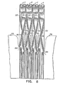
- Such an arrangement is shown in Fig. 8.
- Fig. 8 shows four disk pairs A, B, C and D connected one to another by tubular membranes 116. It should be understood that four disk pairs are shown for purposes of illustration only and that any number of extended modules 110 can be connected as may be needed. Moreover, since tubular membrane 116 is flexible, the disk pairs A, B, C and D can be collapsed axially one against the other to form a relatively compact, ordered array of disk pairs. When the disk pairs are collapsed together, the dished configuration of each leading and trailing disks 112, 114 respectively, as described herein above, provides a space 142 to accommodate the tubular membrane 116 which folds into this space.
- Fig. 9 shows a sausage 105 produced using the package article of the present invention.
- the sausage 105 is encased by casing 127 and is shown with substantially flat ends produced by flattening annular disks 123, 125.
- the emulsion contained in pockets 158 must be reworked. It should be noted, however, that the rework contained in the pockets is substantially minimal as compared to that found in the rounded ends of the prior art sausages, as discussed in the following example.
- Each product was sliced using a deli-type sausage slicing machine set to produce a slice 4.3 mm thick. Both the leading and trailing end of each product was sliced until the mean slice diameter approached of 112.8 mm for the leading end and 114.8 mm for the trailing end.
Landscapes
- Life Sciences & Earth Sciences (AREA)
- Engineering & Computer Science (AREA)
- Wood Science & Technology (AREA)
- Zoology (AREA)
- Food Science & Technology (AREA)
- Meat, Egg Or Seafood Products (AREA)
- Containers And Plastic Fillers For Packaging (AREA)
Claims (20)
Priority Applications (1)
| Application Number | Priority Date | Filing Date | Title |
|---|---|---|---|
| AT83109743T ATE20806T1 (de) | 1982-09-30 | 1983-09-29 | Verpackungsartikel fuer die automatische und kontinuierliche herstellung von wuersten mit flachen enden. |
Applications Claiming Priority (8)
| Application Number | Priority Date | Filing Date | Title |
|---|---|---|---|
| US429395 | 1982-09-30 | ||
| US430897 | 1982-09-30 | ||
| US06/431,535 US4466465A (en) | 1982-09-30 | 1982-09-30 | Package article for automatically and continuously making sausages with flat ends |
| US06/429,395 US4466463A (en) | 1982-09-30 | 1982-09-30 | Disk pairs inside package article for automatically and continuously making sausages with flat ends |
| US06/432,053 US4466466A (en) | 1982-09-30 | 1982-09-30 | Overwrapped disks in a package article for automatically and continuously making sausages with flat ends |
| US06/430,897 US4466464A (en) | 1982-09-30 | 1982-09-30 | Overwrapped disk pairs in a package article for automatically and continuously making sausages with flat ends |
| US432053 | 1982-09-30 | ||
| US431535 | 1995-04-28 |
Publications (2)
| Publication Number | Publication Date |
|---|---|
| EP0106237A1 EP0106237A1 (de) | 1984-04-25 |
| EP0106237B1 true EP0106237B1 (de) | 1986-07-23 |
Family
ID=27503773
Family Applications (1)
| Application Number | Title | Priority Date | Filing Date |
|---|---|---|---|
| EP83109743A Expired EP0106237B1 (de) | 1982-09-30 | 1983-09-29 | Verpackungsartikel für die automatische und kontinuierliche Herstellung von Würsten mit flachen Enden |
Country Status (4)
| Country | Link |
|---|---|
| EP (1) | EP0106237B1 (de) |
| CA (1) | CA1216459A (de) |
| DE (1) | DE3364732D1 (de) |
| FI (1) | FI75257C (de) |
Family Cites Families (4)
| Publication number | Priority date | Publication date | Assignee | Title |
|---|---|---|---|---|
| US3462793A (en) * | 1967-06-06 | 1969-08-26 | Gwaltney Inc | Apparatus for providing stuffed food casings having flattened ends |
| US3808638A (en) * | 1971-12-28 | 1974-05-07 | Union Carbide Corp | Method and apparatus for producing a large sausage product having a pre-flattened end |
| DE2511770C2 (de) * | 1975-03-18 | 1982-11-11 | Günter 6080 Groß-Gerau Kollross | Balgartig geraffter und in ein Schlauchnetz eingeschlossener Kunstdarmschlauch |
| US4160305A (en) * | 1978-03-09 | 1979-07-10 | Union Carbide Corporation | Apparatus and method for inserting a sizing disc into a tubular casing |
-
1983
- 1983-09-02 CA CA000436014A patent/CA1216459A/en not_active Expired
- 1983-09-29 EP EP83109743A patent/EP0106237B1/de not_active Expired
- 1983-09-29 FI FI833527A patent/FI75257C/fi not_active IP Right Cessation
- 1983-09-29 DE DE8383109743T patent/DE3364732D1/de not_active Expired
Also Published As
| Publication number | Publication date |
|---|---|
| DE3364732D1 (en) | 1986-08-28 |
| CA1216459A (en) | 1987-01-13 |
| FI75257C (fi) | 1988-06-09 |
| EP0106237A1 (de) | 1984-04-25 |
| FI833527A0 (fi) | 1983-09-29 |
| FI833527L (fi) | 1984-03-31 |
| FI75257B (fi) | 1988-02-29 |
Similar Documents
| Publication | Publication Date | Title |
|---|---|---|
| US4466465A (en) | Package article for automatically and continuously making sausages with flat ends | |
| CA1085222A (en) | Prepackaged shirred tubular casing article | |
| US4466466A (en) | Overwrapped disks in a package article for automatically and continuously making sausages with flat ends | |
| EP0111334A1 (de) | Artikel zur automatischen und kontinuierlichen Füllung von umhüllten Produkten | |
| CA1095326A (en) | Apparatus for inserting a sizing disc into a tubular casing | |
| US5273482A (en) | Reinforced casings for preparing dimensionally uniform processed food products with flat ends | |
| US4466464A (en) | Overwrapped disk pairs in a package article for automatically and continuously making sausages with flat ends | |
| US5215495A (en) | One-piece shirred casing | |
| US3808638A (en) | Method and apparatus for producing a large sausage product having a pre-flattened end | |
| US4466463A (en) | Disk pairs inside package article for automatically and continuously making sausages with flat ends | |
| EP0105475B1 (de) | Artikel zur automatischen und kontinuierlichen Füllung von umhüllten Produkten | |
| US4641687A (en) | Casing article | |
| EP0106237A1 (de) | Verpackungsartikel für die automatische und kontinuierliche Herstellung von Würsten mit flachen Enden | |
| EP0106238B1 (de) | Verfahren und Vorrichtung zur automatischen und kontinuierlichen Herstellung von Würsten mit flachen Enden | |
| US4624873A (en) | End-dressing for tubular casings | |
| US4594274A (en) | End-dressings for tubular casings | |
| CA1183396A (en) | Tension sleeve supported casing article | |
| US5431598A (en) | Large encased meat product with flat ends method and apparatus | |
| US20020088735A1 (en) | Packaged folding casing | |
| US4951715A (en) | Tension sleeve supported casing article | |
| WO1992022211A1 (en) | Reinforced casings for preparing dimensionally uniform processed food products with flat ends | |
| CA2153410A1 (en) | Large encased meat product with flat ends |
Legal Events
| Date | Code | Title | Description |
|---|---|---|---|
| PUAI | Public reference made under article 153(3) epc to a published international application that has entered the european phase |
Free format text: ORIGINAL CODE: 0009012 |
|
| AK | Designated contracting states |
Designated state(s): AT BE CH DE FR GB IT LI LU NL SE |
|
| 17P | Request for examination filed |
Effective date: 19840518 |
|
| GRAA | (expected) grant |
Free format text: ORIGINAL CODE: 0009210 |
|
| AK | Designated contracting states |
Kind code of ref document: B1 Designated state(s): AT BE CH DE FR GB IT LI LU NL SE |
|
| REF | Corresponds to: |
Ref document number: 20806 Country of ref document: AT Date of ref document: 19860815 Kind code of ref document: T |
|
| REF | Corresponds to: |
Ref document number: 3364732 Country of ref document: DE Date of ref document: 19860828 |
|
| ITF | It: translation for a ep patent filed | ||
| ET | Fr: translation filed | ||
| RAP2 | Party data changed (patent owner data changed or rights of a patent transferred) |
Owner name: VISKASE CORPORATION |
|
| BECN | Be: change of holder's name |
Effective date: 19860723 |
|
| NLT2 | Nl: modifications (of names), taken from the european patent patent bulletin |
Owner name: VISKASE CORPORATION TE CHICAGO, ILLINOIS, VER. ST. |
|
| PLBE | No opposition filed within time limit |
Free format text: ORIGINAL CODE: 0009261 |
|
| STAA | Information on the status of an ep patent application or granted ep patent |
Free format text: STATUS: NO OPPOSITION FILED WITHIN TIME LIMIT |
|
| 26N | No opposition filed | ||
| PGFP | Annual fee paid to national office [announced via postgrant information from national office to epo] |
Ref country code: FR Payment date: 19920812 Year of fee payment: 10 |
|
| PGFP | Annual fee paid to national office [announced via postgrant information from national office to epo] |
Ref country code: SE Payment date: 19920814 Year of fee payment: 10 Ref country code: CH Payment date: 19920814 Year of fee payment: 10 Ref country code: AT Payment date: 19920814 Year of fee payment: 10 |
|
| PGFP | Annual fee paid to national office [announced via postgrant information from national office to epo] |
Ref country code: DE Payment date: 19920820 Year of fee payment: 10 |
|
| PGFP | Annual fee paid to national office [announced via postgrant information from national office to epo] |
Ref country code: BE Payment date: 19920825 Year of fee payment: 10 |
|
| PGFP | Annual fee paid to national office [announced via postgrant information from national office to epo] |
Ref country code: GB Payment date: 19920826 Year of fee payment: 10 |
|
| PGFP | Annual fee paid to national office [announced via postgrant information from national office to epo] |
Ref country code: LU Payment date: 19920828 Year of fee payment: 10 |
|
| ITTA | It: last paid annual fee | ||
| PGFP | Annual fee paid to national office [announced via postgrant information from national office to epo] |
Ref country code: NL Payment date: 19920930 Year of fee payment: 10 |
|
| EPTA | Lu: last paid annual fee | ||
| PG25 | Lapsed in a contracting state [announced via postgrant information from national office to epo] |
Ref country code: LU Free format text: LAPSE BECAUSE OF NON-PAYMENT OF DUE FEES Effective date: 19930929 Ref country code: GB Effective date: 19930929 Ref country code: AT Effective date: 19930929 |
|
| PG25 | Lapsed in a contracting state [announced via postgrant information from national office to epo] |
Ref country code: SE Effective date: 19930930 Ref country code: LI Effective date: 19930930 Ref country code: CH Effective date: 19930930 Ref country code: BE Effective date: 19930930 |
|
| BERE | Be: lapsed |
Owner name: VISKASE CORP. Effective date: 19930930 |
|
| PG25 | Lapsed in a contracting state [announced via postgrant information from national office to epo] |
Ref country code: NL Effective date: 19940401 |
|
| NLV4 | Nl: lapsed or anulled due to non-payment of the annual fee | ||
| GBPC | Gb: european patent ceased through non-payment of renewal fee |
Effective date: 19930929 |
|
| PG25 | Lapsed in a contracting state [announced via postgrant information from national office to epo] |
Ref country code: FR Free format text: LAPSE BECAUSE OF NON-PAYMENT OF DUE FEES Effective date: 19940531 |
|
| REG | Reference to a national code |
Ref country code: CH Ref legal event code: PL |
|
| PG25 | Lapsed in a contracting state [announced via postgrant information from national office to epo] |
Ref country code: DE Effective date: 19940601 |
|
| REG | Reference to a national code |
Ref country code: FR Ref legal event code: ST |
|
| EUG | Se: european patent has lapsed |
Ref document number: 83109743.1 Effective date: 19940410 |