EP0106255A2 - Protection contre le démarrage trop fréquent pour machine électrique à rotor court-circuité - Google Patents
Protection contre le démarrage trop fréquent pour machine électrique à rotor court-circuité Download PDFInfo
- Publication number
- EP0106255A2 EP0106255A2 EP83109866A EP83109866A EP0106255A2 EP 0106255 A2 EP0106255 A2 EP 0106255A2 EP 83109866 A EP83109866 A EP 83109866A EP 83109866 A EP83109866 A EP 83109866A EP 0106255 A2 EP0106255 A2 EP 0106255A2
- Authority
- EP
- European Patent Office
- Prior art keywords
- machine
- temperature
- overload protection
- current
- locks
- Prior art date
- Legal status (The legal status is an assumption and is not a legal conclusion. Google has not performed a legal analysis and makes no representation as to the accuracy of the status listed.)
- Withdrawn
Links
Images
Classifications
-
- H—ELECTRICITY
- H02—GENERATION; CONVERSION OR DISTRIBUTION OF ELECTRIC POWER
- H02H—EMERGENCY PROTECTIVE CIRCUIT ARRANGEMENTS
- H02H6/00—Emergency protective circuit arrangements responsive to undesired changes from normal non-electric working conditions using simulators of the apparatus being protected, e.g. using thermal images
- H02H6/005—Emergency protective circuit arrangements responsive to undesired changes from normal non-electric working conditions using simulators of the apparatus being protected, e.g. using thermal images using digital thermal images
-
- H—ELECTRICITY
- H02—GENERATION; CONVERSION OR DISTRIBUTION OF ELECTRIC POWER
- H02H—EMERGENCY PROTECTIVE CIRCUIT ARRANGEMENTS
- H02H7/00—Emergency protective circuit arrangements specially adapted for specific types of electric machines or apparatus or for sectionalised protection of cable or line systems, and effecting automatic switching in the event of an undesired change from normal working conditions
- H02H7/08—Emergency protective circuit arrangements specially adapted for specific types of electric machines or apparatus or for sectionalised protection of cable or line systems, and effecting automatic switching in the event of an undesired change from normal working conditions for dynamo-electric motors
- H02H7/0816—Emergency protective circuit arrangements specially adapted for specific types of electric machines or apparatus or for sectionalised protection of cable or line systems, and effecting automatic switching in the event of an undesired change from normal working conditions for dynamo-electric motors concerning the starting sequence, e.g. limiting the number of starts per time unit, monitoring speed during starting
Definitions
- the invention relates to an overload protection for an electrical machine with a squirrel-cage rotor according to the preamble of claim 1.
- An overload protection of this type can work according to DE-AS 11 63 955 in the simplest case with a bimetallic strip or bimetallic relay influenced by the motor current or electrical quantity proportional to it, or can be triggered depending on the charging of a capacitor by rectifying a current proportional to the machine current and by this Direct current after squaring a voltage is derived, which charges the capacitor up to the tripping value.
- a reference voltage can be specified as the threshold value for triggering the overload protection.
- refined electronic digital overload relays are known that work more precisely and respond to additional criteria.
- Such electronic overload protection is known, for example, from the "Siemens Journal” Issue 8, 50th Year (1976) pages 551 to 557, which is connected as a thermal image of the machine via a rectifier to the secondary winding of a current transformer which detects the stator current of the machine.
- a voltage proportional to the stator current is fed to a squaring circuit, the analog output value of which is approximately proportional to the amount of heat generated in the machine by the stator and rotor-side power loss.
- this output value is fed to an analog-frequency converter, which generates pulses that correspond to the output value of the square circuit pro have proportional frequency.
- These pulses are fed to the up-counting input of a memory counter, the counter reading of which is converted into a temperature-proportional analog signal by a downstream digital-to-analog converter.
- Said temperature-dependent analog signal is given after conversion into pulses with a temperature-dependent frequency by an analog-frequency converter in order to emulate the influence of coolants on the down-counting input of the memory counter.
- the temperature-dependent analog signal is also routed via a trigger as a threshold element to an overload release, which causes the machine to be switched off when a certain excess temperature is exceeded.
- the temperature-dependent analog signal is fed to a second trigger as a threshold value element, which influences a restart lock, which only allows the machine to be switched on again after a certain temperature value has been undershot. So that the overload protection does not undesirably switch off during repeated successive start-up operations, the triggering temperature can be temporarily increased as a function of the start-up current by additional devices.
- the stator and rotor currents J 1 , J Z are practically the same, since the machine is generally dimensioned for reasons of economy so that the resistances R 1 , R Z in the stator and rotor circuit are approximately the same in nominal operation, so that the losses P 1 , P 2 in the stator and rotor circuit are of approximately the same order of magnitude.
- the losses in the rotor circuit can thus be simulated by the losses in the stator circuit which can be detected via the stator current and can be more or less precisely evaluated in the known overload protection arrangements.
- the invention has for its object to provide an overload protection of the type mentioned against excessive starting so that it provides safe protection of the machine against thermal overload while maintaining a certain number not only in “stand critical” operation, but also in “runner critical” operation of start-up processes.
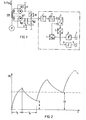
- the electronic overload protection contains a square element 1 for the voltage proportional to the stator current J 1 when the machine is running, a downstream analog-to-digital converter 2 for the formation of pulses with a loss-dependent frequency, a memory counter 3 with an up-count input for the said pulses and a down-count input for Pulses with temperature-dependent frequency at the output of an analog-to-digital converter 4, one of the temperature-dependent analog output signal to the output of Memory counter 3 connected digital-to-analog converter 5 is fed, the analog output signal is still supplied to a threshold element 6 of an overload release J and the threshold element 8 of a restart lock 9.
- the squaring element 1 is supplied with a voltage from a secondary rectifier GR1 from a secondary winding of a current transformer SW in the stator circuit of the machine M, which voltage occurs as a voltage drop across a resistor R H1 or RH 2 .
- the square element 1 is supplied with a voltage drop across the resistor R H1 which is proportional to the stator current J 1 in question.
- the machine starts up. there is an increased starting current J 1A in the stator and J 2A in the rotor (J 1A ⁇ J 2A ), which causes a higher power loss P 2A there than in the stator (P 1A ) due to the current displacement in the rotor, which is caused by an increased voltage drop on Input of the square element 1 is taken into account.
- a switch is made from resistor R H1 to a larger resistor R H2 by a changeover switch U, which is actuated by a threshold value element 10 from a stator-current-dependent direct voltage drop across a resistor R when a starting current exceeding three times the nominal current, for example, and that when the start-up is complete is switched back to Resistor R H1 is switched back.
- the switchable resistors R H1 , R H2 can be connected to both DC poles of the rectifier GR1 and connected to ground.
- the resistance values of R H1 and R H2 behave like C 1 / C Z > 1.
- the ratio C 1 / C 2 as an increase factor for the losses entered can be determined empirically by the current.
- the threshold value of the threshold element 10 is set by the resistor R to a value which is greater than three times the nominal current.
- the resistor R is fed via a rectifier GR2 from a separate secondary winding of the current transformer SW.
- Fig. 2 the rotor temperature is in the ordinate 2 and time is plotted on the abscissa.
- Each start-up process lasts in the run-up t N and in the run-out t A and increases the temperature from the cold or warm state by the same temperature stroke H.
- the restart lock 8, 9 has a minimum temperature increase of 2 x H selected as the blocking temperature after two starts so that the third start is still possible; the temperature limit is below 3 x H.
- the machine temperature rises with an e-function to almost below the tripping temperature in the event of overload.
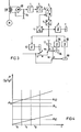
- a switchover from a first reclosure lock with a lower response temperature to a second reclosure lock with a higher response temperature can also be provided according to FIG. 3.
- the overload protection which is only thermally simulated for the stand-critical area, can work perfectly even with runner operation that is critical for the runner.
- the thermal simulation of the machine M is again carried out on the stator side by a current transformer SW for supplying a rectifier GR, to the rectifier poles of which a resistor R H is connected and connected to ground.
- the voltage drop occurring at the resistor R H which is proportional to the stator current, is again a square element 1 fed.
- the downstream circuit elements 2 to 7 correspond to those of Fig .. 1
- the first restart lock 8A, 9A speaks when the switch U '(contact position k) is not actuated until the blocking temperature is reached E1 on, so that three starts are possible when the machine is cold, since the closing contactor 11 remains live.
- the running machine exceeds the temperature N at nominal operation, the changeover temperature ⁇ u for the changeover switch U '.
- the warm machine is switched off and above the changeover temperature u switched on again, the second restart lock after the second start-up will bring its contact into position w when its blocking temperature i E2 is reached, whereby the switch-on contactor is de-energized and a further start is no longer possible.
- the temperatures reached by the machine are given in FIG. 4 in the ratio of the run-up current J H to the nominal current J N.
- the protection of the machine is carried out by a known starting current time monitoring, which can be omitted if a time constant corresponding to the stopping time is set while maintaining the permissible starting processes.
Landscapes
- Protection Of Generators And Motors (AREA)
- Control Of Ac Motors In General (AREA)
- Motor And Converter Starters (AREA)
Applications Claiming Priority (2)
| Application Number | Priority Date | Filing Date | Title |
|---|---|---|---|
| DE3237802 | 1982-10-12 | ||
| DE19823237802 DE3237802A1 (de) | 1982-10-12 | 1982-10-12 | Ueberlastschutz fuer eine elektrische maschine mit kurzschlusslaeufer gegen zu haeufiges anlassen |
Publications (2)
| Publication Number | Publication Date |
|---|---|
| EP0106255A2 true EP0106255A2 (fr) | 1984-04-25 |
| EP0106255A3 EP0106255A3 (fr) | 1987-02-04 |
Family
ID=6175538
Family Applications (1)
| Application Number | Title | Priority Date | Filing Date |
|---|---|---|---|
| EP83109866A Withdrawn EP0106255A3 (fr) | 1982-10-12 | 1983-10-03 | Protection contre le démarrage trop fréquent pour machine électrique à rotor court-circuité |
Country Status (2)
| Country | Link |
|---|---|
| EP (1) | EP0106255A3 (fr) |
| DE (1) | DE3237802A1 (fr) |
Cited By (2)
| Publication number | Priority date | Publication date | Assignee | Title |
|---|---|---|---|---|
| EP0332568A1 (fr) * | 1988-03-08 | 1989-09-13 | Siemens Aktiengesellschaft | Procédé de travail et circuit de commande pour surveiller le démarrage de moteurs électriques à haute tension avec démarrage asynchrone |
| EP0921618A3 (fr) * | 1997-12-05 | 2001-05-16 | Siemens Aktiengesellschaft | Circuit de commande d'un équipement électrique d'un entrainement |
Families Citing this family (2)
| Publication number | Priority date | Publication date | Assignee | Title |
|---|---|---|---|---|
| DE3623755A1 (de) * | 1986-07-15 | 1988-02-18 | Abus Kg | Einrichtung zur ueberlastsicherung von elektrischen antrieben |
| DE102006041642B3 (de) * | 2006-09-05 | 2008-04-10 | Siemens Ag | Verfahren zum elektronisch gesteuerten Überlastschutz eines elektrischen Gerätes und Vorrichtung zur Durchführung des Verfahrens |
Family Cites Families (5)
| Publication number | Priority date | Publication date | Assignee | Title |
|---|---|---|---|---|
| DE1163955B (de) * | 1962-06-06 | 1964-02-27 | Licentia Gmbh | UEberstrom-Schutzrelaissystem |
| DE2549850C3 (de) * | 1975-11-06 | 1980-07-24 | Siemens Ag, 1000 Berlin Und 8000 Muenchen | Thermische Überlastschutzeinrichtung für eine elektrische Maschine |
| CH623431A5 (en) * | 1978-02-03 | 1981-05-29 | Sprecher & Schuh Ag | Circuit for simulating the heat budget of an electrical apparatus or machine |
| GB1600392A (en) * | 1978-03-10 | 1981-10-14 | Allen J C H Schonken T D | Method of protecting electrical equipment and a protection relay for use in such a method |
| DE2939938C2 (de) * | 1979-09-28 | 1984-05-30 | Siemens AG, 1000 Berlin und 8000 München | Überlast-Schutzanordnung für eine elektrische Maschine |
-
1982
- 1982-10-12 DE DE19823237802 patent/DE3237802A1/de not_active Withdrawn
-
1983
- 1983-10-03 EP EP83109866A patent/EP0106255A3/fr not_active Withdrawn
Cited By (2)
| Publication number | Priority date | Publication date | Assignee | Title |
|---|---|---|---|---|
| EP0332568A1 (fr) * | 1988-03-08 | 1989-09-13 | Siemens Aktiengesellschaft | Procédé de travail et circuit de commande pour surveiller le démarrage de moteurs électriques à haute tension avec démarrage asynchrone |
| EP0921618A3 (fr) * | 1997-12-05 | 2001-05-16 | Siemens Aktiengesellschaft | Circuit de commande d'un équipement électrique d'un entrainement |
Also Published As
| Publication number | Publication date |
|---|---|
| DE3237802A1 (de) | 1984-04-12 |
| EP0106255A3 (fr) | 1987-02-04 |
Similar Documents
| Publication | Publication Date | Title |
|---|---|---|
| DE3124097C2 (fr) | ||
| DE19739780B4 (de) | Drehstrommotor | |
| DE2403903A1 (de) | Elektrische schutzanordnung fuer elektrisches energiesystem | |
| DE2354594A1 (de) | Schutzschaltung zum abschalten eines wechselstromverbrauchers beim auftreten von unregelmaessigkeiten in der stromversorgungsschaltung | |
| DE2617681A1 (de) | Geraet zur unterbrechung von fehlstroemen, insbesondere erdstroemen, in einem elektrischen netz | |
| DE3823922A1 (de) | Elektronische schaltvorrichtung mit leistungsueberwachung und integrierter absicherung fuer elektrische schaltkreise | |
| DE69812361T2 (de) | Festkörperüberstromrelais | |
| DE1438037B2 (de) | Schaltung zum ansteuern eines schalters in einem elektrischen versorgungsnetz | |
| DE2549850C3 (de) | Thermische Überlastschutzeinrichtung für eine elektrische Maschine | |
| DE1076245B (de) | Schutzeinrichtung fuer einen Generator | |
| DE3026125C2 (fr) | ||
| DE3237802A1 (de) | Ueberlastschutz fuer eine elektrische maschine mit kurzschlusslaeufer gegen zu haeufiges anlassen | |
| DE2552536A1 (de) | Elektrische schutzschalteinrichtung | |
| DE3228954C2 (de) | Schutzeinrichtung für Asynchron-Motoren | |
| EP0456172B1 (fr) | Relais de protection de moteur ou relais de surintensité unipolaire ou multipolaire | |
| DE3219199C2 (de) | Schaltungsanordnung zur Überwachung der Erwärmung von elektrisch betriebenen Motoren | |
| DE2822010C3 (de) | Schaltungsanordnung zum Überlastungsschutz für elektrische Anlagen | |
| DE3917478C1 (en) | Energy storage earth leakage protection switch - has summation current transformer with trip circuit connected across its sec. winding | |
| DE10018372C2 (de) | Schaltungsanordnung zur Einschaltstrombegrenzung für eine Stromversorgung | |
| DE2621277C3 (de) | Verfahren zum Schützen einer Fernsprechvermittlungsanlage gegen thermische Überlastung und Schaltungsanordnung zur Durchführung des Verfahrens | |
| DE2334135A1 (de) | Ueberstromlastabwurfeinrichtung | |
| DE2723164B2 (de) | Kurzschlußschutz für einen Resonanzshunt | |
| DE2659540A1 (de) | Schaltungsanordnung zur drehzahlregelung eines dreh- bzw. wechselstrommotors | |
| DE501739C (de) | Schutzvorrichtung fuer Mehrphasen-Asynchronmotoren | |
| DE2262711C3 (de) | Übers tromschutzrelais |
Legal Events
| Date | Code | Title | Description |
|---|---|---|---|
| PUAI | Public reference made under article 153(3) epc to a published international application that has entered the european phase |
Free format text: ORIGINAL CODE: 0009012 |
|
| AK | Designated contracting states |
Designated state(s): AT BE CH DE IT LI NL SE |
|
| 17P | Request for examination filed |
Effective date: 19841217 |
|
| PUAL | Search report despatched |
Free format text: ORIGINAL CODE: 0009013 |
|
| AK | Designated contracting states |
Kind code of ref document: A3 Designated state(s): AT BE CH DE IT LI NL SE |
|
| 17Q | First examination report despatched |
Effective date: 19880419 |
|
| STAA | Information on the status of an ep patent application or granted ep patent |
Free format text: STATUS: THE APPLICATION HAS BEEN WITHDRAWN |
|
| 18W | Application withdrawn |
Withdrawal date: 19880531 |
|
| RIN1 | Information on inventor provided before grant (corrected) |
Inventor name: NIMES, KARL, DIPL.-ING. |