EP0106261A1 - Procédé d'assemblage de deux pièces n'étant pas directement soudables l'une à l'autre - Google Patents
Procédé d'assemblage de deux pièces n'étant pas directement soudables l'une à l'autre Download PDFInfo
- Publication number
- EP0106261A1 EP0106261A1 EP83109894A EP83109894A EP0106261A1 EP 0106261 A1 EP0106261 A1 EP 0106261A1 EP 83109894 A EP83109894 A EP 83109894A EP 83109894 A EP83109894 A EP 83109894A EP 0106261 A1 EP0106261 A1 EP 0106261A1
- Authority
- EP
- European Patent Office
- Prior art keywords
- thin wall
- welded
- wall
- sheet
- welding
- Prior art date
- Legal status (The legal status is an assumption and is not a legal conclusion. Google has not performed a legal analysis and makes no representation as to the accuracy of the status listed.)
- Ceased
Links
- 238000000034 method Methods 0.000 title claims abstract description 34
- 239000000463 material Substances 0.000 claims abstract description 42
- 238000003466 welding Methods 0.000 claims abstract description 32
- 229910052751 metal Inorganic materials 0.000 claims abstract description 22
- 239000002184 metal Substances 0.000 claims abstract description 22
- 229910000831 Steel Inorganic materials 0.000 claims abstract description 14
- 239000010959 steel Substances 0.000 claims abstract description 14
- 229910052782 aluminium Inorganic materials 0.000 claims abstract description 13
- XAGFODPZIPBFFR-UHFFFAOYSA-N aluminium Chemical compound [Al] XAGFODPZIPBFFR-UHFFFAOYSA-N 0.000 claims abstract description 13
- 238000010438 heat treatment Methods 0.000 claims description 29
- 238000002844 melting Methods 0.000 claims description 13
- 230000008018 melting Effects 0.000 claims description 13
- 239000002245 particle Substances 0.000 claims description 5
- 230000001427 coherent effect Effects 0.000 claims 1
- 239000000945 filler Substances 0.000 abstract 4
- 239000004411 aluminium Substances 0.000 abstract 2
- 241000446313 Lamella Species 0.000 description 11
- 238000010521 absorption reaction Methods 0.000 description 5
- 239000000155 melt Substances 0.000 description 3
- XLYOFNOQVPJJNP-UHFFFAOYSA-N water Substances O XLYOFNOQVPJJNP-UHFFFAOYSA-N 0.000 description 3
- 239000000654 additive Substances 0.000 description 2
- 230000000996 additive effect Effects 0.000 description 2
- 239000000853 adhesive Substances 0.000 description 2
- 230000001070 adhesive effect Effects 0.000 description 2
- 239000007788 liquid Substances 0.000 description 2
- 239000012768 molten material Substances 0.000 description 2
- 238000003825 pressing Methods 0.000 description 2
- 238000005476 soldering Methods 0.000 description 2
- 239000000243 solution Substances 0.000 description 2
- 206010010904 Convulsion Diseases 0.000 description 1
- 241000237858 Gastropoda Species 0.000 description 1
- 239000003570 air Substances 0.000 description 1
- 239000012080 ambient air Substances 0.000 description 1
- 230000005540 biological transmission Effects 0.000 description 1
- 239000012267 brine Substances 0.000 description 1
- 238000005352 clarification Methods 0.000 description 1
- 230000036461 convulsion Effects 0.000 description 1
- 230000000694 effects Effects 0.000 description 1
- 230000017525 heat dissipation Effects 0.000 description 1
- 238000007373 indentation Methods 0.000 description 1
- 229910001092 metal group alloy Inorganic materials 0.000 description 1
- 239000002923 metal particle Substances 0.000 description 1
- 150000002739 metals Chemical class 0.000 description 1
- 238000004080 punching Methods 0.000 description 1
- HPALAKNZSZLMCH-UHFFFAOYSA-M sodium;chloride;hydrate Chemical compound O.[Na+].[Cl-] HPALAKNZSZLMCH-UHFFFAOYSA-M 0.000 description 1
- 239000007787 solid Substances 0.000 description 1
- 239000002699 waste material Substances 0.000 description 1
Images
Classifications
-
- F—MECHANICAL ENGINEERING; LIGHTING; HEATING; WEAPONS; BLASTING
- F28—HEAT EXCHANGE IN GENERAL
- F28F—DETAILS OF HEAT-EXCHANGE AND HEAT-TRANSFER APPARATUS, OF GENERAL APPLICATION
- F28F1/00—Tubular elements; Assemblies of tubular elements
- F28F1/10—Tubular elements and assemblies thereof with means for increasing heat-transfer area, e.g. with fins, with projections, with recesses
-
- B—PERFORMING OPERATIONS; TRANSPORTING
- B23—MACHINE TOOLS; METAL-WORKING NOT OTHERWISE PROVIDED FOR
- B23K—SOLDERING OR UNSOLDERING; WELDING; CLADDING OR PLATING BY SOLDERING OR WELDING; CUTTING BY APPLYING HEAT LOCALLY, e.g. FLAME CUTTING; WORKING BY LASER BEAM
- B23K11/00—Resistance welding; Severing by resistance heating
- B23K11/16—Resistance welding; Severing by resistance heating taking account of the properties of the material to be welded
- B23K11/20—Resistance welding; Severing by resistance heating taking account of the properties of the material to be welded of different metals
-
- F—MECHANICAL ENGINEERING; LIGHTING; HEATING; WEAPONS; BLASTING
- F28—HEAT EXCHANGE IN GENERAL
- F28F—DETAILS OF HEAT-EXCHANGE AND HEAT-TRANSFER APPARATUS, OF GENERAL APPLICATION
- F28F3/00—Plate-like or laminated elements; Assemblies of plate-like or laminated elements
- F28F3/02—Elements or assemblies thereof with means for increasing heat-transfer area, e.g. with fins, with recesses, with corrugations
- F28F3/025—Elements or assemblies thereof with means for increasing heat-transfer area, e.g. with fins, with recesses, with corrugations the means being corrugated, plate-like elements
-
- B—PERFORMING OPERATIONS; TRANSPORTING
- B23—MACHINE TOOLS; METAL-WORKING NOT OTHERWISE PROVIDED FOR
- B23K—SOLDERING OR UNSOLDERING; WELDING; CLADDING OR PLATING BY SOLDERING OR WELDING; CUTTING BY APPLYING HEAT LOCALLY, e.g. FLAME CUTTING; WORKING BY LASER BEAM
- B23K2101/00—Articles made by soldering, welding or cutting
- B23K2101/04—Tubular or hollow articles
- B23K2101/14—Heat exchangers
-
- F—MECHANICAL ENGINEERING; LIGHTING; HEATING; WEAPONS; BLASTING
- F28—HEAT EXCHANGE IN GENERAL
- F28F—DETAILS OF HEAT-EXCHANGE AND HEAT-TRANSFER APPARATUS, OF GENERAL APPLICATION
- F28F2275/00—Fastening; Joining
- F28F2275/08—Fastening; Joining by clamping or clipping
- F28F2275/085—Fastening; Joining by clamping or clipping with snap connection
Definitions
- the invention relates to a method for connecting a first part having a thin wall to a thin wall of a second part made of weldable material, wherein the first part consists of a material that is not weldable to the second part and wherein the thin wall of the first part abuts the thin wall of the second part.
- the welding of parts is a particularly economical process for connecting them.
- welding can only be used to a limited extent, since the prerequisite for this is that the materials can be welded to one another.
- Mainly the same or essentially the same metals and metal alloys can be welded to one another.
- aluminum and steel cannot be welded together.
- connection elements such as rivets or screws had to be used for such connection tasks.
- Other possible connection techniques, such as soldering and the adhesive technology are also disadvantageous and also expensive. A good heat transfer can be achieved with the soldering technique, but has to accept a very expensive process.
- Adhesive technology has decisive disadvantages in terms of heat transfer, maximum temperature stress and strength. The exploitation of the advantageous spot welding process was not easily possible.
- the invention is based on the object of proposing a method according to which parts which cannot be welded directly to one another can be connected to one another using a welding method.
- the melting point of the first part is lower than the melting point of the second part, this object is achieved in that additional material is arranged on the opposite side of the thin wall to the contact point, which is weldable to the material of the second part and that the additional material under Melting of the thin wall of the first part is welded to the thin wall of the second part by spot resistance welding, the heat necessary for the melting being generated by an electric current which is passed through electrodes which are used after the melting for the resistance pressure welding .
- This method has the advantage that it is not necessary to pre-process the first part. It is also achieved by melting the first part that the gap completely fills the space between the first part and the second part, which is a particularly close concern and thus e.g. results in a good heat-conducting connection.
- a method according to a further solution of the object of the invention can also be used if the melting point of the first part is higher than the melting point of the second part.
- This solution is characterized in that additional material in the form of at least one sheet is placed on the side of the thin wall opposite the contact point, which can be welded to the material of the second part and that the sheet through at least one hole previously made in the first part with bulging of the Sheet metal is pressed through by means of a welding electrode supplying a strong current and brought into contact with the second part and is welded to this part by resistance pressure welding, said electrode denting the sheet metal up to the edge of the hole in the first part.
- connections can be made in which the first part is in close contact with the second part.
- a good heat-conducting connection between steel and aluminum can be produced, the first part consisting of aluminum and the second part consisting of steel.
- the additional material in the form of a sheet, e.g. a sheet metal strip to apply (claims 3 and 4).
- a sheet of additional material can detect several welds (claim 4).
- the sheet causes a pressure effect of the thin wall of the first part on the thin wall of the second part also in the area outside the actual welding point.
- the additive material can also be applied in the form of small particles, e.g. in the form of metal chips or the like (claim 5). This process is particularly economical because waste material is recycled.
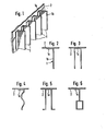
- the heat exchanger of Fig. 1 consists of several first parts 1 and a second part 2. It is assumed that the first parts 1 are made of aluminum and should give off heat to the environment and that the second part 2 is a steel heating plate, the heat is supplied in some way, e.g. by heated water, and should give up the heat to the lamellar first parts 1.
- the parts 1 are angular and have a short angle leg 1a and a long angle leg 1b. So that the heat from the heating plate 2 can be transferred as well as possible to the fins 1, it is necessary that the leg 1 a is pressed onto the heating plate 2 with as little space as possible. This can be achieved with the connection method, which will be considered below with reference to FIGS. 7, 8 and 9.
- the leg 1a of a lamella to be fastened is first provided with a row of holes 3.
- a sheet metal strip 4 made of additional material is placed on the top of the leg 1a and preferably has the same length as the slats 1.
- the strip 4 covers several holes 3.
- the strip 4 is preferably made of the same material as the wall of the heating plate 2, so for example from steel. In any case, the materials of the wall of the heating plate 2 and the metal strip 4 must be weldable to one another.
- welding electrodes 5 and 6 are attached. These are pressed firmly against each other, the sheet metal strip 4 being drawn into the holes 3 at the welding points. At the point of contact between the heating plate 2 and the strip 4, the material is heated so strongly by a high electric current that it melts, whereby a weld 7 is formed.
- the sheet metal strip 4 could also be provided with knobs which engage in the holes 3 before the welding electrodes are attached to the intended welding points. This would result in a form-fitting alignment of the metal strips on the perforations, but would have to provide a special operation for indenting the metal strip 4.
- the sheet metal strip 4 is pressed firmly against the leg 1a of the lamella to be fastened, as a result of which the lamella in turn is pressed firmly against the heating plate 2.
- the layer 8 below the wall need not be a solid layer, but e.g. from a liquid heating medium, e.g. Water.
- FIG. 8 illustrates a method in which a prior perforation of the leg 1a of the lamella 1 is not required.
- a sheet metal strip 4 is placed on the leg 1a, which is initially flat.
- the material of the lamella 1 melts and is displaced to the side by the pressing pressure of the electrode 5, so that the metal strip 4 can be pressed onto the heating plate 2.
- both the strip 4 and the heating plate 2 melt, creating a welding point 9.
- the molten material will also evaporate in part and escape at the side edges of the leg 1a. A portion of the molten material is distributed around the welding point 9, which creates a particularly good heat-conducting connection between the leg 1a and the heating plate 2.
- the material of the first part must have a lower melting point than the material of the heating plate 2. This is the case, for example, when the lamella 1 is made of aluminum and the heating plate 2 is made of steel, as is the case is assumed for the present case.
- FIG. 9 illustrates a method in which small particles are used as additional material which can be welded to the heating plate 2, for example punching slugs, chips, etc. material is sprinkled onto the leg 1a of the lamella at the welding point designated in total by 10.
- a welding current is passed through spot welding electrodes 5, 6, the material of the leg 1a melts until finally the scattered metal particles with the heating plate 2 ; come into contact. Then these particles are welded to the heating plate 2.
- the connection is made in that the particles remain partially embedded in the material of the leg 1a and, on the other hand, are welded to the heating plate 2, which creates a kind of toothing.
- the granular additive material 20 can be applied in coarse doses, e.g. in that it is sprinkled in the form of a strip onto the leg 1a to be fastened, and in that excess material is suctioned off after the welding process.
- FIG. 2 shows in cross section the lamella shape according to FIG. 1.
- FIGS. 3 to 6 show further possible lamella shapes. In all of these lamella shapes, however, there is a leg 1a which bears against the heating plate 2 and is connected to it in the manner described with reference to FIGS. 7 to 9.
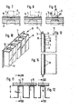
- the heater as a whole is designated H and has a heating plate 11 and a convection plate 12.
- the heater is composed of two shells 13, 14 and contains a cavity 15 for receiving a liquid heat transfer medium, e.g. Water.
- the heat transfer medium gives off part of its heat to the convection plate 12 via the shell 14.
- the convection plate rests on the heating plate 11 with heat absorption strips 16 and absorbs heat from the heating plate in this area. This heat is conducted by heat conduction in heat dissipation loops 17. Air sweeps along these and absorbs heat.
- the convection plate 12 is connected to the heating plate 11 in the manner which was explained above with reference to FIG. 7. This is shown in FIGS. 11 to 14 and will be considered below.
- the heat absorption strips 16 are provided with holes 3 which correspond to the holes 3 according to FIG. 7.
- a sheet metal strip 4 is placed, the width of which is equal to the width of the heat absorption strip. This state is also shown in FIG. 13. It can also be seen there that the heat absorption strips have a crimp 17 which projects from the heating plate 11.
- the sheet metal strip 4 has a corresponding crimp 18 into which the crimp 17 fits, as a result of which the entire convection sheet 12 is positively aligned and connected even before the welding relative to the heating plate 11.
- Indentations 19 are drawn into the flat sheet metal strips (with the exception of the convulsion 18), as is shown in FIG. 14 and corresponds to FIG. 7.
- the ratio of the height of the convection plate b to the thickness a of the convection plate can be chosen to be much larger than is possible when using steel plate for the convection plate.
- the invention was explained using the example of a heat exchanger.
- the heat-absorbing parts on this heat exchanger could also be the convector 12 or the fins 1.
- it could be a heat exchanger that absorbs heat from the ambient air and releases it to a brine that circulates within the plate 2 (FIG. 1) or 11 (FIGS. 10 to 14).
- the connection method according to the invention is also not restricted to use in a heat exchanger, but can be used wherever materials which cannot be welded to one another are to be connected to one another in an economical manner using spot welding.
Landscapes
- Engineering & Computer Science (AREA)
- Physics & Mathematics (AREA)
- Mechanical Engineering (AREA)
- Thermal Sciences (AREA)
- General Engineering & Computer Science (AREA)
- Geometry (AREA)
- Resistance Welding (AREA)
- Connection Of Plates (AREA)
Applications Claiming Priority (4)
| Application Number | Priority Date | Filing Date | Title |
|---|---|---|---|
| DE3237143 | 1982-10-07 | ||
| DE3237143 | 1982-10-07 | ||
| DE3303244A DE3303244C2 (de) | 1982-10-07 | 1983-02-01 | Verfahren zum Verbinden eines Aluminiumbleches mit einem Stahlblech |
| DE3303244 | 1983-02-01 |
Publications (1)
| Publication Number | Publication Date |
|---|---|
| EP0106261A1 true EP0106261A1 (fr) | 1984-04-25 |
Family
ID=25804977
Family Applications (1)
| Application Number | Title | Priority Date | Filing Date |
|---|---|---|---|
| EP83109894A Ceased EP0106261A1 (fr) | 1982-10-07 | 1983-10-04 | Procédé d'assemblage de deux pièces n'étant pas directement soudables l'une à l'autre |
Country Status (2)
| Country | Link |
|---|---|
| EP (1) | EP0106261A1 (fr) |
| DE (1) | DE3303244C2 (fr) |
Cited By (2)
| Publication number | Priority date | Publication date | Assignee | Title |
|---|---|---|---|---|
| EP0822025A1 (fr) * | 1996-08-03 | 1998-02-04 | Balcke-Dürr GmbH | Procédé de fabrication d'échangeurs de chaleur résistants à la corrosion |
| US6037559A (en) * | 1995-09-18 | 2000-03-14 | Honda Giken Kogyo Kabushiki Kaisha | Process for lap joining two kinds of metallic members having different melting points |
Families Citing this family (2)
| Publication number | Priority date | Publication date | Assignee | Title |
|---|---|---|---|---|
| DE19913436C1 (de) * | 1999-03-25 | 2000-12-14 | Erbsloeh Ag | Schweißverbindung von Bauteilen aus unterschiedlichen Werkstoffen |
| DE102010053608A1 (de) | 2010-12-07 | 2012-06-14 | Enova Technologie Gmbh | Schweißverbindung |
Citations (3)
| Publication number | Priority date | Publication date | Assignee | Title |
|---|---|---|---|---|
| AT256388B (de) * | 1963-09-19 | 1967-08-25 | Schlatter Ag | Radiator und Verfahren zur Herstellung desselben |
| DE2723072A1 (de) * | 1977-05-09 | 1978-11-23 | Baldwin Gegenheimer Corp | Verfahren zum verbinden von schichten durch verschweissen |
| US4343982A (en) * | 1981-03-23 | 1982-08-10 | Energy Development Associates, Inc. | Method of joining metal to graphite by spot welding |
Family Cites Families (4)
| Publication number | Priority date | Publication date | Assignee | Title |
|---|---|---|---|---|
| DE274559C (fr) * | ||||
| US1020991A (en) * | 1907-05-08 | 1912-03-26 | Laurence S Lachman | Process of electric welding. |
| DE970290C (de) * | 1950-09-15 | 1958-09-04 | Siemens Ag | Unter Verwendung von Zwischenlagen mit der Widerstands-, Punkt- und Rollennahtschweissmaschine hergestellte Schweissverbindung |
| DE1765077A1 (de) * | 1966-09-21 | 1971-07-01 | Dr Becker Alfred Otto | Verfahren zum Widerstandsschweissen von beschichteten Blechen und Maschinen dazu |
-
1983
- 1983-02-01 DE DE3303244A patent/DE3303244C2/de not_active Expired
- 1983-10-04 EP EP83109894A patent/EP0106261A1/fr not_active Ceased
Patent Citations (3)
| Publication number | Priority date | Publication date | Assignee | Title |
|---|---|---|---|---|
| AT256388B (de) * | 1963-09-19 | 1967-08-25 | Schlatter Ag | Radiator und Verfahren zur Herstellung desselben |
| DE2723072A1 (de) * | 1977-05-09 | 1978-11-23 | Baldwin Gegenheimer Corp | Verfahren zum verbinden von schichten durch verschweissen |
| US4343982A (en) * | 1981-03-23 | 1982-08-10 | Energy Development Associates, Inc. | Method of joining metal to graphite by spot welding |
Non-Patent Citations (3)
| Title |
|---|
| Patent Abstracts of Japan Band 4, Nr. 161, 11. November 1980 Seite 75 M 40 & JP-A-55-110893 * |
| SCHWEISSTECHNIK, Band 22, Heft 8, 1972, DDR-Berlin * |
| SCHWEISSTECHNIK, Band 22, Heft 8, 1972, DDR-Berlin J. SZYMANSKI "Punktschweissen aluminierter Bleche im Stahlbau", Seiten 361-363 * |
Cited By (3)
| Publication number | Priority date | Publication date | Assignee | Title |
|---|---|---|---|---|
| US6037559A (en) * | 1995-09-18 | 2000-03-14 | Honda Giken Kogyo Kabushiki Kaisha | Process for lap joining two kinds of metallic members having different melting points |
| EP0865860A4 (fr) * | 1995-09-18 | 2001-08-16 | Honda Motor Co Ltd | Procede de jointure par recouvrement de deux elements metalliques de type different et ayant des points de fusion differents |
| EP0822025A1 (fr) * | 1996-08-03 | 1998-02-04 | Balcke-Dürr GmbH | Procédé de fabrication d'échangeurs de chaleur résistants à la corrosion |
Also Published As
| Publication number | Publication date |
|---|---|
| DE3303244A1 (de) | 1984-04-12 |
| DE3303244C2 (de) | 1987-04-23 |
Similar Documents
| Publication | Publication Date | Title |
|---|---|---|
| DE102007056750B4 (de) | Montageanordnung für eine Elektronische Steuervorrichtung und Steuervorrichtung damit | |
| DE2825831A1 (de) | Verfahren zum verbinden eines metallischen teils mit einem nichtmetallischen teil | |
| DE2810275A1 (de) | Waermetauscher | |
| DE2508114A1 (de) | Reibungsteil und verfahren zu seinem zusammenbau | |
| DE102016212622A1 (de) | Verfahren zum Fügen von Bauteilen | |
| EP0106262B1 (fr) | Echangeur thermique en particulier radiateur | |
| EP1766734B1 (fr) | Procede de liaison d'au moins un conducteur a un element de contact | |
| DE102005001435A1 (de) | Absorber für einen thermischen Solarkollektor und Verfahren zum Herstellen eines derartigen Absorbers | |
| EP0106261A1 (fr) | Procédé d'assemblage de deux pièces n'étant pas directement soudables l'une à l'autre | |
| DE102017206925A1 (de) | Verfahren zum Erzeugen einer Diffusionslötverbindung | |
| DE60219134T2 (de) | Schweißanlage mit inandergreifenden leitenden Endabschnitten | |
| EP0822025B1 (fr) | Procédé de fabrication d'échangeurs de chaleur résistants à la corrosion | |
| EP0191300B1 (fr) | Procédé de soudage par résistance pour souder ou braser des métaux métastables | |
| DE10359564B4 (de) | Verfahren zum Verbinden von Bauteilen | |
| EP0102927A1 (fr) | Groupe de bossages et procédé pour soudages multiples par bossages | |
| DE3510779A1 (de) | Verfahren zum verbinden von zwei oder mehr blechen | |
| DE19815476C1 (de) | Verfahren zum Verschweißen eines Doppellagenbleches mit einem Fügeblech | |
| DE2834767B2 (de) | Wärmetauscher, insbesondere für Kraftfahrzeuge und Verfahren zu dessen Herstellung | |
| DE102004055083B4 (de) | Schweißteil für das Verschweißen mittels einer Kehlnaht und elektrische Baueinheit | |
| DE102023001903B4 (de) | Verfahren zum Verbinden von mindestens zwei Bauteilen | |
| DE10204474A1 (de) | Spannvorrichtung und Verfahren zum Laserschweißen beschichteter Bleche | |
| DE102017213586A1 (de) | Verfahren und Verbindungen zum Schweißen von unähnlichen Blechmaterialien | |
| DE3924162A1 (de) | Verfahren zum abbrennstumpfschweissen von hochgekohlten werkstoffen, insbesondere gusseisen mit kugelgraphit | |
| DE102004012367A1 (de) | Behälter und Verfahren zum Herstellen eines Behälters | |
| DE3331619C2 (fr) |
Legal Events
| Date | Code | Title | Description |
|---|---|---|---|
| PUAI | Public reference made under article 153(3) epc to a published international application that has entered the european phase |
Free format text: ORIGINAL CODE: 0009012 |
|
| AK | Designated contracting states |
Designated state(s): AT BE CH DE FR GB IT LI NL SE |
|
| 17P | Request for examination filed |
Effective date: 19840917 |
|
| STAA | Information on the status of an ep patent application or granted ep patent |
Free format text: STATUS: THE APPLICATION HAS BEEN REFUSED |
|
| 18R | Application refused |
Effective date: 19870822 |
|
| RIN1 | Information on inventor provided before grant (corrected) |
Inventor name: MEIKE, KLAUS |