EP0106331A2 - Process and apparatus for separating coarse particles from a liquid - Google Patents
Process and apparatus for separating coarse particles from a liquid Download PDFInfo
- Publication number
- EP0106331A2 EP0106331A2 EP83110256A EP83110256A EP0106331A2 EP 0106331 A2 EP0106331 A2 EP 0106331A2 EP 83110256 A EP83110256 A EP 83110256A EP 83110256 A EP83110256 A EP 83110256A EP 0106331 A2 EP0106331 A2 EP 0106331A2
- Authority
- EP
- European Patent Office
- Prior art keywords
- liquid
- screen cloth
- nozzle
- container
- air
- Prior art date
- Legal status (The legal status is an assumption and is not a legal conclusion. Google has not performed a legal analysis and makes no representation as to the accuracy of the status listed.)
- Ceased
Links
Images

Classifications
-
- D—TEXTILES; PAPER
- D21—PAPER-MAKING; PRODUCTION OF CELLULOSE
- D21D—TREATMENT OF THE MATERIALS BEFORE PASSING TO THE PAPER-MAKING MACHINE
- D21D5/00—Purification of the pulp suspension by mechanical means; Apparatus therefor
- D21D5/02—Straining or screening the pulp
- D21D5/04—Flat screens
-
- B—PERFORMING OPERATIONS; TRANSPORTING
- B01—PHYSICAL OR CHEMICAL PROCESSES OR APPARATUS IN GENERAL
- B01D—SEPARATION
- B01D29/00—Filters with filtering elements stationary during filtration, e.g. pressure or suction filters, not covered by groups B01D24/00 - B01D27/00; Filtering elements therefor
- B01D29/01—Filters with filtering elements stationary during filtration, e.g. pressure or suction filters, not covered by groups B01D24/00 - B01D27/00; Filtering elements therefor with flat filtering elements
-
- B—PERFORMING OPERATIONS; TRANSPORTING
- B01—PHYSICAL OR CHEMICAL PROCESSES OR APPARATUS IN GENERAL
- B01D—SEPARATION
- B01D29/00—Filters with filtering elements stationary during filtration, e.g. pressure or suction filters, not covered by groups B01D24/00 - B01D27/00; Filtering elements therefor
- B01D29/88—Filters with filtering elements stationary during filtration, e.g. pressure or suction filters, not covered by groups B01D24/00 - B01D27/00; Filtering elements therefor having feed or discharge devices
- B01D29/90—Filters with filtering elements stationary during filtration, e.g. pressure or suction filters, not covered by groups B01D24/00 - B01D27/00; Filtering elements therefor having feed or discharge devices for feeding
- B01D29/902—Filters with filtering elements stationary during filtration, e.g. pressure or suction filters, not covered by groups B01D24/00 - B01D27/00; Filtering elements therefor having feed or discharge devices for feeding containing fixed liquid displacement elements or cores
-
- B—PERFORMING OPERATIONS; TRANSPORTING
- B01—PHYSICAL OR CHEMICAL PROCESSES OR APPARATUS IN GENERAL
- B01D—SEPARATION
- B01D29/00—Filters with filtering elements stationary during filtration, e.g. pressure or suction filters, not covered by groups B01D24/00 - B01D27/00; Filtering elements therefor
- B01D29/88—Filters with filtering elements stationary during filtration, e.g. pressure or suction filters, not covered by groups B01D24/00 - B01D27/00; Filtering elements therefor having feed or discharge devices
- B01D29/90—Filters with filtering elements stationary during filtration, e.g. pressure or suction filters, not covered by groups B01D24/00 - B01D27/00; Filtering elements therefor having feed or discharge devices for feeding
- B01D29/904—Filters with filtering elements stationary during filtration, e.g. pressure or suction filters, not covered by groups B01D24/00 - B01D27/00; Filtering elements therefor having feed or discharge devices for feeding directing the mixture to be filtered on the filtering element in a manner to clean the filter continuously
Definitions
- the invention relates to a method for separating coarse particles from a liquid according to the preamble of claim 1 and an apparatus for performing the method, which has the features listed in the preamble of claim 4.
- a liquid containing coarse and fine particles e.g. Water
- these particles include from coarse and fine fibers.
- the liquid comes from washing machines and contains fine fibers, lint and the like. as well as coarser components.
- the liquid level in the container is kept at a constant level below the nozzle, so that it is in a closed air space between the screen cloth and the liquid surface.
- the liquid level is kept constant by means of an overflow and this liquid must then be cleaned of the coarser particles before it can be used further.
- additional energy has to be used in the treatment of this liquid, the amount of which is 15-30% of the amount conveyed by the pump.
- the invention has for its object to largely avoid these disadvantages of the known devices, which is achieved according to the invention with the means that form the characterizing features of claim 1 and claim 4.
- Advantageous embodiments of the method and the device form the subject of the subclaims.
- the liquid can only flow out of the container through the screen cloth.
- the liquid passing through the screen cloth in one time unit is thus equal to the total liquid conveyed by the pump in the unit time, so that the disadvantages associated with the known devices with the partial flow flowing off via the overflow are completely avoided.
- the coarse particles slowly sink to the bottom of the container and accumulate there, so that they can be removed from the container quickly and easily from time to time by placing one on the bottom of the container Separation valve is opened for a short time.
- washing systems considerable advantages are achieved since no hot water flows out of the container, but rather all of the water flows through the screen cloth and can thus give off its heat to the heat exchanger.
- the suction line of the pump is advantageously connected to an air line in which a regulating valve is arranged, so that more or less air can be sucked into the liquid conveyed by the pump.
- This additional air then relaxes in the air space underneath the screen cloth and influences the air pressure in this space and thus also the level of the liquid in the container.
- the liquid conveyed by the pump usually contains a small amount of air, which also relaxes during the spraying process and thus additionally increases the air pressure in the space under the screen cloth.
- a guide cone is arranged at a distance from the nozzle, so that the preferably hollow conical liquid jet passes through a liquid layer which is located in the gap between the nozzle and the lower boundary of the guide cone. The formation of the liquid jet is thus maintained by the guide cone up to its upper end and beyond until it hits the screen cloth.
- the level of the container liquid thus extends up to a certain height on the outer surface of the guide cone. Practical tests have shown that with the arrangement of this guide cone i.a. stable operation with a constant liquid level is achieved.
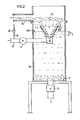
- the liquid, the coarse and fine particles such as Contains fibers of different sizes, the container 14 is fed through a line 10.
- the liquid usually also contains a certain amount of air.
- a pump 11 is arranged in line 10, the delivery pressure of which can be regulated in the usual way.
- the pump 11 conveys the liquid to a nozzle 12 of a known embodiment, which sprays the liquid into a conical jet 13, which should expediently be hollow.
- the nozzle 12 is arranged in a vertical container 14 which has an intermediate wall in the form of a screen cloth 15 in its upper region.
- the mesh size of the screen cloth can be in a range of 10-100 ⁇ m and is usually in the lower range.
- An outlet connection 16 is arranged above the screen cloth 15, which is penetrated by the liquid together with fine particles.
- the liquid is sprayed upwards against the underside of the screen cloth 15, the coarser particles impinging on the screen cloth and falling down from it in the container, in whose liquid they sink down and collect on the bottom 17 thereof.
- the liquid is held in the container 14 at a substantially constant height 18, the liquid level being at a distance H above the outlet opening of the nozzle 12 shown in FIG. 1, so that the conical liquid jet passes through a liquid layer of appropriate thickness without its conical one Losing shape.
- the liquid located in the vicinity of the nozzle 12 is sucked into the liquid jet so that a larger amount of liquid is sprayed against the screen cloth 15 than is conveyed by the pump 11. For example, if the pump delivers 100 liters per minute, 120 liters per minute can be sprayed against the screen cloth 15, with 100 liters per minute flowing through the screen cloth 15 and the outlet port 16, while 20 liters per minute flow back from the screen cloth and mix with the liquid jet of the nozzle 12 and are sprayed again against the screen cloth 15. The larger amount of liquid sprayed against the screen cloth 15 thus leads to more stable and quieter operating conditions.
- the rough adjustment of the liquid level is carried out by regulating the pump pressure.
- a fine adjustment is made by introducing more or less additional air into the suction line of the pump 11.
- the suction line 10 of the pump 11 is connected to an air line 19, so that air 19 can be sucked in through this line, the desired amount of which can be finely adjusted by means of the regulating valve 20.
- a guide surface 22 is provided in the container 14 in the form of a truncated cone, the cone angle of which is approximately the same as that of the liquid jet sprayed by the nozzle 12.
- This conical guide surface is arranged coaxially with the nozzle 12 above it with its conically tapering end pointing downwards, so that the conical liquid jet enters this guide cone and is guided within this guide cone until it flows past the upper end of the guide cone onto the screen cloth 15 hits.
- the upper end of the guide cone is located approximately halfway between the nozzle 12 and the screen cloth 15 or somewhat higher.
- the liquid level 18A in the container 14 is somewhat higher than in the exemplary embodiment shown in FIG. 1, since it is at a greater height than the gap between the nozzle 12 and the guide cone 22. In this case, the liquid level is at a height H2 above the nozzle opening.
- An outlet valve 21 is provided on the bottom of the container 14 in order to be able to pull off the coarse particles which have accumulated on the bottom of the container from time to time. In certain cases it is sufficient to remove the coarse particles only once during 24 hours.
- the branched-off liquid flow in the previously known devices, can be up to approximately 15-30% of the total flow. In water purification systems, for example, this means that the branched-off water flow also has to be cleaned in order to achieve a perfect cleaning effect. However, this is not necessary in the device according to the invention, since 100% of the total liquid flow passes through the screen cloth 15 and flows out through the outlet connection 16. For a given current passing through the screen cloth 15, the method and the device according to the invention can use a pump with a lower delivery rate than is required in the known devices.
Landscapes
- Chemical & Material Sciences (AREA)
- Chemical Kinetics & Catalysis (AREA)
- Engineering & Computer Science (AREA)
- Mechanical Engineering (AREA)
- Treatment Of Fiber Materials (AREA)
- Separation Of Solids By Using Liquids Or Pneumatic Power (AREA)
- Application Of Or Painting With Fluid Materials (AREA)
- Paper (AREA)
Abstract
Um beispielsweise in Waschanlagen u.dgl. der Zellulose-Industrie grobe Partikel aus einer Flüssigkeit, z.B. Wasser, abzuscheiden, ist es üblich, einen senkrechten Behälter (14) zu verwenden, in dem einer Düse (12) von einer Pumpe (11) Flüssigkeit zugeführt wird, die von der Düse (12) in Gestalt eines konischen Strahls (13) nach oben gegen die Unterseite eines Siebtuches (15) zersprüht wird. Oberhalb des Siebtuches (15) ist ein Auslaß (16) für die gereinigte Flüssigkeit vorgesehen, während auf das Siebtuch (15) auftreffende grobe Partikel zurückfallen und auf den Boden (17) des Behälters (14) absinken. Gemäß der Erfindung durchsetzt der gesamte, von der Pumpe (11) geförderte und von der Düse (12) zersprühte Flüssigkeitsstrom das Siebtuch (15) und fließt durch einen oberhalb des Siebtuches (15) angeordneten Auslaß (16) ab.
Description
Die Erfindung betrifft ein Verfahren zum Abtrennen grober Partikel von einer Flüssigkeit gemäß dem Gattungsbegriff des Anspruchs 1 sowie eine Vorrichtung zur Durchführung des Verfahrens, die die im Gattungsbegriff des Anspruchs 4 aufgeführten Merkmale aufweist.The invention relates to a method for separating coarse particles from a liquid according to the preamble of claim 1 and an apparatus for performing the method, which has the features listed in the preamble of claim 4.
Vorrichtungen dieser Art sind aus der US-PS 3 789 978 und der US-PS 4 153 543 bekannt.Devices of this type are known from US Pat. No. 3,789,978 and US Pat. No. 4,153,543.
Bei diesen bekannten Vorrichtungen wird eine grobe und feine Partikel enthaltende Flüssigkeit, z.B. Wasser, von einer in einem senkrechten Behälter angeordneten Düse in einem kegelförmigen Strahl gegen die Unterseite eines horizontal angeordneten Siebtuches zersprüht. Bei Anlagen der Zellulose-Industrie bestehen diese Partikel u.a. aus groben und feinen Fasern. In Waschanlagen kommt die Flüssigkeit von Waschmaschinen und enthält feine Fasern, Fusseln u.dgl. sowie gröbere Bestandteile.In these known devices, a liquid containing coarse and fine particles, e.g. Water, sprayed from a nozzle arranged in a vertical container in a conical jet against the underside of a horizontally arranged screen cloth. In plants in the cellulose industry, these particles include from coarse and fine fibers. In washing systems, the liquid comes from washing machines and contains fine fibers, lint and the like. as well as coarser components.
Bei diesen vorbekannten Vorrichtungen wird der Flüssigkeitsspiegel in dem Behälter in einem konstanten Niveau unterhalb der Düse gehalten, so daß diese sich in einem geschlossenen Luftraum zwischen dem Siebtuch und der Flüssigkeitsoberfläche befindet. Bei diesen bekannten Vorrichtungen wird der Flüssigkeitsspiegel mittels eines Überlaufs konstant gehalten und diese Flüssigkeit muß dann von den gröberen Partikeln gereinigt werden, ehe sie weiter verwendet werden kann. In der Zellulose-Industrie muß zum Abscheiden dieser groben Partikel zusätzliche Energie bei der Behandlung dieser Flüssigkeit aufgewandt werden, deren Menge 15-30% der von der Pumpe geförderten Menge beträgt.In these known devices, the liquid level in the container is kept at a constant level below the nozzle, so that it is in a closed air space between the screen cloth and the liquid surface. In these known devices, the liquid level is kept constant by means of an overflow and this liquid must then be cleaned of the coarser particles before it can be used further. In the cellulose industry, to separate these coarse particles, additional energy has to be used in the treatment of this liquid, the amount of which is 15-30% of the amount conveyed by the pump.
Diese Unterteilung des gesamten Flusses weist beträchtliche Nachteile auf.This subdivision of the entire river has considerable disadvantages.
Bei Waschanlagen tritt noch der weitere Nachteil hinzu, daß das Abscheiden mittels des Überlaufs gleichzeitig beträchtliche Wärmeverluste mit sich bringt.In washing systems there is the further disadvantage that the separation by means of the overflow also entails considerable heat losses.
Der Erfindung liegt die Aufgabe zugrunde, diese Nachteile der bekannten Vorrichtungen weitgehend zu vermeiden, was gemäß der Erfindung mit den Mitteln erreicht wird, die die kennzeichnenden Merkmale des Anspruchs 1 und des Anspruchs 4 bilden. Vorteilhafte Ausgestaltungen des Verfahrens und der Vorrichtung bilden den Gegenstand der Unteransprüche.The invention has for its object to largely avoid these disadvantages of the known devices, which is achieved according to the invention with the means that form the characterizing features of claim 1 and claim 4. Advantageous embodiments of the method and the device form the subject of the subclaims.
Bei dem erfindungsgemäßen Verfahren und der zur Durchführung dieses Verfahrens dienenden Vorrichtung kann die Flüssigkeit von dem Behälter nur durch das Siebtuch abfließen. Die das Siebtuch in einer Zeiteinheit durchsetzende Flüssigkeit ist somit gleich der in der Zeiteinheit von der Pumpe geförderten Gesamtflüssigkeit, so daß die bei den bekannten Vorrichtungen mit dem über den Überlauf abfließenden Teilstrom verbundenen Nachteile gänzlich vermieden werden. Bei dem erfindungsgemäßen Verfahren und der erfindungsgemäßen Vorrichtung sinken die groben Partikel langsam zum Boden des Behälters ab und sammeln sich dort an, so daß sie von Zeit zu Zeit in einfacher Weise und rasch aus dem Behälter entfernt werden können, indem ein am Boden des Behälters angeordnetes Abscheideventil kurze Zeit geöffnet wird. Bei Waschanlagen werden so beträchtliche Vorteile erzielt, da kein heißes Wasser aus dem Behälter abfließt, das gesamte Wasser vielmehr durch das Siebtuch hindurchströmt und somit seine Wärme an Wärmetauscher abgeben kann. Der Einsatz der erfindungsgemäßen Vorrichtung in Waschanlagen bringt u.a. noch den Vorteil mit sich, daß die BOD- und die COD-Gehalte des das Siebtuch durchströmenden Wassers auf mindestens 60% gesenkt werden können. Dieser Verteil wird insbesondere dann erzielt, wenn der Flüssigkeitsspiegel in dem Behälter auf einer konstanten Höhe oberhalb der Düse gehalten wird. Da das unkontrollierte Einleiten solchen verunreinigten Wassers in öffentliche Gewässer in verschiedenen Ländern unter Strafe steht, bedeutet eine Verringerung dieser Verunreinigungen niedrigere Strafen und somit geringere Betriebskosten.In the method according to the invention and the device used to carry out this method, the liquid can only flow out of the container through the screen cloth. The liquid passing through the screen cloth in one time unit is thus equal to the total liquid conveyed by the pump in the unit time, so that the disadvantages associated with the known devices with the partial flow flowing off via the overflow are completely avoided. In the method and the device according to the invention, the coarse particles slowly sink to the bottom of the container and accumulate there, so that they can be removed from the container quickly and easily from time to time by placing one on the bottom of the container Separation valve is opened for a short time. In washing systems, considerable advantages are achieved since no hot water flows out of the container, but rather all of the water flows through the screen cloth and can thus give off its heat to the heat exchanger. The use of the device according to the invention in car washes Among other things, there is the advantage that the BOD and COD contents of the water flowing through the screen cloth can be reduced to at least 60%. This distribution is achieved in particular when the liquid level in the container is kept at a constant level above the nozzle. Since the uncontrolled discharge of such contaminated water into public waters in various countries is punishable, reducing these contaminants means lower penalties and thus lower operating costs.
Um den Flüssigkeitsspiegel oberhalb der Düse fein einstellen zu können, ist die Saugleitung der Pumpe vorteilhafterweise mit einer Luftleitung verbunden, in der ein Regulierventil angeordnet ist, so daß mehr oder weniger Luft in die von der Pumpe geförderte Flüssigkeit eingesaugt werden kann. Diese zusätzliche Luft entspannt sich dann in dem unterhalb des Siebtuches gelegenen Luftraum und beeinflußt den Luftdruck in diesem Raum und damit auch die Höhe des Flüssigkeitsspiegels in dem Behälter. Die von der Pumpe geförderte Flüssigkeit enthält üblicherweise eine kleine Menge Luft, die sich ebenfalls beim Sprühvorgang entspannt und somit den Luftdruck in dem unter dem Siebtuch gelegenen Raum zusätzlich erhöht.In order to be able to finely adjust the liquid level above the nozzle, the suction line of the pump is advantageously connected to an air line in which a regulating valve is arranged, so that more or less air can be sucked into the liquid conveyed by the pump. This additional air then relaxes in the air space underneath the screen cloth and influences the air pressure in this space and thus also the level of the liquid in the container. The liquid conveyed by the pump usually contains a small amount of air, which also relaxes during the spraying process and thus additionally increases the air pressure in the space under the screen cloth.
Um die Betriebsbedingungen noch zu verbessern, ist oberhalb der Düse im Abstand von dieser ein Leitkonus angeordnet, so daß der vorzugsweise hohle konische Flüssigkeitsstrahl eine Flüssigkeitsschicht durchsetzt, die sich in dem Spalt zwischen der Düse und der unteren Begrenzung des Leitkonus befindet. Die Ausbildung des Flüssigkeitsstrahls wird so durch den Leitkonus bis zu dessen oberem Ende und darüber hinaus bis zum Auftreffen auf das Siebtuch aufrechterhalten.In order to further improve the operating conditions, a guide cone is arranged at a distance from the nozzle, so that the preferably hollow conical liquid jet passes through a liquid layer which is located in the gap between the nozzle and the lower boundary of the guide cone. The formation of the liquid jet is thus maintained by the guide cone up to its upper end and beyond until it hits the screen cloth.
Der Spiegel der Behälterflüssigkeit reicht somit an der Außenfläche des Leitkonus bis zu einer gewissen Höhe herauf. Praktische Versuche haben gezeigt, daß mit der Anordnung dieses Leitkonus u.a. ein stabiler Betrieb mit einem gleichbleibenden Flüssigkeitsspiegel erreicht wird.The level of the container liquid thus extends up to a certain height on the outer surface of the guide cone. Practical tests have shown that with the arrangement of this guide cone i.a. stable operation with a constant liquid level is achieved.
In der Zeichnung sind in schematischer Weise zwei Ausführungsbeispiele der erfindungsgemäßen Vorrichtung dargestellt.In the drawing, two exemplary embodiments of the device according to the invention are shown in a schematic manner.
- Fig. 1 zeigt einen senkrechten Schnitt durch die Vorrichtung gemäß einem 1. Ausführungsbeispiel;Fig. 1 shows a vertical section through the device according to a first embodiment;
- Fig. 2 zeigt denselben Schnitt durch ein zweites Ausführungsbeispiel, das sich von dem in Fig. 1 dargestellten Ausführungsbeispiel durch die Anordnung eines Leitkonus oberhalb der Düse unterscheidet.Fig. 2 shows the same section through a second embodiment, which differs from the embodiment shown in Fig. 1 by the arrangement of a guide cone above the nozzle.
Die Flüssigkeit, die grobe und feine Partikel wie z.B. Fasern unterschiedlicher Größe enthält, wird dem Behälter 14 durch eine Leitung 10 zugeführt. Die Flüssigkeit enthält üblicherweise auch eine gewisse Luftmenge. In der Leitung 10 ist eine Pumpe 11 angeordnet, deren Förderdruck in üblicher Weise regulierbar ist. Die'Pumpe 11 fördert die Flüssigkeit zu einer Düse 12 bekannter Ausführungsform, die die Flüssigkeit in einen konischen Strahl 13 zersprüht, der zweckmäßigerweise hohl ausgebildet sein soll.The liquid, the coarse and fine particles such as Contains fibers of different sizes, the
Die Düse 12 ist in einem senkrechten Behälter 14 angeordnet, der in seinem oberen Bereich eine Zwischenwand in Gestalt eines Siebtuches 15 aufweist. Die Maschenweite des Siebtuches kann in einem Bereich von 10-100 µm liegen und liegt üblicherweise in dessen unterem Bereich.The
Oberhalb des Siebtuches 15, das von der Flüssigkeit zusammen mit feinen Partikeln durchsetzt wird, ist ein Auslaßstutzen 16 angeordnet.An
Gemäß der Erfindung strömt die gesamte von der Pumpe 11 geförderte Flüssigkeit durch das Siebtuch 15 und den Auslaßstutzen 16.According to the invention, all of the liquid conveyed by the
Die Flüssigkeit wird nach oben gegen die Unterseite des Siebtuches 15 zersprüht, wobei die gröberen Partikel auf das Siebtuch auftreffen und von diesem im Behälter nach unten fallen, in dessen Flüssigkeit sie nach unten sinken und sich an dessen Boden 17 ansammeln.The liquid is sprayed upwards against the underside of the
Die Flüssigkeit wird in dem Behälter 14 auf einer im wesentlichen konstanten Höhe 18 gehalten, wobei der Flüssigkeitsspiegel in einem Abstand H oberhalb der Auslaßöffnung der in Fig. 1 gezeichneten Düse 12 liegt, so daß der konische Flüssigkeitsstrahl eine Flüssigkeitsschicht entsprechender Dicke durchsetzt, ohne seine konische Gestalt zu verlieren. Die in der Nähe der Düse 12 befindliche Flüssigkeit wird so in den Flüssigkeitsstrahl hineingesaugt, so daß eine größere Flüssigkeitsmenge gegen das Siebtuch 15 zersprüht wird, als von der Pumpe 11 gefördert wird. Wenn die Pumpe beispielsweise 100 Liter je Minute fördert, so können 120 Liter je Minute gegen das Siebtuch 15 zersprüht werden, wobei 100 Liter je Minute durch das Siebtuch 15 und den Auslaßstutzen 16 hindurchströmen, während 20 Liter je Minute von dem Siebtuch nach unten zurückfließen und sich mit dem Flüssigkeitsstrahl der Düse 12 vermischen und so erneut gegen das Siebtuch 15 gesprüht werden. Die größere gegen das Siebtuch 15 gesprühte Flüssigkeitsmenge führt so zu stabileren und ruhigeren Betriebsbedingungen.The liquid is held in the
Bei der Vorrichtung nach Fig. 1 erfolgt die Grobeinstellung des Flüssigkeitsspiegels durch Regulierung des Pumpendrucks. Eine Feineinstellung erfolgt dadurch, daß mehr oder weniger Zusatzluft in die Saugleitung der Pumpe 11 eingeleitet wird. Zu diesem Zweck ist die Saugleitung 10 der Pumpe 11 mit einer Luftleitung 19 verbunden, so daß durch diese Leitung 19 Luft angesaugt werden kann, deren gewünschte Menge mittels des Regulierventils 20 fein eingestellt werden kann. Grundsätzlich wäre es auch möglich, eine einstellbare Luftmenge unmittelbar in den Luftraum zwischen dem Siebtuch 15 und dem Flüssigkeitsspiegel 18 einzuleiten, dies würde jedoch eine Druckluftzufuhr erforderlich machen, die etwas aufwendiger wäre als eine Anordnung, bei der in einfacher Weise Luft aus der Leitung 19 angesaugt wird.In the device according to FIG. 1, the rough adjustment of the liquid level is carried out by regulating the pump pressure. A fine adjustment is made by introducing more or less additional air into the suction line of the
Bei dem in Fig. 2 dargestellten Ausführungsbeispiel ist in dem Behälter 14 eine Leitfläche 22 in Gestalt eines Kegelstumpfmantels vorgesehen, dessen Kegelwinkel näherungsweise derselbe ist wie der des von der Düse 12 zersprühten Flüssigkeitsstrahls. Diese konische Leitfläche ist koaxial mit der Düse 12 oberhalb dieser mit ihrem konisch sich verjüngenden Ende nach unten weisend angeordnet, so daß der konische Flüssigkeitsstrahl in diesen Leitkonus eintritt und innerhalb dieses Leitkonus geführt wird, bis er an dem oberen Ende des Leitkonus vorbeiströmend auf das Siebtuch 15 auftrifft.In the embodiment shown in FIG. 2, a guide surface 22 is provided in the
Zwischen dem unteren Ende des Leitkonus 22 und der Düse 12 besteht ein Spalt, dessen Höhe die Dicke der Flüssigkeitsschicht bestimmt, durch die der konische Flüssigkeitsstrahl hindurchdringt, wobei gleichzeitig aus der Umgebung des Flüssigkeitsstrahls stammende, größere Partikel enthaltende Flüssigkeit in den Spalt eindringt.There is a gap between the lower end of the guide cone 22 and the
Das obere Ende des Leitkonus befindet sich etwa auf halber Höhe zwischen der Düse 12 und dem Siebtuch 15 oder auch etwas höher. Der Flüssigkeitsspiegel 18A in dem Behälter 14 ist hierbei etwas höher als bei dem in Fig. 1 dargestellten Ausführungsbeispiel, da er sich gegenüber dem Spalt zwischen der Düse 12 und dem Leitkonus 22 auf einer größeren Höhe befindet. In diesem Fall befindet sich der Flüssigkeitsspiegel auf einer Höhe H2 oberhalb der Düsenöffnung.The upper end of the guide cone is located approximately halfway between the
Aus der Tatsache, daß in diesem Fall der Flüssigkeitsspiegel ein höherer ist, resultiert eine verbesserte Ejektor-Wirkung, d.h. ein verbessertes Hineinreißen von Umgebungsflüssigkeit in den Spalt durch den Strahl. Bei der in Fig. 1 dargestellten Vorrichtung wird erreicht, daß eine größere Flüssigkeitsmenge auf das Siebtuch 15 auftrifft, als von der Pumpe 11 gefördert wird. Praktische Versuche haben gezeigt, daß die Anordnung eines kegelmantelförmigen Leitkonus eine beträchtliche Verbesserung durch eine weitere Stabilisierung der Betriebsbedingungen ergibt.The fact that the liquid level is higher in this case results in an improved ejector effect, i.e. improved entrainment of ambient fluid into the gap by the jet. In the device shown in Fig. 1 it is achieved that a larger amount of liquid impinges on the
Am Boden des Behälters 14 ist ein Auslaufventil 21 vorgesehen, um von Zeit zu Zeit die groben Partikel, die sich am Boden des Behälters angesammelt haben, abziehen zu können. In gewissen Fällen genügt es, die groben Partikel während 24 Stunden nur einmal abzuziehen.An
Aus dem Vorstehenden ist ersichtlich, daß einer der wesentlichsten Vorteile der erfindungsgemäßen Vorrichtung gegenüber den aus den vorgenannten US-Patentschriften bekannten Vorrichtungen darin besteht, daß der von der Pumpe 11 geförderte Flüssigkeitsstrom nicht kontinuierlich in mehr als einen aus dem Behälter 14 abfließenden Strom unterteilt wird.From the above it can be seen that one of the most important advantages of the device according to the invention over the devices known from the aforementioned US patents is that the liquid flow conveyed by the
Bei den vorbekannten Vorrichtungen kann der abgezweigte Flüssigkeitsstrom, wie schon erwähnt wurde, bis zu ungefähr 15-30% des Gesamtstroms betragen. Bei Wasserreinigungsanlagen beispielsweise bedeutet dies, daß auch der abgezweigte Wasserstrom noch gereinigt werden muß, um einen vollkommenen Reinigungseffekt zu erzielen. Dies ist jedoch bei der erfindungsgemäßen Vorrichtung nicht notwendig, da 100% des gesamten Flüssigkeitsstroms das Siebtuch 15 durchsetzen und durch den Auslaufstutzen 16 abfließen. Bei einem gegebenen, das Siebtuch 15 durchsetzenden Strom kann bei dem Verfahren und der Vorrichtung gemäß der Erfindung eine Pumpe mit geringerer Förderleistung Verwendung finden, als sie bei den bekannten Vorrichtungen benötigt wird.In the previously known devices, the branched-off liquid flow, as already mentioned, can be up to approximately 15-30% of the total flow. In water purification systems, for example, this means that the branched-off water flow also has to be cleaned in order to achieve a perfect cleaning effect. However, this is not necessary in the device according to the invention, since 100% of the total liquid flow passes through the
Claims (7)
Applications Claiming Priority (2)
| Application Number | Priority Date | Filing Date | Title |
|---|---|---|---|
| SE8205961A SE433706B (en) | 1982-10-20 | 1982-10-20 | SET AND APPARATUS TO Separate coarse particles from a liquid |
| SE8205961 | 1982-10-20 |
Publications (2)
| Publication Number | Publication Date |
|---|---|
| EP0106331A2 true EP0106331A2 (en) | 1984-04-25 |
| EP0106331A3 EP0106331A3 (en) | 1985-05-02 |
Family
ID=20348280
Family Applications (1)
| Application Number | Title | Priority Date | Filing Date |
|---|---|---|---|
| EP83110256A Ceased EP0106331A3 (en) | 1982-10-20 | 1983-10-14 | Process and apparatus for separating coarse particles from a liquid |
Country Status (7)
| Country | Link |
|---|---|
| US (1) | US4536295A (en) |
| EP (1) | EP0106331A3 (en) |
| JP (1) | JPS5992042A (en) |
| AU (1) | AU2017683A (en) |
| CA (1) | CA1212649A (en) |
| FI (1) | FI71670C (en) |
| SE (1) | SE433706B (en) |
Families Citing this family (2)
| Publication number | Priority date | Publication date | Assignee | Title |
|---|---|---|---|---|
| GB2245842A (en) * | 1990-07-13 | 1992-01-15 | Patrick Joseph Tierney | Cross-flow filter |
| JP2014161803A (en) * | 2013-02-26 | 2014-09-08 | Natsuo Inagaki | Sucking and cleaning device |
Family Cites Families (7)
| Publication number | Priority date | Publication date | Assignee | Title |
|---|---|---|---|---|
| DE287886C (en) * | ||||
| US518238A (en) * | 1894-04-17 | Alwin georg eugen fullmer | ||
| US1512323A (en) * | 1923-10-08 | 1924-10-21 | Halbert C Wallace | Grain cleaner |
| US3789978A (en) * | 1971-04-20 | 1974-02-05 | B Janson | Method and apparatus for separating finer particles from coarse particles suspended in a liquid |
| SE402942B (en) * | 1976-11-30 | 1978-07-24 | Ljungstrom Eva Kristina | FRACTIONER |
| JPS55114394A (en) * | 1979-02-24 | 1980-09-03 | Eiichi Sugiura | Water suction pipe air intake type vapor-liquid mixing pressure aerator for polluted water treatment |
| SE435454B (en) * | 1979-08-21 | 1984-10-01 | Uk N Proizv Ob Tsellju | DEVICE FOR SEPARATION OF FIBER CONNECTIONS FROM INDUSTRIAL WASTE WATER |
-
1982
- 1982-10-20 SE SE8205961A patent/SE433706B/en not_active IP Right Cessation
-
1983
- 1983-10-13 US US06/541,736 patent/US4536295A/en not_active Expired - Fee Related
- 1983-10-14 EP EP83110256A patent/EP0106331A3/en not_active Ceased
- 1983-10-14 AU AU20176/83A patent/AU2017683A/en not_active Abandoned
- 1983-10-19 CA CA000439292A patent/CA1212649A/en not_active Expired
- 1983-10-19 JP JP58194453A patent/JPS5992042A/en active Pending
- 1983-10-20 FI FI833838A patent/FI71670C/en not_active IP Right Cessation
Also Published As
| Publication number | Publication date |
|---|---|
| FI71670C (en) | 1987-02-09 |
| SE8205961D0 (en) | 1982-10-20 |
| SE8205961L (en) | 1984-04-21 |
| AU2017683A (en) | 1984-05-03 |
| US4536295A (en) | 1985-08-20 |
| SE433706B (en) | 1984-06-12 |
| FI71670B (en) | 1986-10-31 |
| EP0106331A3 (en) | 1985-05-02 |
| CA1212649A (en) | 1986-10-14 |
| JPS5992042A (en) | 1984-05-28 |
| FI833838A0 (en) | 1983-10-20 |
| FI833838L (en) | 1984-04-21 |
Similar Documents
| Publication | Publication Date | Title |
|---|---|---|
| DE2032824C2 (en) | Method and device for separating solid paint and dirt particles from a washing liquid | |
| DE69612366T2 (en) | METHOD AND DEVICE FOR PRODUCING WATER SATURED WITH AIR | |
| DE69109668T2 (en) | METHOD AND DEVICE FOR FILTERING A PARTICLE LIQUID SUSPENSION. | |
| DE2835709B2 (en) | System for cleaning polluted water | |
| EP0514741B1 (en) | Flotation device for removing impurities, particularly printing inks from waste paper suspensions | |
| DE3931680A1 (en) | DEVICE FOR SUCTIONING LIQUIDS | |
| EP0162874B1 (en) | Installation for the purification and separation of mixtures of oil and solid materials | |
| DE2914392C2 (en) | Process and device for deinking pulp suspensions | |
| DE2857092C2 (en) | ||
| EP0106331A2 (en) | Process and apparatus for separating coarse particles from a liquid | |
| DE2417580A1 (en) | METHOD AND DEVICE FOR DIRECTING A JET OF LIQUID, CONTAINING SOLID ABRASION PARTICLES, ON THE SURFACE OF A WORKPIECE | |
| DE2117931C3 (en) | Method and device for separating particles of different sizes present in a liquid | |
| DE2442677A1 (en) | METHOD AND DEVICE FOR AIR CLEANING DURING PAINT SPRAYING | |
| DE720362C (en) | Device for clarifying the waste water from cellulose, wood pulp, paper and cardboard production | |
| DE8702677U1 (en) | Device for preparing a paint sludge-water mixture | |
| DE402853C (en) | Process and device for clarifying milk of lime | |
| DE634152C (en) | Paternoster-like device for continuous extraction | |
| AT165093B (en) | Lime saturator for water purification | |
| DE3107899A1 (en) | "FILTER FOR REMOVING SOLIDS FROM LIQUIDS" | |
| DE823095C (en) | Method and device for degassing airborne paper pulp suspensions | |
| DE535604C (en) | Process and device for removing lime or similar substances that generate dust | |
| DE3037029A1 (en) | DEVICE FOR MIXING A LIQUID AND A GAS | |
| DE927980C (en) | Method and device for combating foam when treating suspensions which contain dissolvable protein and air, in particular grated and sifted potatoes | |
| DE9110515U1 (en) | Water collection tank of a spray booth | |
| DE1427554A1 (en) | Circulating device for sandblasting arrangements |
Legal Events
| Date | Code | Title | Description |
|---|---|---|---|
| PUAI | Public reference made under article 153(3) epc to a published international application that has entered the european phase |
Free format text: ORIGINAL CODE: 0009012 |
|
| AK | Designated contracting states |
Designated state(s): AT BE CH DE FR GB IT LI NL |
|
| PUAL | Search report despatched |
Free format text: ORIGINAL CODE: 0009013 |
|
| AK | Designated contracting states |
Designated state(s): AT BE CH DE FR GB IT LI NL |
|
| 17P | Request for examination filed |
Effective date: 19850917 |
|
| 17Q | First examination report despatched |
Effective date: 19870306 |
|
| STAA | Information on the status of an ep patent application or granted ep patent |
Free format text: STATUS: THE APPLICATION HAS BEEN REFUSED |
|
| 18R | Application refused |
Effective date: 19871113 |
|
| RIN1 | Information on inventor provided before grant (corrected) |
Inventor name: JANSON, BENGT |