EP0106347A1 - Verfahren zum Herstellen eines Kernbrennstoffelements - Google Patents
Verfahren zum Herstellen eines Kernbrennstoffelements Download PDFInfo
- Publication number
- EP0106347A1 EP0106347A1 EP83110339A EP83110339A EP0106347A1 EP 0106347 A1 EP0106347 A1 EP 0106347A1 EP 83110339 A EP83110339 A EP 83110339A EP 83110339 A EP83110339 A EP 83110339A EP 0106347 A1 EP0106347 A1 EP 0106347A1
- Authority
- EP
- European Patent Office
- Prior art keywords
- cladding
- end plug
- nuclear
- filter
- nuclear fuel
- Prior art date
- Legal status (The legal status is an assumption and is not a legal conclusion. Google has not performed a legal analysis and makes no representation as to the accuracy of the status listed.)
- Granted
Links
- 239000003758 nuclear fuel Substances 0.000 title claims abstract description 57
- 238000000034 method Methods 0.000 title claims abstract description 15
- 238000005253 cladding Methods 0.000 claims abstract description 63
- 239000000446 fuel Substances 0.000 claims abstract description 36
- 238000003466 welding Methods 0.000 claims abstract description 25
- 229910052778 Plutonium Inorganic materials 0.000 claims abstract description 24
- OYEHPCDNVJXUIW-UHFFFAOYSA-N plutonium atom Chemical compound [Pu] OYEHPCDNVJXUIW-UHFFFAOYSA-N 0.000 claims abstract description 24
- 239000008188 pellet Substances 0.000 claims abstract description 18
- 239000007789 gas Substances 0.000 claims abstract description 7
- 238000007789 sealing Methods 0.000 claims description 11
- 239000011261 inert gas Substances 0.000 claims description 3
- 239000011824 nuclear material Substances 0.000 claims 1
- 239000001307 helium Substances 0.000 abstract description 11
- 229910052734 helium Inorganic materials 0.000 abstract description 11
- SWQJXJOGLNCZEY-UHFFFAOYSA-N helium atom Chemical compound [He] SWQJXJOGLNCZEY-UHFFFAOYSA-N 0.000 abstract description 11
- 239000000463 material Substances 0.000 abstract description 9
- 238000004519 manufacturing process Methods 0.000 description 12
- 238000001035 drying Methods 0.000 description 6
- 239000012212 insulator Substances 0.000 description 5
- 238000009849 vacuum degassing Methods 0.000 description 5
- 238000001291 vacuum drying Methods 0.000 description 5
- 239000002245 particle Substances 0.000 description 4
- 229910052770 Uranium Inorganic materials 0.000 description 3
- 238000007872 degassing Methods 0.000 description 3
- 230000002093 peripheral effect Effects 0.000 description 3
- 230000005855 radiation Effects 0.000 description 3
- JFALSRSLKYAFGM-UHFFFAOYSA-N uranium(0) Chemical compound [U] JFALSRSLKYAFGM-UHFFFAOYSA-N 0.000 description 3
- 239000000919 ceramic Substances 0.000 description 1
- 238000011161 development Methods 0.000 description 1
- 230000000694 effects Effects 0.000 description 1
- 230000004992 fission Effects 0.000 description 1
- 238000010438 heat treatment Methods 0.000 description 1
- 238000003780 insertion Methods 0.000 description 1
- 230000037431 insertion Effects 0.000 description 1
- 238000012423 maintenance Methods 0.000 description 1
- 229910052751 metal Inorganic materials 0.000 description 1
- 239000002184 metal Substances 0.000 description 1
- 238000012958 reprocessing Methods 0.000 description 1
- 238000012546 transfer Methods 0.000 description 1
- XLYOFNOQVPJJNP-UHFFFAOYSA-N water Substances O XLYOFNOQVPJJNP-UHFFFAOYSA-N 0.000 description 1
Images
Classifications
-
- G—PHYSICS
- G21—NUCLEAR PHYSICS; NUCLEAR ENGINEERING
- G21C—NUCLEAR REACTORS
- G21C3/00—Reactor fuel elements and their assemblies; Selection of substances for use as reactor fuel elements
- G21C3/02—Fuel elements
- G21C3/04—Constructional details
- G21C3/06—Casings; Jackets
- G21C3/10—End closures ; Means for tight mounting therefor
-
- G—PHYSICS
- G21—NUCLEAR PHYSICS; NUCLEAR ENGINEERING
- G21C—NUCLEAR REACTORS
- G21C21/00—Apparatus or processes specially adapted to the manufacture of reactors or parts thereof
- G21C21/02—Manufacture of fuel elements or breeder elements contained in non-active casings
-
- Y—GENERAL TAGGING OF NEW TECHNOLOGICAL DEVELOPMENTS; GENERAL TAGGING OF CROSS-SECTIONAL TECHNOLOGIES SPANNING OVER SEVERAL SECTIONS OF THE IPC; TECHNICAL SUBJECTS COVERED BY FORMER USPC CROSS-REFERENCE ART COLLECTIONS [XRACs] AND DIGESTS
- Y02—TECHNOLOGIES OR APPLICATIONS FOR MITIGATION OR ADAPTATION AGAINST CLIMATE CHANGE
- Y02E—REDUCTION OF GREENHOUSE GAS [GHG] EMISSIONS, RELATED TO ENERGY GENERATION, TRANSMISSION OR DISTRIBUTION
- Y02E30/00—Energy generation of nuclear origin
- Y02E30/30—Nuclear fission reactors
Definitions
- This invention relates to a nuclear fuel element for use in light water moderated nuclear reactors, heavy water-moderated nuclear reactors, etc. and a process for fabricating the same, and particularly to a nuclear fuel element suitable for plutonium-containing nuclear fuel and a process for fabricating the same.
- a nuclear fuel element for use in a light water-moderated nuclear reactor or a heavy water-moderated nuclear reactor comprises fuel pellets, a thermal insulator, a plenum spring, etc. filled in a cladding, both ends of the cladding being sealed with end plugs by welding.
- such a fuel element is normally a helium atmosphere
- such a fuel element is fabricated by firstly welding a lower end plug to a cladding, filling a large number of fuel pellets and a thermal insulator in the cladding, then vacuum-degassing and drying the inside of the cladding in a temperature range of 300° - 400°.C to remove moisture from the fuel pellets and the cladding, inserting a plenum spring into the cladding, and finally welding an upper end plug to the cladding in a helium atmosphere, thereby sealing the cladding.
- Nuclear fuel elements with fuel pellets containing plutonium obtained by reprocessing fuel used in a light water-moderated nuclear reactor have been fabricated.
- Plutonium has a high hazardness, and a sufficient safety control is required for fabricating the nuclear fuel elements.
- the object of the present invention is to provide a nuclear fuel element capable of preventing scattering of nuclear fissionable materials to the outside of the nuclear fuel element and a process for fabricating the same.
- the present invention is characterized by welding end plugs having a filter to a cladding of a nuclear fuel element. According to the present invention, scattering of nuclear fissionable materials can be completely prevented in a plant for fabricating plutonium-containing fuel elements, and fabrication of nuclear fuel can be carried out by automation while preventing a radiation exposure.
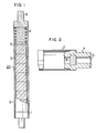
- a fuel element for use in a light water-moderated nuclear reactor or a heavy water-moderated nuclear reactor comprises, as shown in Fig. 1, fuel pellets 3, a thermal insulator 5, a plenum spring 6, etc. filled in a cladding 2, both ends of the cladding 2 being sealed with end plugs 1 and 4 by welding.
- plutonium-enriched fuel has been under way, where plutonium is extracted from a fuel used in a light water-moderated nuclear reactor, and the extracted plutonium is used again in nuclear fuel elements for a light water-moderated nuclear reactor.
- Plutonium-containing nuclear fuel elements can be, of course, used also in a heavy water-moderated nuclear reactor-and also in a fast breeder reactor.
- the first problem is a high hazardness of plutonium and the consequent necessity for zero pollution control of a fabrication plant, different from uranium fuel.
- the second problem is a strong radiation, different from uranium fuel, and the consequent necessity for remote control or automation of a fabrication plant.
- the filter 8 can attain its effect in a degassing and drying step before a true end plug (not shown in the drawing) for sealing is welded to the cladding 2.
- the degassing and drying step is carried out by placing a fuel element with the provisional end plug into a chamber, and heating the fuel element to about 300°C while evacuating the inside of the cladding 2 through a passage 21 in the provisional end plug 7 to remove the moisture from the inside of cladding.
- plutonium particles are also withdrawn from the inside of the nuclear fuel element, but are trapped by the filter 8 in the provisional end plug 7 to prevent its cattering to the outside.
- an inert gas such as a helium gas is filled into the cladding.
- the provisional end plug 7 is removed from the said end of cladding 2, and a plenum spring is inserted into the cladding 2.
- a true end plug for sealing is welded to the cladding, whereby fabrication of nuclear fuel element is completed.
- Nuclear fuel for the heavy water-moderated nuclear reactor has a low plutonium enrichment, for example, about 2%, and thus has a weak radiation.
- the foregoing operations are carried out substantially - manually in a glove box. That is, it is only necessary for the nuclear fuel for the heavy water-moderated nuclear reactor to solve the said first problem.
- plutonium-containing nuclear fuel element for a light water-moderated nuclear reactor has a high plutonium enrichment, for example, about 5%, and even a conventional type nuclear fuel element for the heavy water-moderated nuclear reactor has an increase in nuclear fission products in the nuclear fuel, and thus the intensity of radiation from such nuclear fuels is considerably higher than that of the nuclear fuel elements now available for the heavy water-moderated nuclear reactor.
- the second problem that is, remote control or automation, is necessary for plants handling such nuclear fuels.
- substantially all operations are carried out manually in the plants so far utilized for fabricating nuclear fuels for heavy water-moderated nuclear reactors, and thus the second problem has not been solved yet.
- a provisional end plug as a means for solving the first problem is a large obstacle to the automation, because these plutonium-enriched fuel and nuclear fuel for a heavy water-moderated nuclear reactor have a tendency to make an inside pressure of fuel element higher.
- the inside pressure of fuel element is, of couse, such a high pressure as 30 atmospheres.
- Use of a device for handling the provisional end plug in such a high pressure chamber brings about inconveniences such as a failure in pressure guarantee, a leakage of nuclear fissionable materials through sealed parts, an increase in evacuating time due to an increase in chamber capacity, difficult maintenance of the device from the outside of high pressure chamber, etc.
- a nuclear fuel element having end plugs that can serve to prevent nuclear pollution during the fabrication and can require no handling at all in a vacuum-degassing and drying oven and a pressure chamber is in demand.
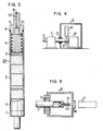
- a nuclear fuel element 24 according to this embodiment is shown, where a low end plug 2 is welded to one end, i.e. the lower end of a cladding 21, and an upper end plug 9 is welded to the other end.
- fuel pellets 3 In the cladding 2, fuel pellets 3, a thermal insulator 5 and a plenum spring 6 are filled.
- the fuel pellets 3 contain uranium and plutonium.
- a filter 10 is provided in the upper end plug 9 and at a position in contact with the atmosphere in the cladding 2.
- a narrow, long recess 22 communicating with the space in the cladding 2 through the filter 10 is provided in the upper end plug 9.
- the narrow, long recess 22 is made by sealing . passage communicating with the outside at point B by welding. Welding position of the upper end plug 9 and the cladding 2 is at A.
- a lower end plug 1 is T IG welded to one end of a cladding 2 under an inert gas atmosphere such as a helium atmosphere under the normal pressure. This procedure is the same for the conventional type nuclear fuel element for a light water-moderated nuclear reactor and a heavy water-moderated nuclear reactor.
- plutonium-containing fuel pellets 3, a thermal insulator 5 and a plenum spring 6 are filled into the cladding 2 in a shielded box called "glove box" to prevent nuclear pollution.
- an upper end plug 9 having a filter 10 at the inside is welded to the cladding 2 in a chamber 13 in a helium gas atmosphere under the normal pressure, shown in Fig. 4.
- the cladding 2 is supported by a gripper 11 and the upper end plug 9 by a gripper 12.
- Numeral 14 is a welder and numeral 15 is a sealing member.
- the chamber inside is evacuated, and nuclear fissionable materials from the inside of the cladding 2 are trapped by the filter 10 in the upper end plug 9 to prevent nuclear pollution of the evaculating system.
- the filter 10 is made from a porous metal or ceramic and can trap nuclear fuel particles having a particle size down to about 0.3 pm.
- the nuclear fuel element is vacuum-degassed and dried. That is, the nuclear fuel element is placed in a drying oven with an evacuating device. By driving the evacuating device, the inside of the drying oven is brought into a vacuum state, whereby the moisture is removed from the nuclear fuel element.
- the filter 10 in the upper end plug_ 9 serves to prevent nuclear pollution at the vacuum-degassing and drying like the evacuation at the welding. After the desired vacuumness has been reached, the drying oven is heated, and thus the moisture is further removed from the cladding 2.
- the nuclear fuel element is subjected to sealing of the passage 23 in the upper end plug 9 in the manner shown in Fig. 5. That is, the head part of the nuclear fuel element is inserted into a welding chamber 13. Sealing of the chamber 13 from the outside is made by the sealing member 15. Then, the inside of the chamber 13 is evacuated, and then a pressurized helium is supplied into the chamber.
- the pressure of helium depends upon the kind of nuclear fuel, but is in a range of a few atmospheres to about 30 atmospheres. The helium supplied into the chamber 13 flows into the cladding 2 through the passage 23.
- a laser beam from a laser welder 17 provided outside the chamber 13 is focused on the tip end of the passage 23 in the upper end plug 9 through a lens 16 to melt the tip end and seal the passage 23, whereby a narrow, long recess 22 shown in Fig. 3 is formed in the upper end plug 9.
- the chamber 13 and the degassing and drying oven are connected to each other and are in a helium atmosphere under the normal pressure, where the provisional end plug 7 is manually removed from the cladding 2, and the plenum spring 6 is inserted into the cladding 2 and then the upper end plug 4 is inserted into the cladding 2. Then, the second end plug 4 is supported by an end plug gripper 12, and an arc gap is controlled by adjusting a TIG welding torch 14. After this operation, peripheral butt welding of the upper end plug 4 and the cladding 2 is carried out to complete the process.
Landscapes
- Engineering & Computer Science (AREA)
- Physics & Mathematics (AREA)
- Plasma & Fusion (AREA)
- General Engineering & Computer Science (AREA)
- High Energy & Nuclear Physics (AREA)
- Manufacturing & Machinery (AREA)
- Butt Welding And Welding Of Specific Article (AREA)
- Catalysts (AREA)
Applications Claiming Priority (2)
| Application Number | Priority Date | Filing Date | Title |
|---|---|---|---|
| JP57183458A JPS5972085A (ja) | 1982-10-18 | 1982-10-18 | 核燃料要素の製造方法 |
| JP183458/82 | 1982-10-18 |
Publications (2)
| Publication Number | Publication Date |
|---|---|
| EP0106347A1 true EP0106347A1 (de) | 1984-04-25 |
| EP0106347B1 EP0106347B1 (de) | 1987-02-25 |
Family
ID=16136127
Family Applications (1)
| Application Number | Title | Priority Date | Filing Date |
|---|---|---|---|
| EP83110339A Expired EP0106347B1 (de) | 1982-10-18 | 1983-10-17 | Verfahren zum Herstellen eines Kernbrennstoffelements |
Country Status (5)
| Country | Link |
|---|---|
| US (1) | US4612159A (de) |
| EP (1) | EP0106347B1 (de) |
| JP (1) | JPS5972085A (de) |
| CA (1) | CA1204229A (de) |
| DE (1) | DE3369893D1 (de) |
Cited By (1)
| Publication number | Priority date | Publication date | Assignee | Title |
|---|---|---|---|---|
| CN103157892A (zh) * | 2011-12-14 | 2013-06-19 | 中核建中核燃料元件有限公司 | 一种燃料元件棒压塞焊接一体化方法 |
Families Citing this family (8)
| Publication number | Priority date | Publication date | Assignee | Title |
|---|---|---|---|---|
| KR100756391B1 (ko) * | 2006-03-15 | 2007-09-10 | 한국원자력연구원 | 내부 피복관 및 외부 피복관의 열유속 조절이 가능한 환형핵연료봉 |
| RU2393560C2 (ru) * | 2008-08-07 | 2010-06-27 | Открытое акционерное общество "Новосибирский завод химконцентратов" | Заглушка тепловыделяющего элемента ядерного реактора |
| US8666018B2 (en) | 2011-01-06 | 2014-03-04 | Westinghouse Electric Company Llc | Nuclear fuel rod plenum spring assembly |
| KR101350822B1 (ko) * | 2013-02-14 | 2014-01-14 | 한국과학기술원 | 고속로용 핵연료봉 |
| US10734121B2 (en) * | 2014-03-12 | 2020-08-04 | Westinghouse Electric Company Llc | Double-sealed fuel rod end plug for ceramic-containing cladding |
| JP6314254B2 (ja) * | 2015-08-25 | 2018-04-18 | 株式会社日立製作所 | 軽水炉用燃料棒及び燃料集合体 |
| US12154698B2 (en) * | 2020-08-05 | 2024-11-26 | Uchicago Argonne, Llc | Coated fuel pellets, methods of making and using same |
| CN117464135B (zh) * | 2023-11-07 | 2026-07-10 | 中核建中核燃料元件有限公司 | 一种新型锆合金燃料棒焊接方法 |
Citations (7)
| Publication number | Priority date | Publication date | Assignee | Title |
|---|---|---|---|---|
| FR1400493A (fr) * | 1964-04-14 | 1965-05-28 | Commissariat Energie Atomique | Procédé pour évacuer l'air enfermé dans une cartouche gainée de combustible nucléaire au cours de sa réalisation |
| FR2034802A1 (de) * | 1969-03-11 | 1970-12-18 | Belgonucleaire Sa | |
| FR2117912A1 (de) * | 1970-12-08 | 1972-07-28 | Westinghouse Electric Corp | |
| GB1362761A (en) * | 1971-05-04 | 1974-08-07 | Belgonucleaire Sa | Nuclear fuel rods |
| FR2233681A1 (de) * | 1973-06-13 | 1975-01-10 | Getters Spa | |
| FR2291578A1 (fr) * | 1974-11-15 | 1976-06-11 | Commissariat Energie Atomique | Element de combustible, pour reacteur nucleaire, et son procede de fabrication |
| US4120752A (en) * | 1976-08-04 | 1978-10-17 | Electric Power Research Institute, Inc. | Mixed oxide fuel pellet for fuel rod of nuclear reactor core |
Family Cites Families (2)
| Publication number | Priority date | Publication date | Assignee | Title |
|---|---|---|---|---|
| US3892626A (en) * | 1970-12-12 | 1975-07-01 | Hitachi Ltd | Vented nuclear fuel element |
| US4010069A (en) * | 1972-01-26 | 1977-03-01 | Siemens Aktiengesellschaft | Nuclear reactor fuel rod |
-
1982
- 1982-10-18 JP JP57183458A patent/JPS5972085A/ja active Granted
-
1983
- 1983-10-17 DE DE8383110339T patent/DE3369893D1/de not_active Expired
- 1983-10-17 EP EP83110339A patent/EP0106347B1/de not_active Expired
- 1983-10-18 CA CA000439177A patent/CA1204229A/en not_active Expired
- 1983-10-18 US US06/542,992 patent/US4612159A/en not_active Expired - Fee Related
Patent Citations (7)
| Publication number | Priority date | Publication date | Assignee | Title |
|---|---|---|---|---|
| FR1400493A (fr) * | 1964-04-14 | 1965-05-28 | Commissariat Energie Atomique | Procédé pour évacuer l'air enfermé dans une cartouche gainée de combustible nucléaire au cours de sa réalisation |
| FR2034802A1 (de) * | 1969-03-11 | 1970-12-18 | Belgonucleaire Sa | |
| FR2117912A1 (de) * | 1970-12-08 | 1972-07-28 | Westinghouse Electric Corp | |
| GB1362761A (en) * | 1971-05-04 | 1974-08-07 | Belgonucleaire Sa | Nuclear fuel rods |
| FR2233681A1 (de) * | 1973-06-13 | 1975-01-10 | Getters Spa | |
| FR2291578A1 (fr) * | 1974-11-15 | 1976-06-11 | Commissariat Energie Atomique | Element de combustible, pour reacteur nucleaire, et son procede de fabrication |
| US4120752A (en) * | 1976-08-04 | 1978-10-17 | Electric Power Research Institute, Inc. | Mixed oxide fuel pellet for fuel rod of nuclear reactor core |
Cited By (1)
| Publication number | Priority date | Publication date | Assignee | Title |
|---|---|---|---|---|
| CN103157892A (zh) * | 2011-12-14 | 2013-06-19 | 中核建中核燃料元件有限公司 | 一种燃料元件棒压塞焊接一体化方法 |
Also Published As
| Publication number | Publication date |
|---|---|
| EP0106347B1 (de) | 1987-02-25 |
| CA1204229A (en) | 1986-05-06 |
| DE3369893D1 (en) | 1987-04-02 |
| JPS5972085A (ja) | 1984-04-23 |
| JPS6319036B2 (de) | 1988-04-21 |
| US4612159A (en) | 1986-09-16 |
Similar Documents
| Publication | Publication Date | Title |
|---|---|---|
| US2992174A (en) | Breeder-converter reactor | |
| US3135665A (en) | Fuel element for a neutronic reactor | |
| US4612159A (en) | Nuclear fuel element and process for fabricating the same | |
| US3459636A (en) | Vented fuel pin | |
| US3322644A (en) | Core element for a breeder nuclear reactor | |
| US7509731B2 (en) | Method and device for manufacturing non-contaminated MOX fuel rods | |
| JPS63212896A (ja) | 細長い部材の解放可能な係合装置 | |
| EP0158100A1 (de) | Giftstab zur Benutzung in einem Kernreaktor | |
| GB1148154A (en) | Refuelling apparatus for a nuclear reactor | |
| US4980091A (en) | Method and device enabling molten radioactive glass to be cast into a container | |
| GB1056732A (en) | Fuel element for a nuclear reactor | |
| US3336201A (en) | Dual fuel cycle for nuclear reactors | |
| JPS60188880A (ja) | 原子炉用燃料集合体 | |
| US4312707A (en) | Nuclear fuel rod | |
| RU2122750C1 (ru) | Способ эксплуатации ядерного энергетического комплекса | |
| JPS6010593B2 (ja) | 核燃料要素 | |
| EP0151920B1 (de) | Verfahren zur Verarbeitung eines Steuerelementes zum Eintauchen in Kernreaktorkühlmittel | |
| GB2115212A (en) | Nuclear fuel element | |
| Sullivan et al. | AECL's progress in DUPIC fuel development | |
| US3379614A (en) | Nuclear reactor fuel channel assembly | |
| JPS5554293A (en) | Assembling method of nuclear fuel rod | |
| US4762673A (en) | Burnable poison rod for use in a nuclear reactor | |
| GB1168054A (en) | Nuclear Fuel Elements | |
| JPS5952998B2 (ja) | 燃料棒 | |
| Goswami et al. | Encapsulation of plutonium based fuel pins |
Legal Events
| Date | Code | Title | Description |
|---|---|---|---|
| PUAI | Public reference made under article 153(3) epc to a published international application that has entered the european phase |
Free format text: ORIGINAL CODE: 0009012 |
|
| AK | Designated contracting states |
Designated state(s): DE FR GB IT SE |
|
| 17P | Request for examination filed |
Effective date: 19840426 |
|
| GRAA | (expected) grant |
Free format text: ORIGINAL CODE: 0009210 |
|
| AK | Designated contracting states |
Kind code of ref document: B1 Designated state(s): DE FR GB IT SE |
|
| REF | Corresponds to: |
Ref document number: 3369893 Country of ref document: DE Date of ref document: 19870402 |
|
| ET | Fr: translation filed | ||
| ITF | It: translation for a ep patent filed | ||
| PLBE | No opposition filed within time limit |
Free format text: ORIGINAL CODE: 0009261 |
|
| STAA | Information on the status of an ep patent application or granted ep patent |
Free format text: STATUS: NO OPPOSITION FILED WITHIN TIME LIMIT |
|
| 26N | No opposition filed | ||
| PGFP | Annual fee paid to national office [announced via postgrant information from national office to epo] |
Ref country code: GB Payment date: 19910808 Year of fee payment: 9 |
|
| ITTA | It: last paid annual fee | ||
| PGFP | Annual fee paid to national office [announced via postgrant information from national office to epo] |
Ref country code: DE Payment date: 19911217 Year of fee payment: 9 |
|
| PGFP | Annual fee paid to national office [announced via postgrant information from national office to epo] |
Ref country code: FR Payment date: 19920814 Year of fee payment: 10 |
|
| PGFP | Annual fee paid to national office [announced via postgrant information from national office to epo] |
Ref country code: SE Payment date: 19920902 Year of fee payment: 10 |
|
| PG25 | Lapsed in a contracting state [announced via postgrant information from national office to epo] |
Ref country code: GB Effective date: 19921017 |
|
| GBPC | Gb: european patent ceased through non-payment of renewal fee |
Effective date: 19921017 |
|
| PG25 | Lapsed in a contracting state [announced via postgrant information from national office to epo] |
Ref country code: DE Effective date: 19930701 |
|
| PG25 | Lapsed in a contracting state [announced via postgrant information from national office to epo] |
Ref country code: SE Effective date: 19931018 |
|
| PG25 | Lapsed in a contracting state [announced via postgrant information from national office to epo] |
Ref country code: FR Effective date: 19940630 |
|
| REG | Reference to a national code |
Ref country code: FR Ref legal event code: ST |
|
| EUG | Se: european patent has lapsed |
Ref document number: 83110339.5 Effective date: 19940510 |