EP0106428A1 - Bahnschlitz- und Falzverfahren - Google Patents
Bahnschlitz- und Falzverfahren Download PDFInfo
- Publication number
- EP0106428A1 EP0106428A1 EP83303001A EP83303001A EP0106428A1 EP 0106428 A1 EP0106428 A1 EP 0106428A1 EP 83303001 A EP83303001 A EP 83303001A EP 83303001 A EP83303001 A EP 83303001A EP 0106428 A1 EP0106428 A1 EP 0106428A1
- Authority
- EP
- European Patent Office
- Prior art keywords
- web
- trim
- parent
- parent web
- segments
- Prior art date
- Legal status (The legal status is an assumption and is not a legal conclusion. Google has not performed a legal analysis and makes no representation as to the accuracy of the status listed.)
- Granted
Links
Images


Classifications
-
- B—PERFORMING OPERATIONS; TRANSPORTING
- B26—HAND CUTTING TOOLS; CUTTING; SEVERING
- B26D—CUTTING; DETAILS COMMON TO MACHINES FOR PERFORATING, PUNCHING, CUTTING-OUT, STAMPING-OUT OR SEVERING
- B26D7/00—Details of apparatus for cutting, cutting-out, stamping-out, punching, perforating, or severing by means other than cutting
- B26D7/18—Means for removing cut-out material or waste
- B26D7/1845—Means for removing cut-out material or waste by non mechanical means
- B26D7/1854—Means for removing cut-out material or waste by non mechanical means by air under pressure
-
- B—PERFORMING OPERATIONS; TRANSPORTING
- B65—CONVEYING; PACKING; STORING; HANDLING THIN OR FILAMENTARY MATERIAL
- B65H—HANDLING THIN OR FILAMENTARY MATERIAL, e.g. SHEETS, WEBS, CABLES
- B65H20/00—Advancing webs
- B65H20/14—Advancing webs by direct action on web of moving fluid
-
- B—PERFORMING OPERATIONS; TRANSPORTING
- B26—HAND CUTTING TOOLS; CUTTING; SEVERING
- B26D—CUTTING; DETAILS COMMON TO MACHINES FOR PERFORATING, PUNCHING, CUTTING-OUT, STAMPING-OUT OR SEVERING
- B26D7/00—Details of apparatus for cutting, cutting-out, stamping-out, punching, perforating, or severing by means other than cutting
- B26D2007/0012—Details, accessories or auxiliary or special operations not otherwise provided for
- B26D2007/0068—Trimming and removing web edges
-
- Y—GENERAL TAGGING OF NEW TECHNOLOGICAL DEVELOPMENTS; GENERAL TAGGING OF CROSS-SECTIONAL TECHNOLOGIES SPANNING OVER SEVERAL SECTIONS OF THE IPC; TECHNICAL SUBJECTS COVERED BY FORMER USPC CROSS-REFERENCE ART COLLECTIONS [XRACs] AND DIGESTS
- Y10—TECHNICAL SUBJECTS COVERED BY FORMER USPC
- Y10T—TECHNICAL SUBJECTS COVERED BY FORMER US CLASSIFICATION
- Y10T83/00—Cutting
- Y10T83/202—With product handling means
- Y10T83/2066—By fluid current
-
- Y—GENERAL TAGGING OF NEW TECHNOLOGICAL DEVELOPMENTS; GENERAL TAGGING OF CROSS-SECTIONAL TECHNOLOGIES SPANNING OVER SEVERAL SECTIONS OF THE IPC; TECHNICAL SUBJECTS COVERED BY FORMER USPC CROSS-REFERENCE ART COLLECTIONS [XRACs] AND DIGESTS
- Y10—TECHNICAL SUBJECTS COVERED BY FORMER USPC
- Y10T—TECHNICAL SUBJECTS COVERED BY FORMER US CLASSIFICATION
- Y10T83/00—Cutting
- Y10T83/202—With product handling means
- Y10T83/2092—Means to move, guide, or permit free fall or flight of product
- Y10T83/2196—Roller[s]
-
- Y—GENERAL TAGGING OF NEW TECHNOLOGICAL DEVELOPMENTS; GENERAL TAGGING OF CROSS-SECTIONAL TECHNOLOGIES SPANNING OVER SEVERAL SECTIONS OF THE IPC; TECHNICAL SUBJECTS COVERED BY FORMER USPC CROSS-REFERENCE ART COLLECTIONS [XRACs] AND DIGESTS
- Y10—TECHNICAL SUBJECTS COVERED BY FORMER USPC
- Y10T—TECHNICAL SUBJECTS COVERED BY FORMER US CLASSIFICATION
- Y10T83/00—Cutting
- Y10T83/647—With means to convey work relative to tool station
- Y10T83/6476—Including means to move work from one tool station to another
- Y10T83/6489—Slitter station
Definitions
- This invention relates to an apparatus and method for manufacturing a grooved automatically dismountable roll paper product.
- U.S. Patent No. 3,038,598 relates to an automatically dismountable roll of strip material which has a bearing wall adapted to be supported upon an appropriate supporting member in a dispenser cabinet and to be automatically dismounted therefrom when it has been consumed to a predetermined extent.
- U.S. Patent 3,089,659 discloses the method of automatically dismounting the roll product of U.S. 3,038,598.
- the bearing wall is formed by the convolutions of the roll product which are relatively disposed to form a recess or detent in the end of the roll.
- U.S. Patent No. 3,282,525 illustrates an apparatus and method which have been utilized to form the recess and bearing surface.
- apparatus for making a spirally wound paper roll product having a bearing wall formed by the convolutions of the roll product comprising a framework provided with a web cutting means and means for feeding a web through the cutting assembly to be.
- the web cutting means comprises a first paper web cutting assembly mounted on the framework, and comprising rotatable means having a plurality of spaced grooves formed about the periphery thereof, anvil knives positioned adjacent to said grooves, and a plurality of circular knife blades positioned within said grooves to define, with said anvil knives, spaced shear slitters for slitting a parent web passing therebetween into separate web segments; a second paper web cutting assembly mounted on said framework positioned downstream from said first assembly and comprising rotatable means having a plurality of spaced grooves formed about the periphery thereof, anvil knives positioned adjacent to said grooves, and a plurality of circular knife blades positioned within said grooves to define with said anvil knives
- a spirally wound paper roll product having a bearing wall formed by the convolutions of the roll product is produced on the apparatus to carry out the slitting of the parent web from which the roll product is formed by the shear slitter cutting arrangement.
- the shear slitter arrangement slits the parent web into separate web segments each of which has a trim segment removed therefrom to create a bearing wall upon winding of the web segment into the finished roll product.
- the later illustrated system also incorporates an improved trim segment removal means which cooperates with the trim segment and the remainder of the web from which it is being cut to facilitate removal of the trim segment and direct same to a predetermined location spaced from the remainder of the web. Further, the trim segment removal means exerts fluid forces at the locations of the shear knives employed in the apparatus to remove any slivers of web that may have adhered thereto.
- Another aspect of the invention provides a method of making a spirally wound paper roll product having a bearing wall formed by the convolutions of the roll product, wherein a parent web is transported along a predetermined path of movement and is slit during such movement, characterized in that at a first location along said path of movement, a first shear slitting operation is performed on said parent web to form lines of cut therein and divide said parent web into separate web segments; at a second location downstream from said first location, a second shear slitting operation is performed on said parent web segments along lines of cut; at least one of said shear cutting operations being periodically moved transversely relative to said parent web so that portions of at least some lines of cut are offset and out of registry periodically so that trim segments are formed; a fluid flow is induced closely adjacent to second location; and said trim segments are removed from the remainder of said parent web at said second location by entraining said trim segments in the fluid flow.
- Roll product 12 includes a core 14 about which layers of paper web have been wound in conventional fashion. It will be seen that a groove 16 is formed at one end thereof. In the particular form shown in the drawings such groove is generally V-shaped in cross section, however, the angle defined by the sidewalls of the groove can be increased or decreased, the depth of the groove can be changed, as can the shape thereof. As will be seen below, the groove is formed by relatively movable shear slitter assemblies and the characteristics of the groove are changed by modifying such relative movement.
- a bearing wall 18 is formed in the roll by the convolutions of the roll product in the vicinity of the groove.
- Bearing wall 18 is adapted to provide a support surface for the roll when it is mounted in a dispensing cabinet of the type shown, for example, in. the aforesaid U.S. Patent No. 3,089,659.
- a dispensing cabinet of the type shown, for example, in. the aforesaid U.S. Patent No. 3,089,659.
- the roll product illustrated in Fig. 3 is prior art and does not form a portion of the present invention, which rather is directed to a specific apparatus and method for producing such roll product.
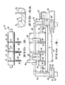
- Fig. 2 illustrates schematically the method of the present invention as applied to a parent web W moving from left to right as viewed in that figure.
- the parent web W first passes through a first paper web cutting assembly 20 which will be described in greater detail below.
- Assembly 20 is reciprocally movable transversely relative to the direction of movement of the parent web W to form lines of cut including offset portions 22.
- the web then continues past a second paper web cutting assembly 26.
- Second paper web cutting assembly 26 forms slits 28 in the web parallel to each other and to an edge 30 of the web. It will be appreciated that trim segments 32 will be formed in the parent web where slits 28 do not register with the lines of cut formed in the parent web by first paper web cutting assembly 20, i.e.
- trim strip 40 will be formed solely by the reciprocating action of first paper web cutting assembly 20. Trim strip 40 is defined by the initial edge 42 of the parent paper web W and offset line of cut portion 22 formed adjacent to edge 42. As will be seen below, both cutting assemblies 20 and 26 are capable of reciprocal movement. In Fig. 1, assembly 20 was moved and assembly 26 held stationary. If it is desired to form a groove at the edge 30 of the parent-web this relationship would obviously be reversed. Alternatively, grooves could be generated at both parent web edges by moving both cutting assemblies.
- the first paper web cutting assembly 20 of the device is mounted on a framework 50.
- Assembly 20 includes a bottom plate 52 and side plates 54 and 56 welded or otherwise secured thereto.
- Rotatably attached to side plates 54 and 56 are a plurality of rollers 60 positioned within channels formed in framework 50 and providing support for assembly 20.
- assembly 20 is thus capable of reciprocal motion relative to the framework.
- such reciprocal motion is imparted to assembly 20 by means of a cam and follower arrangement. More particularly a grooved cam element 62 is rotatably mounted on framework 50.
- a follower element 66 is disposed in the groove of cam element 62 and is integrally connected to side plate 56 by structural member 70.
- Cam element 62 is connected to any suitable drive mechanism.
- a preferred approach is to connect the cam element to the drive of the rewinder (not shown) through a suitable clutch mechanism which is engaged and disengaged in a programmed sequence to determine the position of the finished groove in each successive roll.
- the size of the groove may be varied as desired by utilizing a suitable transmission between the rewinder drive and cam drive mechanism.
- Rotatably mounted in journals formed in side plates 54, 56 and comprising a portion of assembly 20 is a shaft 74 having a plurality of sleeves 73 disposed thereon defining spaced grooves 76.
- Anvil knives 77 are disposed between the sleeves to define a side wall of each groove as shown in Fig. 5A.
- Selectively positionable within grooves 76 in shear cut relationship with anvil knives 77 are a plurality of circular knife blades 78 which are freely rotatably mounted on a blade mounting assembly .82 also extending between side plates 54 and 56.
- Blade mounting assembly 82 is pivotally mounted relative to the side plates so that the entire blade mounting assembly may be manually or mechanically pivoted with respect thereto to place the knife blades 78 into and out of engagement with anvil knives 77.
- the knife blades are rotatably mounted on L-shaped structural members 84 comprising part of the blade mounting assembly 82.
- the parent web W which is driven by any suitable means (not shown) passes through the shear slitters defined by the circular knife blades 78 and the anvil knives 77. As may perhaps best be seen with reference to Fig. 1, the web W then proceeds around an idler roll 88. In the vicinity of the shear slitter adjacent to the edge 42 of the web is an edge trim removal device 90 for removing trim strip 40 from the parent web and conveying strip 40 to a predetermined location such as trim collector 160. Disposed at the open end of edge trim removal device 90 are two Coanda nozzles 92 which when activated induce a fluid flow within the interior of device 90 in the direction illustrated by the dashed arrow in Fig. 1.
- Coanda nozzles 92 may be of any suitable construction but are preferably of the two dimensional type. Any suitable construction may be employed because trim strip 40 is in the form of a continuous ribbon albeit one that varies in width.
- the nozzles are selectively connected to a suitable source of compressed air (not shown).
- the assembly 26 After passing around idler roll 88 the web progresses to second paper web cutting assembly 26.
- the assembly 26 includes a shaft 98 having sleeves 99 about the periphery thereof to define grooves 100 and a plurality of anvil knives 101 positioned between the sleeves. Circular knife blades 102 are positionable within the grooves to define spaced shear slitters with the anvil knives for again slitting the parent web.
- Assembly 26 preferably is mounted on rollers and is selectively reciprocally mounted to move relative to the crosswise direction of web W.
- Shaft 98 is journaled at its ends in suitable bearings in side walls 104 and 106 roller mounted with respect to franework 50.
- freely rotatable knife blades 102 are connected to L-shaped members depending from a cross bar 108 pivotally connected to side walls 104 and 106 so that the blades may be manually or mechanically selectively placed into and out of engagement with the anvil knives 101.
- Trim segment removal means 120 is positioned closely adjacent to second assembly 26 to exert forces on trim segments 32 produced at such location and on the remainder of the parent web to remove the trim segments and direct them to a predetermined location spaced from the remainder of the parent web.
- the details of the trim segment removal means may perhaps best be seen with reference to Figs. 6, 7 and 8.
- a trim segment removal means 120 is positioned in registry with and closely adjacent to each groove 100 and the circular knife blade 102 positionable within the groove.
- the trim segment removal means 120 are preferably mounted on the cross bar 108 along with blades 1.02 so that they can be swung out of the way when the blades are moved out of engagement with the anvil knives.
- Each trim segment removal means 120 includes an open ended conduit 122 defined by conduit side walls 124 and 126 and interconnecting conduit walls 128 and 130 which flare out in Venturi fashion.
- Coanda nozzles 132 and 134 which are selectively connected through hoses 136 and 138 to a suitable source of air pressure (not shown).
- Coanda nozzles As is conventional with Coanda nozzles, when the interiors of nozzles 132 and 134 are filled with pressurized gas such gas will be emitted from exit slits 140 and 142 extending between the conduit side walls and be attached to generally curved Coanda surfaces 144 and 146 which direct fluid flow into the interior of the conduit. This flow of pressurized gas will entrain ambient air therewith so that the combined fluid flow within the conduit interior is comprised not only of the pressurized gas being emitted from the Coanda nozzles but also the ambient air entrained thereby.
- Coanda nozzle 132 also serves to exert a force perpendicular or normal to the web path. Such pulling force is applied not only to trim segment 32 but also to the remainder of the parent web in the immediate vicinity of the trim segment.
- tapered knob numbers 150 and 152 Attached to conduit side walls 124 and 126 are tapered knob numbers 150 and 152 which press against the parent web W at spaced locations adjacent opposite sides of trim segment 32, said spaced locations being disposed a predetermined distance from the trim segment and cooperating with the web pulling Coanda nozzle 132 to manipulate the web to facilitate separation between the trim segment and the remainder of the web.
- the normal force exerted by the fluid flow within the conduit and the generally oppositely directed forces of the tapered knobs pressing against the web will cause the web to be drawn away at the lines of cut forming the trim segment and cause separation at said lines of cut.
- trim segment will then be drawn by the fluid flow within the conduit away from the web W after separation between the trim segment and the remainder of the parent web has been facilitated.
- This action is particularly important at the leading and trailing ends of the trim segment which are extremely fine in character. With the present arrangement even these hairlike portions of the trim segment can be virtually removed in toto and will not interfere with operation of the equipment at high speeds nor adversely influence product quality. If desired, to conserve energy the flow of pressurized air to the nozzles may be interrupted when no trim segment is being cut.
- knobs 150 and 152 be extremely smooth. Chrome plated brass has been found to be one suitable material for this purpose. Insofar as the dimensions and pressures of the Coanda nozzles 132 and 134 are concerned, apparatus constructed in accordance with the teachings of the present invention has been employed utilizing an air slit of 0.002 inches (0.051 mm) and such nozzle has been operated in the general pressure range of 10-12 psig (0.69 to 0.83 bar).
- Coanda nozzle 134 is positioned closely adjacent to knife blade 102. In addition to inducing fluid flow within conduit 122, Coanda nozzle 134 performs the additional function of exerting strong fluid flow at the cutting edge of the knife blade. This action removes any slivers which may attach to or wrap about the slitter blade during operation of the present invention. All of the waste material delivered by conduit 122 will be delivered to a suitable location such as trim collector 160.
- the character of the groove 16 of the finished product may be readily varied by changing the configuration and/or rotational speed of the cam element 62.
Landscapes
- Life Sciences & Earth Sciences (AREA)
- Forests & Forestry (AREA)
- Engineering & Computer Science (AREA)
- Mechanical Engineering (AREA)
- Nonmetal Cutting Devices (AREA)
- Replacement Of Web Rolls (AREA)
- Winding Of Webs (AREA)
- Perforating, Stamping-Out Or Severing By Means Other Than Cutting (AREA)
Priority Applications (1)
| Application Number | Priority Date | Filing Date | Title |
|---|---|---|---|
| AT83303001T ATE18887T1 (de) | 1982-09-23 | 1983-05-24 | Bahnschlitz- und falzverfahren. |
Applications Claiming Priority (2)
| Application Number | Priority Date | Filing Date | Title |
|---|---|---|---|
| US06/422,319 US4484500A (en) | 1982-09-23 | 1982-09-23 | Web slitting and grooving system |
| US422319 | 1989-10-16 |
Publications (2)
| Publication Number | Publication Date |
|---|---|
| EP0106428A1 true EP0106428A1 (de) | 1984-04-25 |
| EP0106428B1 EP0106428B1 (de) | 1986-04-02 |
Family
ID=23674349
Family Applications (1)
| Application Number | Title | Priority Date | Filing Date |
|---|---|---|---|
| EP83303001A Expired EP0106428B1 (de) | 1982-09-23 | 1983-05-24 | Bahnschlitz- und Falzverfahren |
Country Status (5)
| Country | Link |
|---|---|
| US (1) | US4484500A (de) |
| EP (1) | EP0106428B1 (de) |
| AT (1) | ATE18887T1 (de) |
| CA (1) | CA1199570A (de) |
| DE (1) | DE3362767D1 (de) |
Cited By (3)
| Publication number | Priority date | Publication date | Assignee | Title |
|---|---|---|---|---|
| WO2009022053A1 (en) * | 2007-08-10 | 2009-02-19 | Metso Paper, Inc. | Trim strip slitting and removal arrangement and method of trim strip slitting and removal |
| CN108629906A (zh) * | 2017-03-17 | 2018-10-09 | 深圳市祈飞科技有限公司 | 吸管取用装置 |
| WO2023280706A1 (de) * | 2021-07-07 | 2023-01-12 | Focke & Co. (Gmbh & Co. Kg) | Verfahren und vorrichtung zur handhabung von abschnitten einer materialbahn |
Families Citing this family (17)
| Publication number | Priority date | Publication date | Assignee | Title |
|---|---|---|---|---|
| US4542842A (en) * | 1983-10-31 | 1985-09-24 | Crown Zellerbach Corporation | Pneumatic conveying method for flexible webs |
| DE3416341A1 (de) * | 1984-05-03 | 1985-11-14 | Jagenberg AG, 4000 Düsseldorf | Verfahren und vorrichtung zum abfuehren von randstreifen von materialbahnen aus papier, karton oder dergleichen |
| US4951891A (en) * | 1989-01-23 | 1990-08-28 | James River Corporation | Web slitter and groover system |
| US5533659A (en) * | 1991-09-14 | 1996-07-09 | Beloit Technologies, Inc. | Dust removal system |
| DE9111448U1 (de) * | 1991-09-14 | 1993-01-28 | Beloit Corp., Beloit, Wis. | Breitstreckeinrichtung für Rollenschneidemaschinen |
| US6394330B1 (en) * | 1998-08-13 | 2002-05-28 | 3M Innovative Properties Company | Method for slitting and processing a web into plural use supply forms |
| FI105463B (fi) | 1999-01-22 | 2000-08-31 | Valmet Corp | Menetelmä ja laite paperirainan rullauksessa |
| CA2370242A1 (en) | 2001-03-07 | 2002-09-07 | Dieter H. Hilker | Water jet edge cutter with integral trim chute |
| US20020134208A1 (en) * | 2001-03-23 | 2002-09-26 | Wilson John E. | Method and apparatus for trimming sheet metal |
| FI20011005A7 (fi) | 2001-05-14 | 2002-11-15 | Metso Paper Inc | Menetelmä paperi- tai kartonkikoneen pituusleikkurin asetteen teossa |
| US20050092146A1 (en) * | 2003-10-29 | 2005-05-05 | Kimberly-Clark Worldwide, Inc. | Method and apparatus for removing material from a moving substrate |
| FI116664B (fi) | 2004-06-18 | 2006-01-31 | Metso Paper Inc | Menetelmä ja laite paperi- tai kartonkikoneessa |
| FI122538B (fi) | 2009-11-24 | 2012-03-15 | Metso Paper Inc | Kuiturainan pituusleikkuri ja menetelmä kuiturainan pituusleikkaamiseksi |
| US8794624B2 (en) | 2012-06-21 | 2014-08-05 | Xerox Corporation | Method and apparatus for a pneumatic baffle to selectively direct a cut media in a media feed system |
| DE102014102604A1 (de) | 2014-02-27 | 2015-08-27 | Windmöller & Hölscher Kg | Vorrichtung zum automatischen Schneiden und Abführen einer Materialbahn sowie Verfahren hierzu |
| US10421206B2 (en) | 2014-07-30 | 2019-09-24 | Minigraphics, Inc. | Progressive slitting apparatus |
| JP2023097674A (ja) * | 2021-12-28 | 2023-07-10 | 株式会社東伸 | 切断屑除去装置 |
Citations (4)
| Publication number | Priority date | Publication date | Assignee | Title |
|---|---|---|---|---|
| US3038598A (en) * | 1960-04-01 | 1962-06-12 | Towlsaver Inc | Automatically dismountable roll |
| US3282525A (en) * | 1963-09-23 | 1966-11-01 | Crown Zellerbach Corp | Web slitting and grooving apparatus and method |
| US3536273A (en) * | 1969-02-07 | 1970-10-27 | Du Pont | Method of and apparatus for winding a web of plastic film |
| GB2044658A (en) * | 1979-03-23 | 1980-10-22 | Mitsubishi Heavy Ind Ltd | Trim guide device for slitting/scoring machines |
Family Cites Families (4)
| Publication number | Priority date | Publication date | Assignee | Title |
|---|---|---|---|---|
| DE2020398A1 (de) * | 1970-04-25 | 1971-11-11 | Krupp Gmbh | Streifenabnahmevorrichtung |
| US3741052A (en) * | 1971-04-22 | 1973-06-26 | Oxford Industries | Button line strip cutter and stacker |
| US4242934A (en) * | 1979-02-09 | 1981-01-06 | Molins Machine Company, Inc. | Trim chute apparatus |
| SE430231B (sv) * | 1980-02-05 | 1983-10-31 | Tetra Pak Int | Anordning for reducering av en lopande materialbanas tjocklek |
-
1982
- 1982-09-23 US US06/422,319 patent/US4484500A/en not_active Expired - Lifetime
-
1983
- 1983-05-13 CA CA000428083A patent/CA1199570A/en not_active Expired
- 1983-05-24 AT AT83303001T patent/ATE18887T1/de not_active IP Right Cessation
- 1983-05-24 EP EP83303001A patent/EP0106428B1/de not_active Expired
- 1983-05-24 DE DE8383303001T patent/DE3362767D1/de not_active Expired
Patent Citations (4)
| Publication number | Priority date | Publication date | Assignee | Title |
|---|---|---|---|---|
| US3038598A (en) * | 1960-04-01 | 1962-06-12 | Towlsaver Inc | Automatically dismountable roll |
| US3282525A (en) * | 1963-09-23 | 1966-11-01 | Crown Zellerbach Corp | Web slitting and grooving apparatus and method |
| US3536273A (en) * | 1969-02-07 | 1970-10-27 | Du Pont | Method of and apparatus for winding a web of plastic film |
| GB2044658A (en) * | 1979-03-23 | 1980-10-22 | Mitsubishi Heavy Ind Ltd | Trim guide device for slitting/scoring machines |
Cited By (3)
| Publication number | Priority date | Publication date | Assignee | Title |
|---|---|---|---|---|
| WO2009022053A1 (en) * | 2007-08-10 | 2009-02-19 | Metso Paper, Inc. | Trim strip slitting and removal arrangement and method of trim strip slitting and removal |
| CN108629906A (zh) * | 2017-03-17 | 2018-10-09 | 深圳市祈飞科技有限公司 | 吸管取用装置 |
| WO2023280706A1 (de) * | 2021-07-07 | 2023-01-12 | Focke & Co. (Gmbh & Co. Kg) | Verfahren und vorrichtung zur handhabung von abschnitten einer materialbahn |
Also Published As
| Publication number | Publication date |
|---|---|
| US4484500A (en) | 1984-11-27 |
| ATE18887T1 (de) | 1986-04-15 |
| CA1199570A (en) | 1986-01-21 |
| DE3362767D1 (en) | 1986-05-07 |
| EP0106428B1 (de) | 1986-04-02 |
Similar Documents
| Publication | Publication Date | Title |
|---|---|---|
| EP0106428B1 (de) | Bahnschlitz- und Falzverfahren | |
| US5024128A (en) | Sheeter for web fed printing press | |
| US3008366A (en) | Paper perforating mechanism | |
| US3877353A (en) | Stripping device | |
| GB1581916A (en) | Web winding and cutting apparatus for association with the final stage of a web treatment machine such as a printing machine | |
| US4452114A (en) | Apparatus for continuously cutting and removing thin trim strips from a printed web | |
| US5290226A (en) | Method of and apparatus for cutting a web and folding the resulting ribbons | |
| KR0133352B1 (ko) | 웨브재료의 절단방법 및 장치, 와 리와인더 | |
| US3056323A (en) | Progressive transverse web cutting apparatus | |
| US1006783A (en) | Rotary cutting device. | |
| US4409870A (en) | Apparatus for continuously cutting and removing thin trim strips from a printed web | |
| US4499801A (en) | Web slitting and grooving method | |
| GB2097766A (en) | Web-introduction apparatus on winding machines | |
| US3611855A (en) | Cutting apparatus | |
| US4492138A (en) | Apparatus for delivering web material or the like from rolls | |
| JP3934806B2 (ja) | ウエブ材の加工装置 | |
| US5067698A (en) | Method and apparatus for manufacturing interfolded toweling | |
| US6895845B2 (en) | Rotary sheeter having an improved vacuum means for cross trim removal | |
| US4621956A (en) | Method and apparatus for cutting of flexible foam material | |
| US3147656A (en) | Apparatus for making cutouts from a traveling web | |
| EP3431236B1 (de) | Ausrüstung und verfahren zum transversalen schneiden von trimbändern | |
| US4914995A (en) | Rotary cutting apparatus | |
| EP0842881A2 (de) | Verfahren zur Herstellung einer kernlosen Papierrolle | |
| US6669617B1 (en) | Paper web folding and cutting apparatus | |
| EP0096984A2 (de) | Verfahren zur Herstellung einer Papierrolle |
Legal Events
| Date | Code | Title | Description |
|---|---|---|---|
| PUAI | Public reference made under article 153(3) epc to a published international application that has entered the european phase |
Free format text: ORIGINAL CODE: 0009012 |
|
| AK | Designated contracting states |
Designated state(s): AT BE CH DE FR GB IT LI LU NL SE |
|
| 17P | Request for examination filed |
Effective date: 19840330 |
|
| GRAA | (expected) grant |
Free format text: ORIGINAL CODE: 0009210 |
|
| AK | Designated contracting states |
Kind code of ref document: B1 Designated state(s): AT BE CH DE FR GB IT LI LU NL SE |
|
| PG25 | Lapsed in a contracting state [announced via postgrant information from national office to epo] |
Ref country code: NL Effective date: 19860402 Ref country code: LI Effective date: 19860402 Ref country code: IT Free format text: LAPSE BECAUSE OF FAILURE TO SUBMIT A TRANSLATION OF THE DESCRIPTION OR TO PAY THE FEE WITHIN THE PRESCRIBED TIME-LIMIT;WARNING: LAPSES OF ITALIAN PATENTS WITH EFFECTIVE DATE BEFORE 2007 MAY HAVE OCCURRED AT ANY TIME BEFORE 2007. THE CORRECT EFFECTIVE DATE MAY BE DIFFERENT FROM THE ONE RECORDED. Effective date: 19860402 Ref country code: CH Effective date: 19860402 Ref country code: BE Effective date: 19860402 Ref country code: AT Effective date: 19860402 |
|
| REF | Corresponds to: |
Ref document number: 18887 Country of ref document: AT Date of ref document: 19860415 Kind code of ref document: T |
|
| REF | Corresponds to: |
Ref document number: 3362767 Country of ref document: DE Date of ref document: 19860507 |
|
| PG25 | Lapsed in a contracting state [announced via postgrant information from national office to epo] |
Ref country code: LU Free format text: LAPSE BECAUSE OF NON-PAYMENT OF DUE FEES Effective date: 19860531 |
|
| REG | Reference to a national code |
Ref country code: CH Ref legal event code: PL |
|
| ET | Fr: translation filed | ||
| NLV1 | Nl: lapsed or annulled due to failure to fulfill the requirements of art. 29p and 29m of the patents act | ||
| PLBE | No opposition filed within time limit |
Free format text: ORIGINAL CODE: 0009261 |
|
| STAA | Information on the status of an ep patent application or granted ep patent |
Free format text: STATUS: NO OPPOSITION FILED WITHIN TIME LIMIT |
|
| 26N | No opposition filed | ||
| EAL | Se: european patent in force in sweden |
Ref document number: 83303001.8 |
|
| REG | Reference to a national code |
Ref country code: GB Ref legal event code: IF02 |
|
| PGFP | Annual fee paid to national office [announced via postgrant information from national office to epo] |
Ref country code: GB Payment date: 20020501 Year of fee payment: 20 |
|
| PGFP | Annual fee paid to national office [announced via postgrant information from national office to epo] |
Ref country code: SE Payment date: 20020513 Year of fee payment: 20 |
|
| PGFP | Annual fee paid to national office [announced via postgrant information from national office to epo] |
Ref country code: FR Payment date: 20020529 Year of fee payment: 20 |
|
| PGFP | Annual fee paid to national office [announced via postgrant information from national office to epo] |
Ref country code: DE Payment date: 20020628 Year of fee payment: 20 |
|
| PG25 | Lapsed in a contracting state [announced via postgrant information from national office to epo] |
Ref country code: GB Free format text: LAPSE BECAUSE OF EXPIRATION OF PROTECTION Effective date: 20030523 |
|
| REG | Reference to a national code |
Ref country code: GB Ref legal event code: PE20 |
|
| EUG | Se: european patent has lapsed |