EP0106455A1 - Fühler für Luftdurchflussmengen - Google Patents
Fühler für Luftdurchflussmengen Download PDFInfo
- Publication number
- EP0106455A1 EP0106455A1 EP83304776A EP83304776A EP0106455A1 EP 0106455 A1 EP0106455 A1 EP 0106455A1 EP 83304776 A EP83304776 A EP 83304776A EP 83304776 A EP83304776 A EP 83304776A EP 0106455 A1 EP0106455 A1 EP 0106455A1
- Authority
- EP
- European Patent Office
- Prior art keywords
- sensor
- film
- resistor
- resistor element
- airflow
- Prior art date
- Legal status (The legal status is an assumption and is not a legal conclusion. Google has not performed a legal analysis and makes no representation as to the accuracy of the status listed.)
- Granted
Links
- 229910052751 metal Inorganic materials 0.000 claims abstract description 19
- 239000002184 metal Substances 0.000 claims abstract description 19
- 238000001816 cooling Methods 0.000 claims abstract description 10
- 230000000694 effects Effects 0.000 claims abstract description 8
- 238000011144 upstream manufacturing Methods 0.000 claims abstract description 6
- 230000008859 change Effects 0.000 claims description 5
- 230000001419 dependent effect Effects 0.000 claims description 2
- 230000001747 exhibiting effect Effects 0.000 claims description 2
- 238000010438 heat treatment Methods 0.000 claims description 2
- 238000002955 isolation Methods 0.000 claims description 2
- RYGMFSIKBFXOCR-UHFFFAOYSA-N Copper Chemical compound [Cu] RYGMFSIKBFXOCR-UHFFFAOYSA-N 0.000 abstract description 8
- 238000005259 measurement Methods 0.000 abstract description 4
- 229920001721 polyimide Polymers 0.000 abstract description 3
- 239000011889 copper foil Substances 0.000 abstract description 2
- 239000011888 foil Substances 0.000 abstract 2
- 239000004642 Polyimide Substances 0.000 abstract 1
- 239000003570 air Substances 0.000 description 26
- 229910052802 copper Inorganic materials 0.000 description 6
- 239000010949 copper Substances 0.000 description 6
- 230000004044 response Effects 0.000 description 6
- 239000012080 ambient air Substances 0.000 description 5
- 229920003223 poly(pyromellitimide-1,4-diphenyl ether) Polymers 0.000 description 4
- 238000000576 coating method Methods 0.000 description 3
- NJPPVKZQTLUDBO-UHFFFAOYSA-N novaluron Chemical compound C1=C(Cl)C(OC(F)(F)C(OC(F)(F)F)F)=CC=C1NC(=O)NC(=O)C1=C(F)C=CC=C1F NJPPVKZQTLUDBO-UHFFFAOYSA-N 0.000 description 3
- BASFCYQUMIYNBI-UHFFFAOYSA-N platinum Chemical compound [Pt] BASFCYQUMIYNBI-UHFFFAOYSA-N 0.000 description 3
- 229910000679 solder Inorganic materials 0.000 description 3
- 239000004411 aluminium Substances 0.000 description 2
- 229910052782 aluminium Inorganic materials 0.000 description 2
- XAGFODPZIPBFFR-UHFFFAOYSA-N aluminium Chemical compound [Al] XAGFODPZIPBFFR-UHFFFAOYSA-N 0.000 description 2
- 238000004140 cleaning Methods 0.000 description 2
- 239000011248 coating agent Substances 0.000 description 2
- 239000004020 conductor Substances 0.000 description 2
- 239000000356 contaminant Substances 0.000 description 2
- 238000011109 contamination Methods 0.000 description 2
- 239000003989 dielectric material Substances 0.000 description 2
- 230000037361 pathway Effects 0.000 description 2
- 239000000758 substrate Substances 0.000 description 2
- WYTGDNHDOZPMIW-RCBQFDQVSA-N alstonine Natural products C1=CC2=C3C=CC=CC3=NC2=C2N1C[C@H]1[C@H](C)OC=C(C(=O)OC)[C@H]1C2 WYTGDNHDOZPMIW-RCBQFDQVSA-N 0.000 description 1
- 125000003118 aryl group Chemical group 0.000 description 1
- 238000002485 combustion reaction Methods 0.000 description 1
- 238000010276 construction Methods 0.000 description 1
- 230000008878 coupling Effects 0.000 description 1
- 238000010168 coupling process Methods 0.000 description 1
- 238000005859 coupling reaction Methods 0.000 description 1
- 238000005538 encapsulation Methods 0.000 description 1
- 239000000446 fuel Substances 0.000 description 1
- 230000006698 induction Effects 0.000 description 1
- 238000009413 insulation Methods 0.000 description 1
- 238000004519 manufacturing process Methods 0.000 description 1
- 239000000463 material Substances 0.000 description 1
- 229910000510 noble metal Inorganic materials 0.000 description 1
- 230000003647 oxidation Effects 0.000 description 1
- 238000007254 oxidation reaction Methods 0.000 description 1
- 229910052697 platinum Inorganic materials 0.000 description 1
- 229920000642 polymer Polymers 0.000 description 1
- 239000013641 positive control Substances 0.000 description 1
- 230000001681 protective effect Effects 0.000 description 1
- 230000035945 sensitivity Effects 0.000 description 1
- 230000035939 shock Effects 0.000 description 1
- 238000004804 winding Methods 0.000 description 1
Images

Classifications
-
- G—PHYSICS
- G01—MEASURING; TESTING
- G01F—MEASURING VOLUME, VOLUME FLOW, MASS FLOW OR LIQUID LEVEL; METERING BY VOLUME
- G01F1/00—Measuring the volume flow or mass flow of fluid or fluent solid material wherein the fluid passes through a meter in a continuous flow
- G01F1/68—Measuring the volume flow or mass flow of fluid or fluent solid material wherein the fluid passes through a meter in a continuous flow by using thermal effects
- G01F1/684—Structural arrangements; Mounting of elements, e.g. in relation to fluid flow
- G01F1/6842—Structural arrangements; Mounting of elements, e.g. in relation to fluid flow with means for influencing the fluid flow
-
- G—PHYSICS
- G01—MEASURING; TESTING
- G01F—MEASURING VOLUME, VOLUME FLOW, MASS FLOW OR LIQUID LEVEL; METERING BY VOLUME
- G01F1/00—Measuring the volume flow or mass flow of fluid or fluent solid material wherein the fluid passes through a meter in a continuous flow
- G01F1/68—Measuring the volume flow or mass flow of fluid or fluent solid material wherein the fluid passes through a meter in a continuous flow by using thermal effects
- G01F1/684—Structural arrangements; Mounting of elements, e.g. in relation to fluid flow
- G01F1/688—Structural arrangements; Mounting of elements, e.g. in relation to fluid flow using a particular type of heating, cooling or sensing element
- G01F1/69—Structural arrangements; Mounting of elements, e.g. in relation to fluid flow using a particular type of heating, cooling or sensing element of resistive type
- G01F1/692—Thin-film arrangements
Definitions
- This invention relates to a mass airflow sensor.
- a well-known vortex type of meter utilizes an obstacle in the air stream to generate vortices and a transducer such as a hot wire sensor measures the frequency of the vortices, which is a direct measure of air velocity.
- a transducer such as a hot wire sensor measures the frequency of the vortices, which is a direct measure of air velocity.
- the vortex- type meters are not suited to the wide dynamic range of airflow experienced in automotive engines, in that a meter designed for operation at the high flow rates experienced in an engine is ineffective for measuring the lowest flow rates experienced and vice versa.
- the hot wire meter comprising a resistence bridge which includes a fine wire platinum resistor disposed in one of the arms and forming the air mass flew sensor element.
- the bridge is supplied with power sufficient to maintain the sensor resistor at a given temperature above ambient air temperature, and the bridge voltage or the power dissipated in the resistor are measures of the air mass flow.
- this hot wire analogue meter is sound and provides good results. In practice, however, contamination of the wire surface by dirt build-up greatly changes the cooling effect of the air, so that the system calibration is then erroneous. Thus frequent cleaning of the wire is necessary. Also, experience indicates that the fine sensor wire is subject to breakage incidental to engine backfire.
- Still another proposal using the same analogue hot wire approach achieves a rugged sensor by winding the wire on a core.
- a sensor has a high thermal mass due to the presence of the core, so that the temperature of the resistor element responds slowly to',changes in mass airflow of the air stream and thus falls short of requirements in the automotive vehicle application, where rapid temperature changes and rapid airflow changes are frequently encountered.
- thermal'mass in relation to the film resistor element is used herein to refer to the heat capacity of the sensor resistor itself combined with the heat capacity of the film support structure in intimate heat transfer relation with the sensor resistor, which together effectively retard changes in the sensor resistor temperature upon changes in mass airflow.
- the present invention is concerned with providing a mass airflow sensor which is accurate, rugged, useful over a wide dynamic range of flow rates, has rapid response to flow rate changes and is substantially unaffected by dirt build-up.
- a mass airflow sensor in accordance with the present invention is characterised in that the film resistor element includes a dielectric film and a metal film sensor resistor supported on the dielectric film, the dielectric film having mounting regions spaced from the metal film, and the metal film exhibiting a substantial change of resistivity with _temperature, support means engages the film resistor element at the said mounting regions with the sensor -resisitor spaced from the support means for thermal isolation from the support means, whereby the resistor element has small thermal mass, and means is provided for directing the flow of an airstream towards the film resistor element at an oblique angle to obtain a consistent airflow at the resistor element and a positive cooling effect by the airstream.
- the film resistor element potentially has a low thermal mass, to permit quick response to changes in mass airflow.
- the film resistor element includes a planar resistive film sensor which is exposed on both sides of the film to the air stream, with the air stream being directed at an oblique angle to each side and converging at the film sensor for maximum cooling effect by the air.
- the mass airflow sensor in accordance with the present invention is of the constant-temperature anemometer type referred to above, namely the type in which for any given ambient air temperature the sensor resistor is held at a constant temperature above the ambient temperature even though the flow rate may vary. For example, if the ambient air temperature is 20°C, the sensor resistor may be held at 100°C.
- the sensor resistor is in a Wheatstone bridge arrangement with other resistors including a compensating resistor which is sensitive to the ambient air temperature.
- the bridge is supplied by a power supply which is controlled by a feedback circuit to maintain sufficient voltage across the bridge for the sensor resistor to be at its required temperature irrespective of the varying power dissipation from the resistor caused by changes in the mass airflow.
- the resulting bridge voltage or the power dissipated provides a measure of the mass airflow.
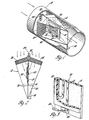
- FIG. 1 A preferred embodiment of a mass airflow sensor in accordance with the present invention is shown in Figures 1, 2 and 3: this sensor has general application to mass airflow measurements, but it has been specifically designed for the measurement of mass airflow inducted into an automotive internal combustion engine, and is thus adapted for operation over a wide dynamic range of airflow, over a wide ambient temperature range, and able to withstand vibration, dirt and engine backfire shocks.
- a cylindrical duct 10 contains a sensor 12 which includes a support frame 14 that is generally planar and has along one edge thereof a flange portion 16 for mounting to a wall of the duct 10.
- the duct 10 and frame 14 have been made of aluminium or a moulded polymer with equally successful results.
- the frame extends longitudinally in the duct and lies on the duct central axis.
- a rectangular aperture 18 in the frame 14 is also symmetrically positioned with respect to the duct axis.
- a planar film resistor element 20 slightly larger than the aperture 18 is .adhesively supported at its margins on the frame 14 over the aperture.
- the body of the element 20 is a dielectric film 21 which is preferably an aromatic polyimide film such as Kapton (trademark of E. I.
- the polyimide film is strong and flexible, and it exhibits low heat transfer laterally and has'high temperature stability.
- the metal film resistor 22 is smaller in area than the dielectric film 21 and is spaced from the edges of the film 21 to define the margins thereof.
- the metal film resistor has a substantial change of resistivity with temperature, and preferably has a linear characteristic. In practice it has been found that the optimum material is copper secured to the dielectric film and etched in a serpentine pathway to achieve the desired resistance, say 5 ohms at a temperature of 95°C.
- the resistance changes linearly with temperature, and has a value of 3.8619 ohms at 20 o C .
- the resistor has a substantial change of resistivity with temperature.
- Each end of the resistive pathway then terminates at a solder pad 24, each pad, in turn, being connected by conductive leads 26 to the airflow circuit.
- a specific example of one such sensor which had an aperture of about 25.4 mm (one inch) square used a 0.0254 mm (one mil) thick Kapton substrate with 7.08g (one quarter ounce) copper foil adhered to one side.
- An area of 19.05 mm by 7.62 mm (0.75 inch by 0.3 inch) etched into a serpentines-shaped circuit developed the required resistance.
- the copper resistance path was 0.00965 mm (0.38 mil) thick and 0.254 mm (10 mils) wide.
- the copper surface was protected by another film 27 of dielectric material such as another sheet of Kapton 0.0254 mm (one mil) thick adhesively secured to the substrate, although other dielectric coatings can be used.
- the resulting encapsulation of the copper resistor prevents oxidation and also presents a smooth surface to the airflow to diminish any tendency to collect dirt on the sensor resistor surface.
- the thermal mass of the sensor resistor element 20 is kept low due to the small mass of the copper-Kapton assembly and its very effective insulation from the support frame 14, while the cooling area encompassing both sides of the planar element 20 is large.
- an aluminium honeycomb flow straightener 28 extends from the frame towards the wall of the duct 10 and is placed at such an angle relative to the frame that air will flow through the flow straighteners 28 in two airflow paths converging towards the film and will impinge upon both sides of the metal film sensor resistor 22.
- the flow straighteners 28 are supported by upper and lower supports 30 which extend along opposite sides of the flow straighteners and along the frame, each support coming to a point at the downstream end of the frame 14, to thereby provide a kite-shaped configuration.
- each flow straightener is at an angle of 70°C to the plane of the frame 14. The optimum angle of the flow straighteners is determined empirically for a given design.
- the angle is not critical and may be varied by say 10° either way from the nominal 70 0 position. If the angle is too large, however, the resolution of the sensor deteriorates, whereas a smaller angle tends to restrict airflow through the duct 10.
- the convergent airflow obtained by the flow straighteners tends to sweep away any insulating layer of air adhering to the sensor surface, to improve thermal coupling of the airflow with the sensor to enhance sensor cooling. Also, this positive control of airflow enhances consistent airflow throughout a range of airflow conditions.
- the upper and lower supports 30 help sustain a consistent airflow by preventing interference with the air passing through the straighteners by that air which has bypassed the flow straighteners along the walls of the duct 10.
- a gap between the flow straighteners at the upstream side thereof is closed by a SEmicylindrical fairing 32 which helps to streamline the flow to the straighteners.
- a temperature-compensating resistor 34 which is a part of a bridge circuit for an air meter, is mounted adjacent the fairing 32 and upstream thereof. The resistor leads extend into the fairing 32 for routing to the electronic circuit. The positioning of the compensating resistor 34 is not critical as long as it is placed in a portion of the ambient air which has not been heated by the sensor resistor 22.
- the mass airflow sensor as just described thus provides a rugged sensing element having a low thermal mass and a large area swept by the impinging air stream which converges on both sides of the sensing element to effect rapid response to changes in mass airflow. Further, due to the large planar area of the sensing element, contamination thereof has little effect on the sensor operation. For example, a 0.0254 mm (one mil) coating of contaminants effects substantially no change in the cooling area of the flat metal film resistor. In contrast, if a prior- art hot wire sensor which uses a round 0.1016 mm (four mil) diameter platinum wire collects a 0.0254 mm (one mil) coating of contaminants, the cooling area of the wire will increase by 50%, thereby causing severe calibration errors and requiring frequent cleaning of the wire.
- the use of copper for the resistance element eliminates any dependence on noble metals, which are very expensive and can at times be difficult to obtain.
- the linearity of the coefficient of the copper with temperature helps to simplify the electronic circuitry of the meter which-produces an electrical signal representing mass airflow.
- the second embodiment of the mass airflow sensor as shown in Figures 4, 5 and 6 comprises a duct 40 having a flow straightener 42 in the upstream end for directing air axially along the duct.
- a diamond-shaped body 44 preferably of dielectric material, is suspended in the duct substantially at the longitudinal axis of the duct, and is mounted on a streamlined pedestal 46 that is attached to the wall of the duct.
- the body 44 is positioned so that a sharp wedge-shaped front portion is poised to cleave the oncoming air stream.
- the front portion of the body 44 contains a cavity 48 intersecting both front faces 49.
- a film resistor element 50 which, as is best seen in Figure 6, includes a pair of metal film resistors 52 connected in series by a low-resistance conductor 54 and terminating at their extreme ends in solder pads 56.
- the film resistor element is wrapped around the front portion of the body 44 so that the resistors 52 are facing inwardly and positioned over the openings in the front faces 49, and the conductor 54 transverses the front apex of the body 44.
- Leads 57 connected to the solder pads 56 are routed internally through hollow parts of the body 44 and pedestal 46 to an electronic circuit, not shown.
- each resistor 52 provides a smooth frontal area to the oncoming air stream, and the large-area resistors 52 readily dissipate their heat to that air stream, thereby providing a rapid response to mass airflow changes.
- the inside of each resistor 52 is exposed to a dead air space in the cavity 48, so that the amount of effective cooling air is about one-half that of the preferred embodiment of Figures 1 to 3 described above. Still, the response of the sensor is good for many applications, and the sensor has the advantages of simple construction and low expense.
- the fabrication of the film resistor element is substantially like that of the preferred embodiment, although the protective film 27 is optional.
- a temperature-compensating resistor 58 is placed at the trailing edge of the support pedestal 46; again, that placement is not critical as long as the resistor 58 is exposed to air not heated by the film resistor element 50. It has been found in practice that an included angle of 20 0 C between the front faces of the body 44 is satisfactory, although larger angles have been tried with equally good results.
Landscapes
- Physics & Mathematics (AREA)
- Fluid Mechanics (AREA)
- General Physics & Mathematics (AREA)
- Measuring Volume Flow (AREA)
Applications Claiming Priority (2)
| Application Number | Priority Date | Filing Date | Title |
|---|---|---|---|
| US06/419,937 US4433576A (en) | 1982-09-20 | 1982-09-20 | Mass airflow sensor |
| US419937 | 1982-09-20 |
Publications (2)
| Publication Number | Publication Date |
|---|---|
| EP0106455A1 true EP0106455A1 (de) | 1984-04-25 |
| EP0106455B1 EP0106455B1 (de) | 1986-05-07 |
Family
ID=23664369
Family Applications (1)
| Application Number | Title | Priority Date | Filing Date |
|---|---|---|---|
| EP83304776A Expired EP0106455B1 (de) | 1982-09-20 | 1983-08-18 | Fühler für Luftdurchflussmengen |
Country Status (5)
| Country | Link |
|---|---|
| US (1) | US4433576A (de) |
| EP (1) | EP0106455B1 (de) |
| JP (1) | JPS5975120A (de) |
| CA (1) | CA1197706A (de) |
| DE (1) | DE3363402D1 (de) |
Cited By (4)
| Publication number | Priority date | Publication date | Assignee | Title |
|---|---|---|---|---|
| GB2171799A (en) * | 1985-02-14 | 1986-09-03 | Nippon Soken | Mounting temperature-dependent fluid flow resistance sensors |
| GB2177212A (en) * | 1985-05-30 | 1987-01-14 | Sharp Kk | Flow sensor |
| DE3542788A1 (de) * | 1985-12-04 | 1987-06-19 | Degussa | Vorrichtung zur thermischen massenstrommessung von gasen und fluessigkeiten |
| AU576321B2 (en) * | 1983-06-17 | 1988-08-25 | Institut De Recherche Et De Developpement Aerologique Marketing S.A. | Measuring wind speed |
Families Citing this family (31)
| Publication number | Priority date | Publication date | Assignee | Title |
|---|---|---|---|---|
| US4677850A (en) * | 1983-02-11 | 1987-07-07 | Nippon Soken, Inc. | Semiconductor-type flow rate detecting apparatus |
| JPS60151517A (ja) * | 1984-01-18 | 1985-08-09 | Nippon Soken Inc | 半導体式流量検出装置 |
| US4635475A (en) * | 1985-10-31 | 1987-01-13 | General Motors Corporation | Hot element mass airflow sensor |
| US4779458A (en) * | 1986-12-29 | 1988-10-25 | Mawardi Osman K | Flow sensor |
| US4776213A (en) * | 1987-03-18 | 1988-10-11 | Ford Motor Company | Mass airflow meter |
| US4823462A (en) * | 1987-04-14 | 1989-04-25 | Hilex Poly Company, Inc. | Mass air flow sensor assembly and method of manufacture |
| US5000039A (en) * | 1989-11-21 | 1991-03-19 | Siemens-Bendix Automotive Electronics L.P. | Mass air flow integrator |
| JP2524144Y2 (ja) * | 1989-12-18 | 1997-01-29 | 三菱電機株式会社 | 感熱式流量センサ |
| US5484517A (en) * | 1994-03-08 | 1996-01-16 | The United States Of America As Represented By The Administrator Of The National Aeronautics And Space Administration | Method of forming multi-element thin hot film sensors on polyimide film |
| US5837903A (en) * | 1995-09-22 | 1998-11-17 | The Scott Fetzer Company Inc. | Device for measuring exhaust flowrate using laminar flow element |
| IT1287889B1 (it) * | 1996-01-19 | 1998-08-26 | Biomedin Srl | Dispositivo con piccola capacita' termica per spirometria portabile di precisione e per altre applicazioni |
| US6631716B1 (en) * | 1998-07-17 | 2003-10-14 | The Board Of Trustees Of The Leland Stanford Junior University | Dynamic respiratory control |
| JP3475853B2 (ja) * | 1998-12-21 | 2003-12-10 | 三菱電機株式会社 | 流量測定装置 |
| DE19942502A1 (de) * | 1999-09-07 | 2001-03-08 | Bosch Gmbh Robert | Vorrichtung zur Messung von zumindest einem Parameter eines in einer Leitung strömenden Mediums |
| DE19942511B4 (de) * | 1999-09-07 | 2005-07-14 | Robert Bosch Gmbh | Vorrichtung zur Messung wenigstens eines Parameters eines strömenden Mediums |
| DE19942501A1 (de) * | 1999-09-07 | 2001-03-29 | Bosch Gmbh Robert | Vorrichtung zur Messung von zumindest einem Parameter eines in einer Leitung strömenden Mediums |
| DE10011709A1 (de) | 2000-03-10 | 2001-09-13 | Bosch Gmbh Robert | Vorrichtung zur Messung von zumindest einem Parameter eines in einer Leitung strömenden Mediums |
| DE10015918A1 (de) * | 2000-03-30 | 2001-10-04 | Bosch Gmbh Robert | Vorrichtung zur Bestimmung von zumindest einem Parameter eines in einer Leitung strömenden Mediums |
| DE10035054C1 (de) * | 2000-07-19 | 2001-10-25 | Draeger Medical Ag | Atemstromsensor |
| US7016790B2 (en) * | 2002-10-23 | 2006-03-21 | Taiwan Semiconductor Manufacturing Co., Ltd. | In-line hot-wire sensor for slurry monitoring |
| US7047805B2 (en) | 2004-04-09 | 2006-05-23 | Visteon Global Technologies, Inc. | Fluid flow meter having an auxiliary flow passage |
| JP4826140B2 (ja) * | 2005-05-30 | 2011-11-30 | 株式会社デンソー | 流量測定装置 |
| US7555945B2 (en) * | 2006-08-14 | 2009-07-07 | Board Of Trustees Of Michigan State University | Mass air flow sensor having off axis converging and diverging nozzles |
| US20080190214A1 (en) * | 2007-02-08 | 2008-08-14 | Pratt & Whitney Rocketdyne, Inc. | Cut-back flow straightener |
| US20090320608A1 (en) * | 2007-02-08 | 2009-12-31 | Pratt & Whitney Rocketdyne, Inc. | Tapered, frequency-tuned rotor for turbine flow meter |
| US7905153B2 (en) * | 2009-04-24 | 2011-03-15 | Mann+Hummel Gmbh | Flow vortex suppression apparatus for a mass air flow sensor |
| US20110048564A1 (en) * | 2009-08-25 | 2011-03-03 | Fluid Components International Llc | Fluid flow conditioner |
| DE102010055115B4 (de) * | 2010-11-16 | 2018-07-19 | Diehl Metering Gmbh | Durchflusssensor zum Einsetzen in eine Messstrecke |
| JP6172475B2 (ja) * | 2015-02-18 | 2017-08-02 | Smc株式会社 | 熱式フローセンサ |
| JP6690899B2 (ja) * | 2015-06-29 | 2020-04-28 | 株式会社デンソー | 空気流量測定装置 |
| JP6434893B2 (ja) * | 2015-11-26 | 2018-12-05 | 日立オートモティブシステムズ株式会社 | 物理量検出装置 |
Citations (6)
| Publication number | Priority date | Publication date | Assignee | Title |
|---|---|---|---|---|
| US3931736A (en) * | 1974-06-28 | 1976-01-13 | Rca Corporation | Improved fluid flow sensor configuration |
| GB1455591A (en) * | 1973-02-07 | 1976-11-17 | Environmental Instruments | Directional fluid flow transducer |
| EP0008185A1 (de) * | 1978-08-05 | 1980-02-20 | Nissan Motor Co., Ltd. | Strömungsmesser vom Hitzdrahttyp |
| US4264961A (en) * | 1978-06-02 | 1981-04-28 | Hitachi, Ltd. | Air flow rate measuring apparatus |
| US4317365A (en) * | 1979-01-04 | 1982-03-02 | Robert Bosch Gmbh | Apparatus for the measurement of the mass of a flowing medium |
| US4320655A (en) * | 1979-06-27 | 1982-03-23 | Siemens Aktiengesellschaft | Quantity of flow meter |
Family Cites Families (3)
| Publication number | Priority date | Publication date | Assignee | Title |
|---|---|---|---|---|
| US2870305A (en) | 1955-04-04 | 1959-01-20 | Ling Sung-Ching | Constructions for anemometers of the hot wire type |
| DE2728060A1 (de) | 1977-06-22 | 1979-01-18 | Bosch Gmbh Robert | Messonde mit temperaturabhaengigem widerstand zur mengenmessung |
| DE2900210A1 (de) | 1979-01-04 | 1980-07-17 | Bosch Gmbh Robert | Vorrichtung zur messung der masse eines stroemenden mediums |
-
1982
- 1982-09-20 US US06/419,937 patent/US4433576A/en not_active Expired - Fee Related
-
1983
- 1983-04-15 CA CA000425930A patent/CA1197706A/en not_active Expired
- 1983-08-18 DE DE8383304776T patent/DE3363402D1/de not_active Expired
- 1983-08-18 EP EP83304776A patent/EP0106455B1/de not_active Expired
- 1983-09-20 JP JP58172296A patent/JPS5975120A/ja active Granted
Patent Citations (6)
| Publication number | Priority date | Publication date | Assignee | Title |
|---|---|---|---|---|
| GB1455591A (en) * | 1973-02-07 | 1976-11-17 | Environmental Instruments | Directional fluid flow transducer |
| US3931736A (en) * | 1974-06-28 | 1976-01-13 | Rca Corporation | Improved fluid flow sensor configuration |
| US4264961A (en) * | 1978-06-02 | 1981-04-28 | Hitachi, Ltd. | Air flow rate measuring apparatus |
| EP0008185A1 (de) * | 1978-08-05 | 1980-02-20 | Nissan Motor Co., Ltd. | Strömungsmesser vom Hitzdrahttyp |
| US4317365A (en) * | 1979-01-04 | 1982-03-02 | Robert Bosch Gmbh | Apparatus for the measurement of the mass of a flowing medium |
| US4320655A (en) * | 1979-06-27 | 1982-03-23 | Siemens Aktiengesellschaft | Quantity of flow meter |
Cited By (4)
| Publication number | Priority date | Publication date | Assignee | Title |
|---|---|---|---|---|
| AU576321B2 (en) * | 1983-06-17 | 1988-08-25 | Institut De Recherche Et De Developpement Aerologique Marketing S.A. | Measuring wind speed |
| GB2171799A (en) * | 1985-02-14 | 1986-09-03 | Nippon Soken | Mounting temperature-dependent fluid flow resistance sensors |
| GB2177212A (en) * | 1985-05-30 | 1987-01-14 | Sharp Kk | Flow sensor |
| DE3542788A1 (de) * | 1985-12-04 | 1987-06-19 | Degussa | Vorrichtung zur thermischen massenstrommessung von gasen und fluessigkeiten |
Also Published As
| Publication number | Publication date |
|---|---|
| JPH0151132B2 (de) | 1989-11-01 |
| EP0106455B1 (de) | 1986-05-07 |
| US4433576A (en) | 1984-02-28 |
| JPS5975120A (ja) | 1984-04-27 |
| DE3363402D1 (en) | 1986-06-12 |
| CA1197706A (en) | 1985-12-10 |
Similar Documents
| Publication | Publication Date | Title |
|---|---|---|
| US4433576A (en) | Mass airflow sensor | |
| US4517837A (en) | Air flow rate measuring apparatus | |
| US4912975A (en) | Direct-heated flow measuring apparatus having improved response characteristics | |
| KR100825998B1 (ko) | 유입 에어 스트림의 속도 및 각도 방향을 측정하기 위한마이크로센서 | |
| CA1120286A (en) | Directional heat loss anemometer transducer | |
| US4843882A (en) | Direct-heated flow measuring apparatus having improved sensitivity response speed | |
| US4794795A (en) | Directional thermal anemometer transducer | |
| US4523461A (en) | Hot wire anemometer | |
| JPS6342206B2 (de) | ||
| CA1100781A (en) | Directional heat loss anemometer transducer | |
| JPH06273435A (ja) | 発熱抵抗体素子および熱式空気流量計 | |
| US4936144A (en) | Directional thermal anemometer transducer | |
| US4920793A (en) | Directional thermal anemometer transducer | |
| US4604895A (en) | Hot wire anemometer | |
| US4761995A (en) | Direct-heated flow measuring apparatus having improved sensitivity and response speed | |
| GB2210170A (en) | Heatable electrical resistance for flow meters | |
| US5140854A (en) | Intake air quantity measuring apparatus | |
| GB2025062A (en) | Hot-wire Anemometer | |
| US6134958A (en) | Thermal anemometer aircraft airspeed gust component transducer | |
| US10655992B2 (en) | Anemometer | |
| JPH08146026A (ja) | サーミスタ流速センサーおよび液体用流量センサー | |
| RU2105267C1 (ru) | Термоанемометрический датчик расхода среды | |
| JP2633994B2 (ja) | 熱式空気流量計 | |
| US5351537A (en) | Heat-sensitive flow rate sensor having a longitudinal wiring pattern for uniform temperature distribution | |
| JPH05215583A (ja) | 感熱式流量センサ |
Legal Events
| Date | Code | Title | Description |
|---|---|---|---|
| PUAI | Public reference made under article 153(3) epc to a published international application that has entered the european phase |
Free format text: ORIGINAL CODE: 0009012 |
|
| 17P | Request for examination filed |
Effective date: 19840215 |
|
| AK | Designated contracting states |
Designated state(s): DE FR GB |
|
| GRAA | (expected) grant |
Free format text: ORIGINAL CODE: 0009210 |
|
| AK | Designated contracting states |
Kind code of ref document: B1 Designated state(s): DE FR GB |
|
| REF | Corresponds to: |
Ref document number: 3363402 Country of ref document: DE Date of ref document: 19860612 |
|
| ET | Fr: translation filed | ||
| PLBE | No opposition filed within time limit |
Free format text: ORIGINAL CODE: 0009261 |
|
| STAA | Information on the status of an ep patent application or granted ep patent |
Free format text: STATUS: NO OPPOSITION FILED WITHIN TIME LIMIT |
|
| 26N | No opposition filed | ||
| PG25 | Lapsed in a contracting state [announced via postgrant information from national office to epo] |
Ref country code: FR Free format text: LAPSE BECAUSE OF NON-PAYMENT OF DUE FEES Effective date: 19880429 |
|
| PG25 | Lapsed in a contracting state [announced via postgrant information from national office to epo] |
Ref country code: DE Effective date: 19880503 |
|
| GBPC | Gb: european patent ceased through non-payment of renewal fee | ||
| REG | Reference to a national code |
Ref country code: FR Ref legal event code: ST |
|
| PG25 | Lapsed in a contracting state [announced via postgrant information from national office to epo] |
Ref country code: GB Free format text: LAPSE BECAUSE OF NON-PAYMENT OF DUE FEES Effective date: 19881122 |