EP0106461B1 - Gynäkologischer Spatel - Google Patents
Gynäkologischer Spatel Download PDFInfo
- Publication number
- EP0106461B1 EP0106461B1 EP83304913A EP83304913A EP0106461B1 EP 0106461 B1 EP0106461 B1 EP 0106461B1 EP 83304913 A EP83304913 A EP 83304913A EP 83304913 A EP83304913 A EP 83304913A EP 0106461 B1 EP0106461 B1 EP 0106461B1
- Authority
- EP
- European Patent Office
- Prior art keywords
- component
- spatula
- central projection
- side lobes
- scraping edges
- Prior art date
- Legal status (The legal status is an assumption and is not a legal conclusion. Google has not performed a legal analysis and makes no representation as to the accuracy of the status listed.)
- Expired
Links
- 238000007790 scraping Methods 0.000 claims abstract description 37
- 210000003679 cervix uteri Anatomy 0.000 claims abstract description 8
- 238000009595 pap smear Methods 0.000 claims description 5
- 230000000295 complement effect Effects 0.000 claims description 3
- 238000011084 recovery Methods 0.000 claims description 3
- 230000037431 insertion Effects 0.000 claims 1
- 238000003780 insertion Methods 0.000 claims 1
- 230000005856 abnormality Effects 0.000 description 4
- 238000001514 detection method Methods 0.000 description 4
- 239000000463 material Substances 0.000 description 4
- 239000004033 plastic Substances 0.000 description 3
- 229920003023 plastic Polymers 0.000 description 3
- KAKZBPTYRLMSJV-UHFFFAOYSA-N Butadiene Chemical compound C=CC=C KAKZBPTYRLMSJV-UHFFFAOYSA-N 0.000 description 2
- 206010028980 Neoplasm Diseases 0.000 description 2
- PPBRXRYQALVLMV-UHFFFAOYSA-N Styrene Chemical compound C=CC1=CC=CC=C1 PPBRXRYQALVLMV-UHFFFAOYSA-N 0.000 description 2
- -1 polyethylene Polymers 0.000 description 2
- 230000035935 pregnancy Effects 0.000 description 2
- 210000001215 vagina Anatomy 0.000 description 2
- 238000011121 vaginal smear Methods 0.000 description 2
- NLHHRLWOUZZQLW-UHFFFAOYSA-N Acrylonitrile Chemical compound C=CC#N NLHHRLWOUZZQLW-UHFFFAOYSA-N 0.000 description 1
- 239000004698 Polyethylene Substances 0.000 description 1
- 239000004743 Polypropylene Substances 0.000 description 1
- 201000011510 cancer Diseases 0.000 description 1
- 230000001419 dependent effect Effects 0.000 description 1
- 230000010339 dilation Effects 0.000 description 1
- 230000003467 diminishing effect Effects 0.000 description 1
- 230000036210 malignancy Effects 0.000 description 1
- 238000000034 method Methods 0.000 description 1
- 229920000573 polyethylene Polymers 0.000 description 1
- 229920000642 polymer Polymers 0.000 description 1
- 229920000098 polyolefin Polymers 0.000 description 1
- 229920001155 polypropylene Polymers 0.000 description 1
- 238000007493 shaping process Methods 0.000 description 1
- 238000012360 testing method Methods 0.000 description 1
Images

Classifications
-
- A—HUMAN NECESSITIES
- A61—MEDICAL OR VETERINARY SCIENCE; HYGIENE
- A61B—DIAGNOSIS; SURGERY; IDENTIFICATION
- A61B10/00—Instruments for taking body samples for diagnostic purposes; Other methods or instruments for diagnosis, e.g. for vaccination diagnosis, sex determination or ovulation-period determination; Throat striking implements
- A61B10/02—Instruments for taking cell samples or for biopsy
- A61B10/0291—Instruments for taking cell samples or for biopsy for uterus
Definitions
- This invention relates to a gynaecological spatula which may be used for the taking of cervical smears.
- the objective of a cervical screening programme is to detect epithelial abnormalities of the cervix at a preinvasive stage.
- the abnormalities almost always arise at the squamo-columnar junction, extend up into the endocervical canal and down to the ectocervix and vaginal wall.
- spatula A well-known form of spatula is the Ayer's spatula the distal end of which is generally heart-shaped to provide divergent protuberances with rounded peaks. One of these protuberances is larger than the other and is adapted to enter the cervical opening and function as a pivot when the scraper is rotated. A concave scraping edge extends between that protuberance and the other one and serves to scrape the squamo-columnar junction during such rotation. (See United States Patent 2 471 088).
- United Kingdom Patent 1 429 689 describes a spatula similar to the Ayer's spatula but wherein the scraping head is of trilobal form, there being a central lobe for entering the cervical opening and two lateral lobes disposed on opposite sides thereof.
- the lateral lobes both have concave scraping edges and simultaneously scrape the ectocervix. A full 360° scrape of the ectocervix can therefore be obtained without having to turn the spatula to the same extent.
- the detection failures appear largely to be consequential on the many differences among patients, in the size and shape of the cervix and the situation of the squamo-columnar junction. Changes in these features may occur in individual patients from various causes including pregnancy, previous pregnancies, labour, adhesions, tumours or lumps, and previous diagnostic or curative operations on the cervix.
- the present invention provides a spatula by means of which cervical smears can be obtained whose endocervical cell content is less dependent on the anatomical factors referred to.
- a spatula according to the invention has certain features which are known per se in the art, namely the spatula has an elongate body having at its distal end a pair of opposite laterally projecting side lobes with concave leading scraping edges which can bear against the ectocervix and a central projection having side scraping edges which projects forwardly from between said lobes so that it can intrude into the cervical canal while said side lobes are in said bearing position against the ectocervix.
- the spatula head is not of fixed shape. Its shape is variable.
- the elongate body comprises a first component having a distal end portion which forms said central projection, and a second component which carries said laterally projecting side lobes, said first and second components extending to a proximal end portion of the spatula which is held by the user; said first and second components are connected so that said first component is forwardly slidable relative to the second component under manual pressure exerted on said first component at the proximal end portion of the spatula, thereby to lengthen said central projection and cause its tip to advance further along the cervical canal; and said central projection and said side lobes are formed so that at all stages during the said forward sliding movement of said first component, the side scraping edges of said central projection form contiguous extensions of said scraping edges of said side lobes.
- the spatula can be inserted along the vagina with the first component (the component providing the said central projection) in retracted position relative to the second component, into a position in which the concave scraping edges of the side lobes bear against the ectocervix and the first component can then be advanced relative to the second component thereby to lengthen the central projection and cause its tip to advance further along the cervical canal.
- the spatula can be inserted along the vagina with the first component in its fully advanced position and this component can be allowed to slide back relative to the second component to some extent depending on the degree of resistance offered by the walls of the cervical canal. Smears are taken by a scraping action, performed by rotating the spatula as a whole. The scraping edges perform a scraping action through 360° on rotation of the spatula through 180°.
- the proximal end of the spatula may if desired be formed so that it can be used for scraping the vaginal wall for taking vaginal smears.
- the side scraping edges of the central projection provided by the first component converge towards the tip of that projection and the side lobes have tongue portions which bear against those convergent side edges.
- the side lobes therefore become cammed laterally outwards against elastic recovery forces in said second component. In consequence multidirectional movements of the different parts of the spatula head occur.
- the scraper components are preferably of flat form.
- the spatula can be readily and cheaply manufactured from suitable plastics material, i.e. plastics material which can be readily moulded and which is tough.
- plastics which can be used are acrylonitrile/butadiene/styrene polymers and polyolefins such as polyethylene and polypropylene.
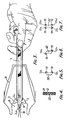
- the spatula shown in Figs. 1 and 2 comprises an elongate body formed by components 1 and 4.
- Component 1 comprises spaced longitudinal side pieces 1a and 1b joined by transverse strips 1c.
- Component 4 is held between the side pieces 1a, 1b by the strips 1c and is longitudinally slidable relative to the component 1.
- Component 1 has at one end thereof (called the "distal" end) opposite side lobes 2 and 3 having leading scraping edges 2a, 3a of concave arcuate form.
- the inner component 4 has a distal end portion 4a which projects centrally between the side lobes 2 and 3.
- the said projecting end portion 4a has side scraping edges 4b, 4c which are contiguous with and form forward extensions of the concave scraping edges 2a, 3a respectively of the side lobes.
- the distance over which the end portion 4a projects forwardly from the side lobes 2 and 3 can be varied.
- a button 5 which projects through a slot 6 in component 1. The button facilitates the manual sliding motion of component 4 relative to component 1.
- FIG. 3 A cervix is represented at 8. Vaginal dilation is effected by a conventional speculum 9.
- the spatula is presented to the cervix with the inner component 4 in its retracted position which is represented in full line.
- the scraping edges 2a, 3a of the two opposite side lobes 2 and 3 contact the ectocervix, which then follows the concave arcuate profile of these scraping edges as shown at 11.
- the component 4 is then advanced axially relative to component 1 by exerting forward pressure against the button 5, thereby causing the central scraper portion 4a to advance further along the cervical canal 10 to the position shown in broken line.
- each side edge of the central scraper portion 4a and the leading concave edge of the corresponding side lobe remain contiguous extensions one of the other so that they together form uninterrupted scraping edges. Rotation of the spatula through 180° then results in scraping of the ectocervix and the adjacent part of the cervical canal through 360°.
- the proximal end portion of the component 1 of the spatula shown in Figs. 1 and 2 forms a fixed portion 7 which can be used for taking vaginal smears.
- Fig. 4 shows the body portion of another spatula wherein the component 22 carrying the central scraper portion has V-section grooves 12 in its longitudinal edge faces and the other component 21 has edge faces of complementary profile so that the edges of the two components interengage, forming a slide joint.
- Figs. 5 to 7 show different possible transverse cross-sectional shapings of this central projection, which provide such edges.
- the transverse cross-section of the projection 32 is such that it has convergent side edge faces providing two acutely-angled scraping edges 32a, 32b at the ends of its wider face. Rotation of the spatula in one direction produces a build-up of smear 13 on one edge and subsequent rotation in the opposite direction produces a further smear 13 on the other edge.
- FIG. 6 shows a central projection 42 having parallel chamfered edge faces to provide, as viewed in transverse section, two acutely-angled scraping edges 42a, 42b located at two diagonally opposed corners of the section.
- two smears 13 can simultaneously be obtained by turning the spatula in one direction.
- the central projection 23 has V-section grooves along its edge faces so that the projection has four acutely-angled scraping edges 23a-23d by which four smear samples 13 can be obtained from within the cervical canal by turning the spatula first in one direction and then in the other.
- the V-section grooves can be continued along the component for inter-engagement with guide faces of complementary shape in the other component as has been described with reference to Fig. 4.
- grooves of U-section can be provided.
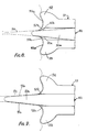
- FIGs. 8 and 9 show a preferred spatula according to the invention wherein the central projection formed by the distal end portion 50a of a first spatula component 50 is tapered so that its side scraping edges at 50b, 50c converge towards the tip of the projection.
- the tapering of this distal end portion facilitates its entry into a cervical canal 54, which usually has a progressively diminishing diameter.
- the second component 51 of the spatula provides opposed side lobes 52, 53 with concave scraping edges 52a, 53a.
- the side lobes have tongue portions 52b, 53b which bear against the convergent side edges of the tapering distal end portion 50a of the first spatula component 50.
- the spatula can be presented with the said central projection in fully advanced position and the spatula component carrying this projection can be allowed to slide back relative to the other component to some extent depending on the degree of resistance offered by the walls of the cervical canal.
Landscapes
- Health & Medical Sciences (AREA)
- Life Sciences & Earth Sciences (AREA)
- Surgery (AREA)
- Public Health (AREA)
- Reproductive Health (AREA)
- Engineering & Computer Science (AREA)
- Biomedical Technology (AREA)
- Heart & Thoracic Surgery (AREA)
- Medical Informatics (AREA)
- Molecular Biology (AREA)
- Gynecology & Obstetrics (AREA)
- Animal Behavior & Ethology (AREA)
- General Health & Medical Sciences (AREA)
- Pathology (AREA)
- Veterinary Medicine (AREA)
- Orthopedics, Nursing, And Contraception (AREA)
- Fats And Perfumes (AREA)
- Steroid Compounds (AREA)
- Medicines Containing Material From Animals Or Micro-Organisms (AREA)
- Pyrane Compounds (AREA)
- Endoscopes (AREA)
- Surgical Instruments (AREA)
- Absorbent Articles And Supports Therefor (AREA)
Claims (5)
Priority Applications (1)
| Application Number | Priority Date | Filing Date | Title |
|---|---|---|---|
| AT83304913T ATE27680T1 (de) | 1982-09-14 | 1983-08-25 | Gynaekologischer spatel. |
Applications Claiming Priority (2)
| Application Number | Priority Date | Filing Date | Title |
|---|---|---|---|
| GB8226118 | 1982-09-14 | ||
| GB8226118 | 1982-09-14 |
Publications (3)
| Publication Number | Publication Date |
|---|---|
| EP0106461A2 EP0106461A2 (de) | 1984-04-25 |
| EP0106461A3 EP0106461A3 (en) | 1985-01-30 |
| EP0106461B1 true EP0106461B1 (de) | 1987-06-10 |
Family
ID=10532886
Family Applications (1)
| Application Number | Title | Priority Date | Filing Date |
|---|---|---|---|
| EP83304913A Expired EP0106461B1 (de) | 1982-09-14 | 1983-08-25 | Gynäkologischer Spatel |
Country Status (6)
| Country | Link |
|---|---|
| EP (1) | EP0106461B1 (de) |
| JP (1) | JPS5964033A (de) |
| AT (1) | ATE27680T1 (de) |
| AU (1) | AU1909483A (de) |
| DE (1) | DE3371965D1 (de) |
| ZA (1) | ZA836576B (de) |
Families Citing this family (5)
| Publication number | Priority date | Publication date | Assignee | Title |
|---|---|---|---|---|
| BR9307275A (pt) * | 1992-10-23 | 1999-06-01 | Lonsten Pty Ltd | Sonda endocervical para extremidade dianteira de amostragem de esfregaço de papanicolaou |
| AT401866B (de) * | 1993-09-27 | 1996-12-27 | Kosian Walter Dr | Vorrichtung zur entnahme von proben |
| WO1999025251A1 (en) * | 1997-11-14 | 1999-05-27 | Harwill Industries (Pty.) Ltd. | Medical spatula |
| GB0015304D0 (en) | 2000-06-23 | 2000-08-16 | Cellpath Plc | Improved medical sampler |
| GB0108554D0 (en) | 2001-04-05 | 2001-05-23 | George Samuel | Health screening device |
Family Cites Families (5)
| Publication number | Priority date | Publication date | Assignee | Title |
|---|---|---|---|---|
| US3583390A (en) * | 1968-08-12 | 1971-06-08 | Mario Enrique Jascalevich | Biopsy device |
| US3774590A (en) * | 1970-04-01 | 1973-11-27 | B Mcdonald | Uterine specimen collecting method |
| GB1429689A (en) * | 1973-06-06 | 1976-03-24 | Armour Pharma | Devices for obtaining cytologic samples |
| US4016865A (en) * | 1975-09-17 | 1977-04-12 | Fredricks Richard N | Cervical-vaginal spatula |
| US4318414A (en) * | 1977-05-09 | 1982-03-09 | Ovutime, Inc. | Probe for obtaining cervical mucus |
-
1983
- 1983-08-25 AT AT83304913T patent/ATE27680T1/de not_active IP Right Cessation
- 1983-08-25 EP EP83304913A patent/EP0106461B1/de not_active Expired
- 1983-08-25 DE DE8383304913T patent/DE3371965D1/de not_active Expired
- 1983-09-05 ZA ZA836576A patent/ZA836576B/xx unknown
- 1983-09-12 JP JP58166808A patent/JPS5964033A/ja active Pending
- 1983-09-13 AU AU19094/83A patent/AU1909483A/en not_active Abandoned
Also Published As
| Publication number | Publication date |
|---|---|
| DE3371965D1 (en) | 1987-07-16 |
| EP0106461A3 (en) | 1985-01-30 |
| ATE27680T1 (de) | 1987-06-15 |
| JPS5964033A (ja) | 1984-04-11 |
| ZA836576B (en) | 1984-04-25 |
| AU1909483A (en) | 1984-03-22 |
| EP0106461A2 (de) | 1984-04-25 |
Similar Documents
| Publication | Publication Date | Title |
|---|---|---|
| US4016865A (en) | Cervical-vaginal spatula | |
| US6607494B1 (en) | Mucosal sampler | |
| US3554185A (en) | Cervical biopsy-sampling instrument | |
| US5476104A (en) | Cervical and endometrial biopsy instrument | |
| US4981143A (en) | Cell sampler | |
| US4441509A (en) | Endometrial sampling device | |
| US4384587A (en) | Spatula for collecting cervical cancer cells | |
| US4641662A (en) | Endocervical curette system | |
| CA1045492A (en) | Vacuum curet | |
| US20140221870A1 (en) | Biopsy needle system and method for obtaining a tissue biopsy specimen | |
| DE69100688T2 (de) | Instrument zur endo- und ektocervikalen probennahme. | |
| EP1913878A2 (de) | Drehvorrichtung zum Entnehmen von Schleim zur Untersuchung | |
| US20150018714A1 (en) | Step-shaped endometrial curette | |
| CA2310254A1 (en) | Medical spatula | |
| EP0594786A1 (de) | Probenahmevorrichtung für abstriche | |
| US3847143A (en) | Speculum | |
| EP0106461A2 (de) | Gynäkologischer Spatel | |
| JPH10137248A (ja) | 吸引生検具 | |
| US7942896B2 (en) | Forceps and collection assembly and related methods of use and manufacture | |
| CN210844857U (zh) | 一种神经外科用引流管及其组件 | |
| CN108969160B (zh) | 一种椎间运动保留装置及其一体式植入器械和植入方法 | |
| CA2146574A1 (en) | Endocervical probe for pap smear sampling head | |
| EP1357839A1 (de) | Medizinischer spatel | |
| AU655495B2 (en) | Pap smear sampling device | |
| JP7623366B2 (ja) | 手術器具、手術器具を製造する方法および手術器具の切断工具を形成するための回転ジョイントの使用 |
Legal Events
| Date | Code | Title | Description |
|---|---|---|---|
| PUAI | Public reference made under article 153(3) epc to a published international application that has entered the european phase |
Free format text: ORIGINAL CODE: 0009012 |
|
| AK | Designated contracting states |
Designated state(s): AT BE CH DE FR GB IT LI LU NL SE |
|
| PUAL | Search report despatched |
Free format text: ORIGINAL CODE: 0009013 |
|
| AK | Designated contracting states |
Designated state(s): AT BE CH DE FR GB IT LI LU NL SE |
|
| 17P | Request for examination filed |
Effective date: 19850723 |
|
| 17Q | First examination report despatched |
Effective date: 19860513 |
|
| GRAA | (expected) grant |
Free format text: ORIGINAL CODE: 0009210 |
|
| AK | Designated contracting states |
Kind code of ref document: B1 Designated state(s): AT BE CH DE FR GB IT LI LU NL SE |
|
| PG25 | Lapsed in a contracting state [announced via postgrant information from national office to epo] |
Ref country code: NL Effective date: 19870610 Ref country code: LI Effective date: 19870610 Ref country code: IT Free format text: LAPSE BECAUSE OF FAILURE TO SUBMIT A TRANSLATION OF THE DESCRIPTION OR TO PAY THE FEE WITHIN THE PRESCRIBED TIME-LIMIT;WARNING: LAPSES OF ITALIAN PATENTS WITH EFFECTIVE DATE BEFORE 2007 MAY HAVE OCCURRED AT ANY TIME BEFORE 2007. THE CORRECT EFFECTIVE DATE MAY BE DIFFERENT FROM THE ONE RECORDED. Effective date: 19870610 Ref country code: FR Free format text: THE PATENT HAS BEEN ANNULLED BY A DECISION OF A NATIONAL AUTHORITY Effective date: 19870610 Ref country code: CH Effective date: 19870610 Ref country code: BE Effective date: 19870610 Ref country code: AT Effective date: 19870610 |
|
| REF | Corresponds to: |
Ref document number: 27680 Country of ref document: AT Date of ref document: 19870615 Kind code of ref document: T |
|
| PG25 | Lapsed in a contracting state [announced via postgrant information from national office to epo] |
Ref country code: SE Effective date: 19870630 |
|
| REF | Corresponds to: |
Ref document number: 3371965 Country of ref document: DE Date of ref document: 19870716 |
|
| PG25 | Lapsed in a contracting state [announced via postgrant information from national office to epo] |
Ref country code: LU Free format text: LAPSE BECAUSE OF NON-PAYMENT OF DUE FEES Effective date: 19870831 |
|
| REG | Reference to a national code |
Ref country code: CH Ref legal event code: PL |
|
| EN | Fr: translation not filed | ||
| NLV1 | Nl: lapsed or annulled due to failure to fulfill the requirements of art. 29p and 29m of the patents act | ||
| PLBE | No opposition filed within time limit |
Free format text: ORIGINAL CODE: 0009261 |
|
| STAA | Information on the status of an ep patent application or granted ep patent |
Free format text: STATUS: NO OPPOSITION FILED WITHIN TIME LIMIT |
|
| PG25 | Lapsed in a contracting state [announced via postgrant information from national office to epo] |
Ref country code: DE Effective date: 19880503 |
|
| 26N | No opposition filed | ||
| PGFP | Annual fee paid to national office [announced via postgrant information from national office to epo] |
Ref country code: GB Payment date: 19900822 Year of fee payment: 8 |
|
| PG25 | Lapsed in a contracting state [announced via postgrant information from national office to epo] |
Ref country code: GB Effective date: 19910825 |
|
| GBPC | Gb: european patent ceased through non-payment of renewal fee |