EP0106481A2 - Packung des Abgasschalldämpfers von Kraftfahrzeugen - Google Patents
Packung des Abgasschalldämpfers von Kraftfahrzeugen Download PDFInfo
- Publication number
- EP0106481A2 EP0106481A2 EP83305077A EP83305077A EP0106481A2 EP 0106481 A2 EP0106481 A2 EP 0106481A2 EP 83305077 A EP83305077 A EP 83305077A EP 83305077 A EP83305077 A EP 83305077A EP 0106481 A2 EP0106481 A2 EP 0106481A2
- Authority
- EP
- European Patent Office
- Prior art keywords
- silencer
- casing
- air flow
- strand
- fibres
- Prior art date
- Legal status (The legal status is an assumption and is not a legal conclusion. Google has not performed a legal analysis and makes no representation as to the accuracy of the status listed.)
- Granted
Links
Images

Classifications
-
- F—MECHANICAL ENGINEERING; LIGHTING; HEATING; WEAPONS; BLASTING
- F01—MACHINES OR ENGINES IN GENERAL; ENGINE PLANTS IN GENERAL; STEAM ENGINES
- F01N—GAS-FLOW SILENCERS OR EXHAUST APPARATUS FOR MACHINES OR ENGINES IN GENERAL; GAS-FLOW SILENCERS OR EXHAUST APPARATUS FOR INTERNAL-COMBUSTION ENGINES
- F01N13/00—Exhaust or silencing apparatus characterised by constructional features
- F01N13/18—Construction facilitating manufacture, assembly, or disassembly
-
- F—MECHANICAL ENGINEERING; LIGHTING; HEATING; WEAPONS; BLASTING
- F01—MACHINES OR ENGINES IN GENERAL; ENGINE PLANTS IN GENERAL; STEAM ENGINES
- F01N—GAS-FLOW SILENCERS OR EXHAUST APPARATUS FOR MACHINES OR ENGINES IN GENERAL; GAS-FLOW SILENCERS OR EXHAUST APPARATUS FOR INTERNAL-COMBUSTION ENGINES
- F01N1/00—Silencing apparatus characterised by method of silencing
- F01N1/24—Silencing apparatus characterised by method of silencing by using sound-absorbing materials
-
- F—MECHANICAL ENGINEERING; LIGHTING; HEATING; WEAPONS; BLASTING
- F01—MACHINES OR ENGINES IN GENERAL; ENGINE PLANTS IN GENERAL; STEAM ENGINES
- F01N—GAS-FLOW SILENCERS OR EXHAUST APPARATUS FOR MACHINES OR ENGINES IN GENERAL; GAS-FLOW SILENCERS OR EXHAUST APPARATUS FOR INTERNAL-COMBUSTION ENGINES
- F01N2310/00—Selection of sound absorbing or insulating material
- F01N2310/02—Mineral wool, e.g. glass wool, rock wool, asbestos or the like
-
- F—MECHANICAL ENGINEERING; LIGHTING; HEATING; WEAPONS; BLASTING
- F01—MACHINES OR ENGINES IN GENERAL; ENGINE PLANTS IN GENERAL; STEAM ENGINES
- F01N—GAS-FLOW SILENCERS OR EXHAUST APPARATUS FOR MACHINES OR ENGINES IN GENERAL; GAS-FLOW SILENCERS OR EXHAUST APPARATUS FOR INTERNAL-COMBUSTION ENGINES
- F01N2450/00—Methods or apparatus for fitting, inserting or repairing different elements
- F01N2450/06—Inserting sound absorbing material into a chamber
Definitions
- This invention relates to the packing of automobile exhaust silencers.
- Such silencers contain packing in order to assist in silencing exhaust gases from the vehicle engine by virtue of conversion of kinetic energy of the exhaust gases into mechanical displacements of the packing and thus heating thereof.
- One of the materials used to pack such silencers is glass fibre fluffed up into a wool-like consistency. This material can be produced by chopping continuous strands of glass fibre.
- glass fibre material in wool-like form has been fed into a hopper, from which it passes along ducts before being metered into individual quantities, each suitable for packing one silencer.
- the material has been prone to clog in the ducts and this has made the accurate metering of the material difficult, if the expense of weigh pans is to be avoided.
- the invention provides a method of packing a silencer casing which comprises establishing an air flow into and out of the silencer casing, chopping into discrete lengths a strand consisting of a plurality of continuous glass fibres, and allowing them to be carried into the silencer casing in the air flow.
- the strand, or roving advantageously contains at least one hundred, preferably at least a thousand, individual continuous glass fibres whose diameter is advantageously less than 30 microns and preferably less than 15 microns.
- the fibres- of the roving are preferably non- twisted.
- the roving is driven from two rollers in contact with each other; this makes it easy to meter accurate quantities of glass fibre into each silencer casing, since it is only necessary to leave the rollers running for a certain period of time in order to know exactly how much glass fibre has been fed into the silencer.
- a roller may also be provided for chopping the fibres, and they may be projected with the assistance of an air blast.
- the air flow leaves the silencer via a perforated tube of the silencer.
- the air flows through a restriction, the diameter of which is less than one inch, before it enters the casing: the I fibre. is. fluffedup in the region of turbulence so created.
- the restriction may be connected to a tapering tubular member at its narrow end, the wide end of which draws the fibers in.
- the taper may be from 15° to 75 0 included angle.
- the air flow may be produced by means of a vacuum applied to where the air flow leaves the casing.
- the vacuum applied to the silencer casing may be at least one inch of mercury, preferably at least five inches of mercury, and advantageously between seven and a half and twelve and a half inches of mercury.
- the air flow may be established by means of a jet of compressed air which draws fibers into the air flow before it enters the casing.
- the jet preferably feeds into the restriction: it may be inclined at an angle 71 ⁇ 2° to 371 ⁇ 2° to the axis of the tubular member.
- the compressed air' pressure should be at least 70 pounds per square inch.
- the invention also provides a silencer casing packed in accordance with any of the forms of the method of the invention.
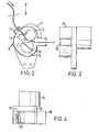
- the first apparatus for packing a silencer casing 1 comprises a vacuum producing apparatus 2, a sealing apparatus 3 and a gun 4.
- the casing of the silencer is circular in section, and one end of it has been closed by an end piece 5, which supports a perforated tube 6 running along the length of the silencer casing.
- the end piece 5 supports a stub pipe 7 which connects to the rest of the exhaust assembly in use.
- a similar end piece bearing a stub pipe is welded to the other end of the silencer when it has been packed. .
- the vacuum producing apparatus has a rubber sealing member 8 which fits tightly around the stub pipe 7.
- the vacuum is produced by means of a centrifugal compressor (not shown) driven by ⁇ forty horse power motor (not shown). This apparatus produces a vacuum of around ten inches of mercury.
- the sealing apparatus 3 likewise includes a sealing member 9 which seals against the open end of the casing and also blocks off the open end of the perforated tube 6, since this must not be filled with any packing material.
- the sealing member has a circular aperture 10 whose diameter is 4 inch.
- the roving fed into the gun 4 consists of around two thousand mono-filamentary continuous glass fibres, whose diameters lie between about six and twelve microns.
- the fibres in the roving are parallel to each other, that is, the roving is not twisted.
- the roving is fed from a spool (not shown) containing a length of about a couple of hundred meters of the roving.
- the gun has an air-powered motor, contained in housing 11, to which rubber roller 12 is coxially attached.
- the roving is driven by means of rubber roller 12 and steel roller 13 which is hard in contact with roller 12.
- the roving is cut into discrete lengths by means of a cutter 14 mounted diametrically through a further roller 15. Every half revolution of roller 15, the roving is severed at the point of contact with roller 12.
- the rollers are ocntained in a housing 16 having an inlet 17 and an outlet 18.
- the air exhaust from the air powered motor is fed into the housing 16 and, since the area of the outlet 18 is much greater than that of the inlet 17, the chopped lengths of roving are projected out of the gun with the aid of an air blast.
- a silencer casing 1 to be filled is fitted onto the vacuum producing apparatus 2 and a sealing apparatus is brought up to the open end of the silencer.
- the vacuum pump is started.
- the gun 4 is then run and left running for a pre-determined period of time. This pre-determined period corresponds to the desired weight of glass fibre it is desired to pack the particular silencer with, and this can be calculated simply from the weight per unit length of the roving and the velocity at which the roving is fed through the gun.
- the chopped lengths of roving projected from the gun are all sucked through the aperture 10 in the sealing member 9 because the vacuum applied at the other end of the silencer casing, and the silencer is gradually filled with glass fibre. It has been found that the fibres of each chopped length of roving separate either before they enter the silencer casing or while they are in the silencer casing (probably the separation mainly takes place within the silencer), and this results in the production of the desired wool-like form of the glass fibre in the silencer.
- the air flow within the silencer will of course be turbulent since it is being sucked through the perforated tube 6. The lengths of fibre do not pass into the tube 6 themselves.
- the invention is of course applicable to any form of silencer, for example, such as the form where exhaust gases make multiple passes of the whole the part of the length of the silencer casing.
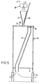
- the second form of apparatus differs from the first in that there is no vacuum required to draw the roving pieces into the silencer, rather they are drawn in carried in an air flow.
- a silencer 20 to be filled is closed at the lower end as seen in the drawing by a closing plate 21 which has an aperture through which a perforated tube 22 of the silencer extends.
- the silencer is mounted on a platform 23 through which air can pass.
- the upper end of the silencer as seen in the drawing is connected to the apparatus, in particular to a closing plate 24 which carries a plug 25 for closing the end of the perforated tube 22.
- the chopped strands of roving are fed into the silencer casing via a tube 26 and conical member 27, the tube 26 being sealed in anaperture in the closing plate 24.
- a gun 28 supplies roving to the wide end of the conical member: the gun 28 is identical to the gun 4 of the first apparatus except that air does not assist in projecting the cut strands of roving from the gun, the cut strands being projected solely be the rotation of the rollers.
- the roving used is the same as the first apparatus.
- a narrow tube 29 opens into the tube 26, and compressed air is supplied to its other end.
- tube 26 three inches long, one half inch diameter
- conical member 27 semi-angle 30°, diameter at wide end, three inches
- the narrow diameter of the tube 26 is important in "fluffing-up" the cut strands of roving, since only with a narrow diameter is sufficient turbulence created in the tube to achieve this. It is believed that the narrow opening 10 in the first apparatus is also responsible for creating the necessary turbulence. The narrower the diameter, the smaller the compressed air pressure or vacuum needed to fluff-up the fibre, but if the diameter is too small, the restriction is prone to clogging.
Landscapes
- Engineering & Computer Science (AREA)
- Chemical & Material Sciences (AREA)
- Combustion & Propulsion (AREA)
- Mechanical Engineering (AREA)
- General Engineering & Computer Science (AREA)
- Exhaust Silencers (AREA)
Applications Claiming Priority (2)
| Application Number | Priority Date | Filing Date | Title |
|---|---|---|---|
| GB8225865 | 1982-09-10 | ||
| GB08225865A GB2127093B (en) | 1982-09-10 | 1982-09-10 | Packing automobile exhaust silencer casing |
Publications (3)
| Publication Number | Publication Date |
|---|---|
| EP0106481A2 true EP0106481A2 (de) | 1984-04-25 |
| EP0106481A3 EP0106481A3 (en) | 1984-07-18 |
| EP0106481B1 EP0106481B1 (de) | 1987-01-21 |
Family
ID=10532835
Family Applications (1)
| Application Number | Title | Priority Date | Filing Date |
|---|---|---|---|
| EP83305077A Expired EP0106481B1 (de) | 1982-09-10 | 1983-09-01 | Packung des Abgasschalldämpfers von Kraftfahrzeugen |
Country Status (5)
| Country | Link |
|---|---|
| EP (1) | EP0106481B1 (de) |
| JP (1) | JPS59131717A (de) |
| CA (1) | CA1240131A (de) |
| DE (1) | DE3369360D1 (de) |
| GB (1) | GB2127093B (de) |
Cited By (7)
| Publication number | Priority date | Publication date | Assignee | Title |
|---|---|---|---|---|
| EP0153100A1 (de) * | 1984-02-14 | 1985-08-28 | Unipart Group Limited | Verfahren und Einrichtung zur Verpackung des Abgasschalldämpfers |
| EP0146249A3 (en) * | 1983-11-18 | 1987-03-25 | Tba Industrial Products Limited | Glass fibre products |
| AU582555B2 (en) * | 1983-11-18 | 1989-04-06 | Tba Industrial Products Limited | Glass fibre products |
| WO2002075122A1 (en) * | 2001-03-16 | 2002-09-26 | Owens Corning | Process for filling a muffler shell with fibrous material |
| WO2003023201A1 (en) * | 2001-09-12 | 2003-03-20 | Owens Corning Composites S.P.R.L. | Muffler shell filling process and muffler filled with fibrous material |
| US6581723B2 (en) * | 2001-08-31 | 2003-06-24 | Owens Corning Composites Sprl | Muffler shell filling process, muffler filled with fibrous material and vacuum filling device |
| US8590155B2 (en) | 2009-06-03 | 2013-11-26 | Ocv Intellectual Capital, Llc | Apparatus for and process of filling a muffler with fibrous material utilizing a directional jet |
Families Citing this family (1)
| Publication number | Priority date | Publication date | Assignee | Title |
|---|---|---|---|---|
| JP6317561B2 (ja) * | 2013-10-16 | 2018-04-25 | 株式会社Subaru | 繊維充填装置および繊維充填方法 |
Family Cites Families (2)
| Publication number | Priority date | Publication date | Assignee | Title |
|---|---|---|---|---|
| GB1279472A (en) * | 1969-10-30 | 1972-06-28 | Harmo Ind Ltd | Improvements in or relating to absorbent devices |
| SE445942B (sv) * | 1982-04-06 | 1986-07-28 | Volvo Ab | Ljuddempare samt sett och anordning for framstellning av denna |
-
1982
- 1982-09-10 GB GB08225865A patent/GB2127093B/en not_active Expired
-
1983
- 1983-09-01 DE DE8383305077T patent/DE3369360D1/de not_active Expired
- 1983-09-01 EP EP83305077A patent/EP0106481B1/de not_active Expired
- 1983-09-09 CA CA000436414A patent/CA1240131A/en not_active Expired
- 1983-09-10 JP JP16737983A patent/JPS59131717A/ja active Pending
Cited By (9)
| Publication number | Priority date | Publication date | Assignee | Title |
|---|---|---|---|---|
| EP0146249A3 (en) * | 1983-11-18 | 1987-03-25 | Tba Industrial Products Limited | Glass fibre products |
| AU582555B2 (en) * | 1983-11-18 | 1989-04-06 | Tba Industrial Products Limited | Glass fibre products |
| EP0153100A1 (de) * | 1984-02-14 | 1985-08-28 | Unipart Group Limited | Verfahren und Einrichtung zur Verpackung des Abgasschalldämpfers |
| WO2002075122A1 (en) * | 2001-03-16 | 2002-09-26 | Owens Corning | Process for filling a muffler shell with fibrous material |
| US6581723B2 (en) * | 2001-08-31 | 2003-06-24 | Owens Corning Composites Sprl | Muffler shell filling process, muffler filled with fibrous material and vacuum filling device |
| WO2003023201A1 (en) * | 2001-09-12 | 2003-03-20 | Owens Corning Composites S.P.R.L. | Muffler shell filling process and muffler filled with fibrous material |
| US6607052B2 (en) | 2001-09-12 | 2003-08-19 | Owens Corning Composites Sprl | Muffler shell filling process and muffler filled with fibrous material |
| CN1316149C (zh) * | 2001-09-12 | 2007-05-16 | 欧文斯康宁合成物有限公司 | 消音器外壳填充方法以及充填纤维材料的消音器 |
| US8590155B2 (en) | 2009-06-03 | 2013-11-26 | Ocv Intellectual Capital, Llc | Apparatus for and process of filling a muffler with fibrous material utilizing a directional jet |
Also Published As
| Publication number | Publication date |
|---|---|
| CA1240131A (en) | 1988-08-09 |
| EP0106481B1 (de) | 1987-01-21 |
| DE3369360D1 (en) | 1987-02-26 |
| GB2127093B (en) | 1986-01-29 |
| GB2127093A (en) | 1984-04-04 |
| EP0106481A3 (en) | 1984-07-18 |
| JPS59131717A (ja) | 1984-07-28 |
Similar Documents
| Publication | Publication Date | Title |
|---|---|---|
| EP0146249B1 (de) | Glasfaserprodukte | |
| EP0106481A2 (de) | Packung des Abgasschalldämpfers von Kraftfahrzeugen | |
| US4202163A (en) | Spinning process and apparatus | |
| DE1542266C3 (de) | Vorrichtung zum Abscheiden von in einem strömenden gasförmigen Medium mitgefühlten flüssigen und festen Partikeln | |
| EP0457986A1 (de) | Verfahren zum Einführen eines langgestreckten flexiblen Körpers in eine Durchführung | |
| EP0153100B1 (de) | Verfahren und Einrichtung zur Verpackung des Abgasschalldämpfers | |
| US5069582A (en) | Vacuum producing device | |
| GB2158001A (en) | A moulding for inserting into an exhaust silencer casing | |
| GB2127929A (en) | Apparatus for use in reviving a fluid passage | |
| EP0183543A2 (de) | Vorrichtung zum Schneiden von länglichem Material in kürzere Längen | |
| CN1448556A (zh) | 在纤维材料输送时分离输送空气的装置 | |
| JPH0637264B2 (ja) | 織物用繊維ストランドを圧縮し且フィード挾持部内へ自動的に導入する装置 | |
| US6056798A (en) | Multi stage separator | |
| EP0096557A1 (de) | Bestimmung des Sauerstoff- und Brennstoffgehaltes in einem Gas | |
| US2581467A (en) | Device for cutting staple fiber | |
| US4073129A (en) | Method and apparatus for manufacture of yarn | |
| US4383349A (en) | Opening bonded glass fiber bundles | |
| US20060087910A1 (en) | Water injection method and apparatus for concrete mixer | |
| US20060172644A1 (en) | A Mat with yarns made of alkali-resistant glass | |
| US6758998B2 (en) | Method and device for inserting fibers in expanded form into a cavity or depositing them on a surface | |
| US3985053A (en) | Device for the opening and conveyance of freshly cut staple fiber bundles | |
| CN204752942U (zh) | 一种气流输送纤维的管线切割机 | |
| CN219830340U (zh) | 一种立磨生产发送在线取样装置 | |
| JPS60125895A (ja) | グラスフアイバー充填方法およびその装置 | |
| EP0750060B1 (de) | Vorrichtung zur Bestimmung von Unregelmässigkeiten der Masse eines Faserbandes |
Legal Events
| Date | Code | Title | Description |
|---|---|---|---|
| PUAI | Public reference made under article 153(3) epc to a published international application that has entered the european phase |
Free format text: ORIGINAL CODE: 0009012 |
|
| AK | Designated contracting states |
Designated state(s): DE FR GB IT |
|
| PUAL | Search report despatched |
Free format text: ORIGINAL CODE: 0009013 |
|
| AK | Designated contracting states |
Designated state(s): DE FR GB IT |
|
| 17P | Request for examination filed |
Effective date: 19841224 |
|
| GRAA | (expected) grant |
Free format text: ORIGINAL CODE: 0009210 |
|
| AK | Designated contracting states |
Kind code of ref document: B1 Designated state(s): DE FR GB IT |
|
| ITF | It: translation for a ep patent filed | ||
| REF | Corresponds to: |
Ref document number: 3369360 Country of ref document: DE Date of ref document: 19870226 |
|
| ET | Fr: translation filed | ||
| PLBE | No opposition filed within time limit |
Free format text: ORIGINAL CODE: 0009261 |
|
| STAA | Information on the status of an ep patent application or granted ep patent |
Free format text: STATUS: NO OPPOSITION FILED WITHIN TIME LIMIT |
|
| 26N | No opposition filed | ||
| PGFP | Annual fee paid to national office [announced via postgrant information from national office to epo] |
Ref country code: GB Payment date: 19890831 Year of fee payment: 7 |
|
| PGFP | Annual fee paid to national office [announced via postgrant information from national office to epo] |
Ref country code: FR Payment date: 19900727 Year of fee payment: 8 |
|
| PG25 | Lapsed in a contracting state [announced via postgrant information from national office to epo] |
Ref country code: GB Effective date: 19900901 |
|
| ITTA | It: last paid annual fee | ||
| PGFP | Annual fee paid to national office [announced via postgrant information from national office to epo] |
Ref country code: DE Payment date: 19901130 Year of fee payment: 8 |
|
| GBPC | Gb: european patent ceased through non-payment of renewal fee | ||
| PG25 | Lapsed in a contracting state [announced via postgrant information from national office to epo] |
Ref country code: FR Effective date: 19920529 |
|
| PG25 | Lapsed in a contracting state [announced via postgrant information from national office to epo] |
Ref country code: DE Effective date: 19920602 |
|
| REG | Reference to a national code |
Ref country code: FR Ref legal event code: ST |
|
| P01 | Opt-out of the competence of the unified patent court (upc) registered |
Effective date: 20230529 |