EP0106525B1 - Verfahren zur Herstellung eines Dorns mit Seitentasche, ohne Schweissen - Google Patents
Verfahren zur Herstellung eines Dorns mit Seitentasche, ohne Schweissen Download PDFInfo
- Publication number
- EP0106525B1 EP0106525B1 EP83305325A EP83305325A EP0106525B1 EP 0106525 B1 EP0106525 B1 EP 0106525B1 EP 83305325 A EP83305325 A EP 83305325A EP 83305325 A EP83305325 A EP 83305325A EP 0106525 B1 EP0106525 B1 EP 0106525B1
- Authority
- EP
- European Patent Office
- Prior art keywords
- bore
- land
- bar
- smaller
- plane
- Prior art date
- Legal status (The legal status is an assumption and is not a legal conclusion. Google has not performed a legal analysis and makes no representation as to the accuracy of the status listed.)
- Expired
Links
- 238000000034 method Methods 0.000 title claims abstract description 11
- 238000003754 machining Methods 0.000 claims abstract description 23
- 239000002184 metal Substances 0.000 claims description 10
- 230000000149 penetrating effect Effects 0.000 claims description 10
- 230000002093 peripheral effect Effects 0.000 claims description 9
- 230000004048 modification Effects 0.000 description 3
- 238000012986 modification Methods 0.000 description 3
- 238000010276 construction Methods 0.000 description 2
- 229910000831 Steel Inorganic materials 0.000 description 1
- 238000005520 cutting process Methods 0.000 description 1
- 238000004519 manufacturing process Methods 0.000 description 1
- 229910001220 stainless steel Inorganic materials 0.000 description 1
- 239000010935 stainless steel Substances 0.000 description 1
- 239000010959 steel Substances 0.000 description 1
- 238000003466 welding Methods 0.000 description 1
Images

Classifications
-
- B—PERFORMING OPERATIONS; TRANSPORTING
- B23—MACHINE TOOLS; METAL-WORKING NOT OTHERWISE PROVIDED FOR
- B23P—METAL-WORKING NOT OTHERWISE PROVIDED FOR; COMBINED OPERATIONS; UNIVERSAL MACHINE TOOLS
- B23P13/00—Making metal objects by operations essentially involving machining but not covered by a single other subclass
-
- E—FIXED CONSTRUCTIONS
- E21—EARTH OR ROCK DRILLING; MINING
- E21B—EARTH OR ROCK DRILLING; OBTAINING OIL, GAS, WATER, SOLUBLE OR MELTABLE MATERIALS OR A SLURRY OF MINERALS FROM WELLS
- E21B23/00—Apparatus for displacing, setting, locking, releasing or removing tools, packers or the like in boreholes or wells
- E21B23/03—Apparatus for displacing, setting, locking, releasing or removing tools, packers or the like in boreholes or wells for setting the tools into, or removing the tools from, laterally offset landing nipples or pockets
-
- Y—GENERAL TAGGING OF NEW TECHNOLOGICAL DEVELOPMENTS; GENERAL TAGGING OF CROSS-SECTIONAL TECHNOLOGIES SPANNING OVER SEVERAL SECTIONS OF THE IPC; TECHNICAL SUBJECTS COVERED BY FORMER USPC CROSS-REFERENCE ART COLLECTIONS [XRACs] AND DIGESTS
- Y10—TECHNICAL SUBJECTS COVERED BY FORMER USPC
- Y10S—TECHNICAL SUBJECTS COVERED BY FORMER USPC CROSS-REFERENCE ART COLLECTIONS [XRACs] AND DIGESTS
- Y10S138/00—Pipes and tubular conduits
- Y10S138/11—Shape
-
- Y—GENERAL TAGGING OF NEW TECHNOLOGICAL DEVELOPMENTS; GENERAL TAGGING OF CROSS-SECTIONAL TECHNOLOGIES SPANNING OVER SEVERAL SECTIONS OF THE IPC; TECHNICAL SUBJECTS COVERED BY FORMER USPC CROSS-REFERENCE ART COLLECTIONS [XRACs] AND DIGESTS
- Y10—TECHNICAL SUBJECTS COVERED BY FORMER USPC
- Y10S—TECHNICAL SUBJECTS COVERED BY FORMER USPC CROSS-REFERENCE ART COLLECTIONS [XRACs] AND DIGESTS
- Y10S29/00—Metal working
- Y10S29/026—Method or apparatus with machining
-
- Y—GENERAL TAGGING OF NEW TECHNOLOGICAL DEVELOPMENTS; GENERAL TAGGING OF CROSS-SECTIONAL TECHNOLOGIES SPANNING OVER SEVERAL SECTIONS OF THE IPC; TECHNICAL SUBJECTS COVERED BY FORMER USPC CROSS-REFERENCE ART COLLECTIONS [XRACs] AND DIGESTS
- Y10—TECHNICAL SUBJECTS COVERED BY FORMER USPC
- Y10T—TECHNICAL SUBJECTS COVERED BY FORMER US CLASSIFICATION
- Y10T29/00—Metal working
- Y10T29/49—Method of mechanical manufacture
- Y10T29/49995—Shaping one-piece blank by removing material
- Y10T29/49996—Successive distinct removal operations
Definitions
- This invention relates to a method of producing side-pocket mandrels free of welds.
- Mandrels having offset side pockets with seatings for flow control valves to be placed in and removed from the side pockets are interposed in a string of well tubing, the main bores of the mandrels being aligned with and generally of the same diameter as the bore of the well tubing.
- the valves are installed in or removed from the seatings therefor in the side pockets by a valve-handling apparatus or kickover tool, means being provided for moving the apparatus through the tubing and mandrels, the latter accommodating at an upper or lower level therein orienting sleeves adapted to guide the valve-handling apparatus into an attitude relative to the valve seating appropriate for installing a valve therein or removing a valve therefrom.
- a window has been formed in the side of an elongate tubular body by cutting a segment out of the wall of said body and a fabricated insert has been substituted for the segment and has been welded in the window.
- US-A-2 824 525 discloses a mandrel for receiving gas lift valves in lateral offset portions thereof comprising a tubular body 10 from which an opening is cut-out and a tubular receiver 14 is installed in said opening and is welded in place.
- adjacent tubular. members have been joined together using circumferential butt welds.
- the object of the present invention is to provide a method of producing side-pocket mandrels in which welding is entirely dispensed with and the resulting mandrels are free of welds and thus not subject to the failures hitherto directly attributable to welds.
- a method of producing a side-pocket mandrel comprises
- a method of producing a side-pocket mandrel comprises
- a method of producing a side-pocket mandrel comprises
- a side-pocket mandrel is produced by one of the methods described in next- preceding three paragraphs.
- a side pocket mandrel is formed by axially boring a cylindrical bar of metal, for example of stainless steel or other steels capable of being used in the manufacturing of a mandrel, the bar being of predetermined length and diameter from each of the two ends thereof to predetermined depths to leave a land between the blind bores 8.
- a bore 10 of smaller diameter than said blind bores 8 is formed by boring through said land from end to end thereof.
- the smaller bore 10 is axially offset from but parallel to said blind bores 8.
- a discriminator and valve pocket are formed in the remainder of the land by machining through said land by mechanical action or by electro-erosion forming firstly a bore 14 which is symmetrical about a diametrical plane of said smaller bore 10 and which is of semi-circular arch periphery from one end of said land with the plane and parallel flanks 18 thereof penetrating said smaller bore 10 and effectively forming a window of arcuate segmental shape in the periphery of the smaller bore 10 thus forming the discriminator and then secondly continuing the machining into a full bore of predetermined peripheral shape forming the valve pocket 16 separated from and axially parallel to said smaller bore 10 and emerging from the other end of the land.
- a series of holes 20 are formed through the bar wall 22 in a chordal plane and intersecting said valve pocket 16. Both ends of the bar are swaged to provide end lengths 24 of lesser external diameter and axially aligned with said smaller bore 10 and the bores in said end lengths 24 are trued to match said smaller bore 10. Adjacent to the inside end of the end piece next to the diacriminator, an orienting sleeve 26 is machined by mechanical action or electro-erosion, said end to be uppermost or lowermost as required when the side mandrel is operative.
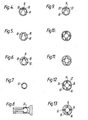
- the depth of land left at the first stage after boring into the bar from both ends can vary depending on whether a short discriminator (Fig. 1) or long discriminator (Fig. 2) is required.
- the smaller bore 10 is coaxial with the blind bores and more than one side pocket 12 is formed, for example (Fig. 3) four spaced at 90 degrees to each other, each pocket having a discriminator and valve pocket 16 with holes 20.
- the side pocket mandrel is formed by axially boring a cylindrical bar of metal of predetermined length and diameter from one end thereof to a predetermined depth to leave a land between the blind bore 8 and the opposite end of the bars.
- a bore 10 of smaller diameter than said blind bore 8 is formed by boring through said land from end to end thereof.
- the smaller bore 10 is axially offset from but parallel to said blind bore 8.
- a discriminator and valve pocket are formed in the remainder of the land by machining through said land beyond a predetermined depth from said opposite end by mechanical action or by electro-erosion forming firstly a bore 14 which is symmetrical about a diametrical plane ' of said smaller bore 10 and which is of semi-circular arch periphery from one end of said land with the plane and parallel flanks 18 thereof penetrating said smaller bore 10 and effectively forming a window of arcuate segmental shape in the periphery of the smaller bore 10 thus forming the discriminator and then secondly continuing the machining into a full bore of predetermined peripheral shape forming the valve pocket 16 separated from and axially parallel to said smaller bore 10 and emerging from the other end of the land into said larger bore.
- a series of holes 20 are formed through the bar wall 22 in a chordal plane and intersect said valve pocket 16.
- the larger bore end of the bar is swaged to provide an end length 24 of lesser external diameter and axially aligned with said smaller bore 10 and the bore in said swaged end length 24 is trued to match said smaller bore 10.
- the depth of land left at the first stage after boring into the bar from both ends can vary depending on whether a short discriminator (Fig. 1) or long discriminator (Fig. 2) is required.
- the smaller bore 10 is coaxial with the blind bores and more than one side pocket 12 is formed, for example (Fig. 3) four spaced at 90 degrees to each other, each pocket having a discriminator and valve pocket 16 with holes 20.
- the side pocket mandrel is formed by boring axially offset from end to end leaving a chordal land a cylindrical bar of metal of predetermined length and diameter.
- a discriminator and valve pocket are formed by machining through said land beyond a predetermined depth from said opposite ends by mechanical action or by electro-erosion forming firstly a bore 14 which is symmetrical about a diametrical plane of said bore 10 and which is of semi-circular arch periphery from one end of said land with the plane and parallel flanks 18 thereof penetrating said bore 10 and effectively forming a window of arcuate segmental shape in the periphery of the bore 10 thus forming the discriminator and then secondly continuing the machining into a full bore of predetermined peripheral shape forming the valve pocket 16 separated from and axially parallel to said bore 10 and emerging from the other end of the land.
- a series of holes 20 are formed through the bar wall 22 in a chordal plane and intersect said valve pocket 16.
- the chordal land over said predetermined depths from each end of the bar are machined away to provide end lengths 24 of lesser external diameter.
- Adjacent to the inside end of the end piece next to the discriminator, an orienting sleeve 26 is machined by mechanical action or electro-erosion, said end to be uppermost or lowermost as required when the side mandrel is operative.
- the predetermined depth of land left at one end at the first stage after boring into the bar from one end can vary depending on whether a short discriminator (Fig. 1) or long discriminator (Fig. 2) is required.
- the bore 10 is coaxial with bar and more than one side pocket 12 is formed, for example (Fig. 3) four spaced at 90 degrees to each other, each pocket having a discriminator and valve pocket 16 with holes 20.
Landscapes
- Engineering & Computer Science (AREA)
- Geology (AREA)
- Life Sciences & Earth Sciences (AREA)
- Mining & Mineral Resources (AREA)
- Physics & Mathematics (AREA)
- Environmental & Geological Engineering (AREA)
- Fluid Mechanics (AREA)
- Mechanical Engineering (AREA)
- General Life Sciences & Earth Sciences (AREA)
- Geochemistry & Mineralogy (AREA)
- Drilling And Boring (AREA)
- Heat Treatment Of Articles (AREA)
- Perforating, Stamping-Out Or Severing By Means Other Than Cutting (AREA)
- Earth Drilling (AREA)
Claims (6)
Priority Applications (1)
| Application Number | Priority Date | Filing Date | Title |
|---|---|---|---|
| AT83305325T ATE23960T1 (de) | 1982-09-11 | 1983-09-12 | Verfahren zur herstellung eines dorns mit seitentasche, ohne schweissen. |
Applications Claiming Priority (2)
| Application Number | Priority Date | Filing Date | Title |
|---|---|---|---|
| GB8225962 | 1982-09-11 | ||
| GB8225962 | 1982-09-11 |
Publications (2)
| Publication Number | Publication Date |
|---|---|
| EP0106525A1 EP0106525A1 (de) | 1984-04-25 |
| EP0106525B1 true EP0106525B1 (de) | 1986-12-03 |
Family
ID=10532850
Family Applications (1)
| Application Number | Title | Priority Date | Filing Date |
|---|---|---|---|
| EP83305325A Expired EP0106525B1 (de) | 1982-09-11 | 1983-09-12 | Verfahren zur Herstellung eines Dorns mit Seitentasche, ohne Schweissen |
Country Status (6)
| Country | Link |
|---|---|
| US (1) | US4603736A (de) |
| EP (1) | EP0106525B1 (de) |
| AT (1) | ATE23960T1 (de) |
| CA (1) | CA1210324A (de) |
| DE (1) | DE3368028D1 (de) |
| WO (1) | WO1984001120A1 (de) |
Families Citing this family (5)
| Publication number | Priority date | Publication date | Assignee | Title |
|---|---|---|---|---|
| US5181566A (en) * | 1991-05-10 | 1993-01-26 | Barneck Michael R | Sidepocket mandrel apparatus and methods |
| DE19527923A1 (de) * | 1995-07-29 | 1997-01-30 | Lohmann Gmbh & Co Kg | Doppelseitig haftklebend ausgerüstetes Haftklebematerial mit einem Träger auf Schaumstoffbasis |
| US5862859A (en) * | 1995-11-30 | 1999-01-26 | Camco International Inc. | Side pocket mandrel orienting device with integrally formed locating slot |
| BRPI0512966A (pt) * | 2004-07-05 | 2008-04-22 | Shell Int Research | método para monitorar a pressão em um poço, e, conjunto sensor de pressão recuperável |
| NO338875B1 (no) * | 2014-11-03 | 2016-10-31 | Petroleum Technology Co As | Fremgangsmåte for fremstilling av et sidelommekjernerørlegeme |
Family Cites Families (11)
| Publication number | Priority date | Publication date | Assignee | Title |
|---|---|---|---|---|
| DE412377C (de) * | 1925-04-20 | Monforts Maschinenfabrik A | Herstellung von Rauhwalzen | |
| US2824525A (en) * | 1954-07-26 | 1958-02-25 | Sid W Richardson Inc | Offset mandrel for small diameter tubing |
| US2846014A (en) * | 1956-04-23 | 1958-08-05 | Sid W Richardson Inc | Landing nipple for well tubing |
| CH376955A (fr) * | 1958-07-21 | 1964-04-30 | Charles Andrianne Jules Louis | Procédé pour la fabrication d'essieux de matériel roulant |
| US3101735A (en) * | 1960-03-17 | 1963-08-27 | Us Industries Inc | Side pocket mandrel with an automatic valve |
| US3727684A (en) * | 1972-01-31 | 1973-04-17 | Camco Inc | Duplex mandrel for a crossover system |
| US3802503A (en) * | 1972-03-01 | 1974-04-09 | Ginn F Mc | Well tubing mandrel with combination guard and guide |
| US3874445A (en) * | 1973-12-12 | 1975-04-01 | Camco Inc | Multiple valve pocket mandrel and apparatus for installing and removing flow control devices therefrom |
| US4201265A (en) * | 1979-01-11 | 1980-05-06 | Camco, Incorporated | Sidepocket mandrel and method of making |
| US4271902A (en) * | 1979-07-27 | 1981-06-09 | Perry R. Bass, Inc. | Self-discriminating side pocket mandrel and method of manufacturing same |
| US4333527A (en) * | 1979-10-22 | 1982-06-08 | Otis Engineering Corporation | Side pocket mandrel and method of construction |
-
1983
- 1983-09-12 EP EP83305325A patent/EP0106525B1/de not_active Expired
- 1983-09-12 AT AT83305325T patent/ATE23960T1/de not_active IP Right Cessation
- 1983-09-12 CA CA000436494A patent/CA1210324A/en not_active Expired
- 1983-09-12 WO PCT/GB1983/000224 patent/WO1984001120A1/en not_active Ceased
- 1983-09-12 DE DE8383305325T patent/DE3368028D1/de not_active Expired
- 1983-09-12 US US06/611,002 patent/US4603736A/en not_active Expired - Fee Related
Also Published As
| Publication number | Publication date |
|---|---|
| CA1210324A (en) | 1986-08-26 |
| WO1984001120A1 (en) | 1984-03-29 |
| DE3368028D1 (en) | 1987-01-15 |
| US4603736A (en) | 1986-08-05 |
| ATE23960T1 (de) | 1986-12-15 |
| EP0106525A1 (de) | 1984-04-25 |
Similar Documents
| Publication | Publication Date | Title |
|---|---|---|
| US4771811A (en) | Heavy wall drill pipe and method of manufacture of heavy wall drill pipe | |
| US3313186A (en) | Method of affixing a tube to a tool body | |
| CA1200194A (en) | Side pocket mandrel with improved orienting means | |
| US4667756A (en) | Matrix bit with extended blades | |
| DE2540590C2 (de) | Verfahren zur Herstellung einer bogenförmigen Bohrung unterhalb eines Hindernisses | |
| US2770444A (en) | Circulating and rotating retrievable whipstock | |
| US3907191A (en) | Method of constructing a rotary rock bit | |
| US4333364A (en) | Method for manufacturing a rotary drill bit having a solid forged, unitary body | |
| GB2216576A (en) | Drill bit with wear indication | |
| CA1333281C (en) | Straight hole drilling method and assembly | |
| EP0197019A1 (de) | Bohrmeissel | |
| EP0106525B1 (de) | Verfahren zur Herstellung eines Dorns mit Seitentasche, ohne Schweissen | |
| US4674171A (en) | Heavy wall drill pipe and method of manufacture of heavy wall drill pipe | |
| US4505331A (en) | Side pocket mandrel | |
| US5018575A (en) | Apparatus for reducing abrasion and corrosion in mandrels | |
| US2935906A (en) | Oil tube drill | |
| GB1586332A (en) | Sidepocket mandrel | |
| EP0034608B1 (de) | Selbstauswählender seitentaschenbohrrohverbinder und verfahren zu dessen herstellung | |
| US1785405A (en) | Core-drilling bit | |
| US4817257A (en) | Method of making an engine crankshaft | |
| US4498533A (en) | Keyhole mandrel with insert pocket | |
| US4330043A (en) | Keyseat wiper | |
| US4030543A (en) | Well tubing mandrel with combination guard, guide and latch arrangement | |
| US1990341A (en) | Boring tool | |
| US4541482A (en) | Offset open bore sidepocket mandrel |
Legal Events
| Date | Code | Title | Description |
|---|---|---|---|
| PUAI | Public reference made under article 153(3) epc to a published international application that has entered the european phase |
Free format text: ORIGINAL CODE: 0009012 |
|
| AK | Designated contracting states |
Designated state(s): AT BE CH DE FR GB IT LI LU NL SE |
|
| 17P | Request for examination filed |
Effective date: 19841023 |
|
| GRAA | (expected) grant |
Free format text: ORIGINAL CODE: 0009210 |
|
| AK | Designated contracting states |
Kind code of ref document: B1 Designated state(s): AT BE CH DE FR GB IT LI LU NL SE |
|
| PG25 | Lapsed in a contracting state [announced via postgrant information from national office to epo] |
Ref country code: LI Effective date: 19861203 Ref country code: CH Effective date: 19861203 Ref country code: AT Effective date: 19861203 |
|
| REF | Corresponds to: |
Ref document number: 23960 Country of ref document: AT Date of ref document: 19861215 Kind code of ref document: T |
|
| ITF | It: translation for a ep patent filed | ||
| PG25 | Lapsed in a contracting state [announced via postgrant information from national office to epo] |
Ref country code: SE Effective date: 19861231 |
|
| REF | Corresponds to: |
Ref document number: 3368028 Country of ref document: DE Date of ref document: 19870115 |
|
| ET | Fr: translation filed | ||
| REG | Reference to a national code |
Ref country code: CH Ref legal event code: PL |
|
| PG25 | Lapsed in a contracting state [announced via postgrant information from national office to epo] |
Ref country code: LU Free format text: LAPSE BECAUSE OF NON-PAYMENT OF DUE FEES Effective date: 19870930 |
|
| PLBE | No opposition filed within time limit |
Free format text: ORIGINAL CODE: 0009261 |
|
| STAA | Information on the status of an ep patent application or granted ep patent |
Free format text: STATUS: NO OPPOSITION FILED WITHIN TIME LIMIT |
|
| 26N | No opposition filed | ||
| PGFP | Annual fee paid to national office [announced via postgrant information from national office to epo] |
Ref country code: FR Payment date: 19890922 Year of fee payment: 7 |
|
| ITTA | It: last paid annual fee | ||
| PGFP | Annual fee paid to national office [announced via postgrant information from national office to epo] |
Ref country code: NL Payment date: 19890930 Year of fee payment: 7 Ref country code: GB Payment date: 19890930 Year of fee payment: 7 |
|
| PGFP | Annual fee paid to national office [announced via postgrant information from national office to epo] |
Ref country code: DE Payment date: 19891012 Year of fee payment: 7 |
|
| PGFP | Annual fee paid to national office [announced via postgrant information from national office to epo] |
Ref country code: BE Payment date: 19891024 Year of fee payment: 7 |
|
| PG25 | Lapsed in a contracting state [announced via postgrant information from national office to epo] |
Ref country code: GB Effective date: 19900912 |
|
| PG25 | Lapsed in a contracting state [announced via postgrant information from national office to epo] |
Ref country code: BE Effective date: 19900930 |
|
| BERE | Be: lapsed |
Owner name: MOORE NORMAN Effective date: 19900930 |
|
| PG25 | Lapsed in a contracting state [announced via postgrant information from national office to epo] |
Ref country code: NL Effective date: 19910401 |
|
| GBPC | Gb: european patent ceased through non-payment of renewal fee | ||
| NLV4 | Nl: lapsed or anulled due to non-payment of the annual fee | ||
| PG25 | Lapsed in a contracting state [announced via postgrant information from national office to epo] |
Ref country code: FR Effective date: 19910530 |
|
| PG25 | Lapsed in a contracting state [announced via postgrant information from national office to epo] |
Ref country code: DE Effective date: 19910601 |
|
| REG | Reference to a national code |
Ref country code: FR Ref legal event code: ST |