EP0106631A1 - Microphone à céramique - Google Patents
Microphone à céramique Download PDFInfo
- Publication number
- EP0106631A1 EP0106631A1 EP83306040A EP83306040A EP0106631A1 EP 0106631 A1 EP0106631 A1 EP 0106631A1 EP 83306040 A EP83306040 A EP 83306040A EP 83306040 A EP83306040 A EP 83306040A EP 0106631 A1 EP0106631 A1 EP 0106631A1
- Authority
- EP
- European Patent Office
- Prior art keywords
- electrodes
- diaphragm
- ceramic
- microphone
- ceramic plate
- Prior art date
- Legal status (The legal status is an assumption and is not a legal conclusion. Google has not performed a legal analysis and makes no representation as to the accuracy of the status listed.)
- Granted
Links
Images

Classifications
-
- H—ELECTRICITY
- H04—ELECTRIC COMMUNICATION TECHNIQUE
- H04R—LOUDSPEAKERS, MICROPHONES, GRAMOPHONE PICK-UPS OR LIKE ACOUSTIC ELECTROMECHANICAL TRANSDUCERS; ELECTRIC HEARING AIDS; PUBLIC ADDRESS SYSTEMS
- H04R17/00—Piezoelectric transducers; Electrostrictive transducers
- H04R17/02—Microphones
Definitions
- This invention relates to a ceramic microphone and, in particular, to an improved microphone wherein a diaphragm is provided with a thin ceramic plate which has a plurality of thin metal polarized electrodes on each of the opposite sides thereof, each of a pair of the polarized electrodes faced across the ceramic plate forming a capacitor, so that the diaphragm is vibrated to generate voltage signals corresponding to sound pressures when the sound wave impinges on the diaphragm.
- a ceramic microphone wherein a pair of polarized electrodes are provided on the opposite sides of a thin ceramic plate (by, ⁇ for example, annealing a thin silver plate on the surface of a ceramic plate having a thickness of 0.1 m/m at about 800°C) and the ceramic plate is attached to a diaphragm which is vibrated by sound waves.
- the ceramic microphone utilizes a phenomenon generating voltage signals by vibrating the ceramic plate with the vibration of the diaphragm and stressing crystal grains in the ceramic plate.
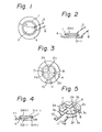
- this type of a microphone is such that a thin metal positive (+) electrode 2 is provided on the front side of a ceramic plate 1 and a thin metal negative (-) electrode 3 on the rear side thereof, the positive electrode 2 is connected to a conductor 5, and the negative electrode 3 is attached to a metal diaphragm 4 in an electrically conductive manner and is connected to a conductor 6 through the diaphragm 4.
- the value of a capacitor formed between the electrodes 2 and 3, each of which is commonly used and has a diameter of 20 - 25 m/m may reach the order of tens of thousands of picofarads.
- the output of the microphone is connected to an FET (field effect transistor) circuit through the conductors 5 and.6 and is amplified thereby, and, as the value of the capacitor for connecting it to the FET circuit without sacrificing the S/N ratio, the frequency characteristic and the sensitivity, the order of tens of picofarads may be sufficient.
- FET field effect transistor
- the capacitance between electrodes represents the order of tens of thousands of picofarads, the electrical energy was hardly utilized.
- the present invention has been accomplished by noticing that, by providing n-divided electrodes (where n is an integral number more than 2) on a ceramic plate in place of each of a pair of conventional electrodes as shown in Figs. 1 and 2, polarizing the respective n-divided electrodes in an alternating opposite-polarity pattern so that each of a pair of the electrodes faced across the ceramic plate forms a capacitor, and serially connecting the opposite-polarity electrodes of each of the capacitors each other, an input voltage to an FET amplifying circuit becomes n times.
- fan-shaped polarized electrodes 2a, 2b, 2c and 2d- are provided on the front side of a ceramic plate 1 and fan-shaped polarized electrodes 3a, 3b, 3c and 3d on the rear side thereof; the electrodes 2a and 2b are connected by a conductor 7, the electrodes 2c and 2d by a conductor 8 and the electrodes 3b and 3c by a conductor 9; and terminals 10 and 11 are connected to the electrodes 3a and 3d, respectively.
- the ceramic plate 1 with the electrodes, the conductors and the terminals on the opposite sides thereof is attached to a diaphragm 4 made by synthetic resin.
- An aluminum plate, in place of the diaphragm 4, which is electrically insulated by alumilite treatment, may be utilized and conductors as the terminals also may be directly soldered thereto.
- the value of the capacitor formed by, for example, 2a and 3a is and, therefore, the value of a system in which each of the capacitors is connected in series is .
- the ceramic microphone is constructed so that the n-divided electrodes, in place of the single conventional electrode, are provided on the ceramic plate. Accordingly, the following effects can be accomplished; .
Landscapes
- Physics & Mathematics (AREA)
- Engineering & Computer Science (AREA)
- Acoustics & Sound (AREA)
- Signal Processing (AREA)
- Electrostatic, Electromagnetic, Magneto- Strictive, And Variable-Resistance Transducers (AREA)
- Piezo-Electric Transducers For Audible Bands (AREA)
- Circuit For Audible Band Transducer (AREA)
- Details Of Audible-Bandwidth Transducers (AREA)
- Diaphragms For Electromechanical Transducers (AREA)
Applications Claiming Priority (2)
| Application Number | Priority Date | Filing Date | Title |
|---|---|---|---|
| JP1982152078U JPS5957100U (ja) | 1982-10-08 | 1982-10-08 | セラミツクマイクロホン |
| JP152078/82U | 1982-10-08 |
Publications (2)
| Publication Number | Publication Date |
|---|---|
| EP0106631A1 true EP0106631A1 (fr) | 1984-04-25 |
| EP0106631B1 EP0106631B1 (fr) | 1987-09-23 |
Family
ID=15532567
Family Applications (1)
| Application Number | Title | Priority Date | Filing Date |
|---|---|---|---|
| EP83306040A Expired EP0106631B1 (fr) | 1982-10-08 | 1983-10-05 | Microphone à céramique |
Country Status (5)
| Country | Link |
|---|---|
| US (1) | US4559418A (fr) |
| EP (1) | EP0106631B1 (fr) |
| JP (1) | JPS5957100U (fr) |
| CA (1) | CA1212451A (fr) |
| DE (1) | DE3373859D1 (fr) |
Families Citing this family (7)
| Publication number | Priority date | Publication date | Assignee | Title |
|---|---|---|---|---|
| US4691363A (en) * | 1985-12-11 | 1987-09-01 | American Telephone & Telegraph Company, At&T Information Systems Inc. | Transducer device |
| DK155269C (da) * | 1986-07-17 | 1989-07-24 | Brueel & Kjaer As | Trykgradientmikrofon |
| JPH07121630B2 (ja) * | 1987-05-30 | 1995-12-25 | 株式会社東芝 | Icカ−ド |
| JP2002534933A (ja) * | 1999-01-07 | 2002-10-15 | サーノフ コーポレイション | プリント回路基板を有する大型ダイアフラムマイクロフォン素子を備えた補聴器 |
| US7003127B1 (en) | 1999-01-07 | 2006-02-21 | Sarnoff Corporation | Hearing aid with large diaphragm microphone element including a printed circuit board |
| DE60128418T2 (de) * | 2000-03-16 | 2008-01-17 | Makita Corp., Anjo | Angetriebenes Schlagwerkzeug mit Mitteln zum Ermitteln des Schlaggeräusches |
| EP2397972B1 (fr) * | 2010-06-08 | 2015-01-07 | Vodafone Holding GmbH | Carte à puce avec microphone |
Citations (3)
| Publication number | Priority date | Publication date | Assignee | Title |
|---|---|---|---|---|
| US2863076A (en) * | 1947-02-07 | 1958-12-02 | Sonotone Corp | Dielectrostrictive signal and energy transducers |
| US2967957A (en) * | 1957-09-17 | 1961-01-10 | Massa Frank | Electroacoustic transducer |
| US3564303A (en) * | 1968-10-07 | 1971-02-16 | Westinghouse Electric Corp | Encapsulated transducer assembly |
Family Cites Families (9)
| Publication number | Priority date | Publication date | Assignee | Title |
|---|---|---|---|---|
| FR1354754A (fr) * | 1958-11-14 | 1964-03-13 | Transducteur bidirectionnel | |
| US3158762A (en) * | 1962-12-27 | 1964-11-24 | John J Horan | Bilaminar transducers |
| JPS4998196A (fr) * | 1973-01-19 | 1974-09-17 | ||
| GB1515287A (en) * | 1974-05-30 | 1978-06-21 | Plessey Co Ltd | Piezoelectric transducers |
| NL7502452A (en) * | 1975-03-03 | 1976-09-07 | Philips Nv | Piezo electric reversible transducer - eg a multiple sector series connected microphone membrane |
| SU607297A1 (ru) * | 1976-12-30 | 1978-05-15 | Предприятие П/Я Г-4097 | Устройство обработки сигналов на акустических поверхностных волнах |
| US4376302A (en) * | 1978-04-13 | 1983-03-08 | The United States Of America As Represented By The Secretary Of The Navy | Piezoelectric polymer hydrophone |
| US4268912A (en) * | 1978-06-06 | 1981-05-19 | Magnavox Government And Industrial Electronics Co. | Directional hydrophone suitable for flush mounting |
| US4424419A (en) * | 1981-10-19 | 1984-01-03 | Northern Telecom Limited | Electret microphone shield |
-
1982
- 1982-10-08 JP JP1982152078U patent/JPS5957100U/ja active Pending
-
1983
- 1983-10-04 CA CA000438277A patent/CA1212451A/fr not_active Expired
- 1983-10-05 EP EP83306040A patent/EP0106631B1/fr not_active Expired
- 1983-10-05 DE DE8383306040T patent/DE3373859D1/de not_active Expired
- 1983-10-05 US US06/539,316 patent/US4559418A/en not_active Expired - Lifetime
Patent Citations (3)
| Publication number | Priority date | Publication date | Assignee | Title |
|---|---|---|---|---|
| US2863076A (en) * | 1947-02-07 | 1958-12-02 | Sonotone Corp | Dielectrostrictive signal and energy transducers |
| US2967957A (en) * | 1957-09-17 | 1961-01-10 | Massa Frank | Electroacoustic transducer |
| US3564303A (en) * | 1968-10-07 | 1971-02-16 | Westinghouse Electric Corp | Encapsulated transducer assembly |
Also Published As
| Publication number | Publication date |
|---|---|
| JPS5957100U (ja) | 1984-04-13 |
| DE3373859D1 (en) | 1987-10-29 |
| CA1212451A (fr) | 1986-10-07 |
| EP0106631B1 (fr) | 1987-09-23 |
| US4559418A (en) | 1985-12-17 |
Similar Documents
| Publication | Publication Date | Title |
|---|---|---|
| US3439128A (en) | Miniature ceramic microphone | |
| US3736436A (en) | Electret pressure transducer | |
| US4329547A (en) | Dual section electret microphone | |
| US5298828A (en) | Ultrasonic electroacoustic transducer | |
| US3778561A (en) | Electret microphone | |
| US4559418A (en) | Ceramic microphone | |
| US4139842A (en) | Audible alarm unit | |
| US7099488B2 (en) | Planar speaker wiring layout | |
| JPH09187099A (ja) | 圧電フィルム素子 | |
| US3609416A (en) | Microacoustic surface-wave transducer | |
| US3562429A (en) | Sound transmitter with feedback and polarization circuitry | |
| EP0258912B1 (fr) | Un dispositif pour convertir un signal électrique en un signal acoustique comprenant un transducteur electrostatique | |
| SU805918A1 (ru) | Преобразователь поверхностных акустических волн | |
| WO1999037123A1 (fr) | Transducteurs piezo-electriques numeriques et procedes | |
| GB1276196A (en) | Electro-acoustic transducer | |
| KR840001425A (ko) | 분극된 고체유전 캐패시터 전자-음향 변환기 | |
| US4345118A (en) | Quartz tuning fork electro-acoustic transducer | |
| US4361735A (en) | Electret microphone circuit | |
| JP3331893B2 (ja) | 圧電共振子およびそれを用いたフィルタおよびam受信回路 | |
| US2878451A (en) | Piezolelectric resonator | |
| CN215573338U (zh) | 一种具有pvdf膜的传感器 | |
| JPS62200A (ja) | 圧電型マイクロホン | |
| JPS626400B2 (fr) | ||
| JPS59180599U (ja) | 圧電発音装置 | |
| RU2034412C1 (ru) | Электростатический акустический преобразователь |
Legal Events
| Date | Code | Title | Description |
|---|---|---|---|
| PUAI | Public reference made under article 153(3) epc to a published international application that has entered the european phase |
Free format text: ORIGINAL CODE: 0009012 |
|
| AK | Designated contracting states |
Designated state(s): DE GB |
|
| 17P | Request for examination filed |
Effective date: 19841015 |
|
| GRAA | (expected) grant |
Free format text: ORIGINAL CODE: 0009210 |
|
| AK | Designated contracting states |
Kind code of ref document: B1 Designated state(s): DE GB |
|
| REF | Corresponds to: |
Ref document number: 3373859 Country of ref document: DE Date of ref document: 19871029 |
|
| PLBE | No opposition filed within time limit |
Free format text: ORIGINAL CODE: 0009261 |
|
| STAA | Information on the status of an ep patent application or granted ep patent |
Free format text: STATUS: NO OPPOSITION FILED WITHIN TIME LIMIT |
|
| 26N | No opposition filed | ||
| PGFP | Annual fee paid to national office [announced via postgrant information from national office to epo] |
Ref country code: GB Payment date: 20000919 Year of fee payment: 18 |
|
| PGFP | Annual fee paid to national office [announced via postgrant information from national office to epo] |
Ref country code: DE Payment date: 20001222 Year of fee payment: 18 |
|
| PG25 | Lapsed in a contracting state [announced via postgrant information from national office to epo] |
Ref country code: GB Free format text: LAPSE BECAUSE OF NON-PAYMENT OF DUE FEES Effective date: 20011005 |
|
| REG | Reference to a national code |
Ref country code: GB Ref legal event code: IF02 |
|
| GBPC | Gb: european patent ceased through non-payment of renewal fee |
Effective date: 20011005 |
|
| PG25 | Lapsed in a contracting state [announced via postgrant information from national office to epo] |
Ref country code: DE Free format text: LAPSE BECAUSE OF NON-PAYMENT OF DUE FEES Effective date: 20020702 |