EP0106659A2 - Sekundäre Düsenstruktur für eine Gasturbinenbrennkammer - Google Patents
Sekundäre Düsenstruktur für eine Gasturbinenbrennkammer Download PDFInfo
- Publication number
- EP0106659A2 EP0106659A2 EP83306168A EP83306168A EP0106659A2 EP 0106659 A2 EP0106659 A2 EP 0106659A2 EP 83306168 A EP83306168 A EP 83306168A EP 83306168 A EP83306168 A EP 83306168A EP 0106659 A2 EP0106659 A2 EP 0106659A2
- Authority
- EP
- European Patent Office
- Prior art keywords
- fuel
- combustor
- air
- mixing
- zone
- Prior art date
- Legal status (The legal status is an assumption and is not a legal conclusion. Google has not performed a legal analysis and makes no representation as to the accuracy of the status listed.)
- Withdrawn
Links
Images



Classifications
-
- F—MECHANICAL ENGINEERING; LIGHTING; HEATING; WEAPONS; BLASTING
- F02—COMBUSTION ENGINES; HOT-GAS OR COMBUSTION-PRODUCT ENGINE PLANTS
- F02C—GAS-TURBINE PLANTS; AIR INTAKES FOR JET-PROPULSION PLANTS; CONTROLLING FUEL SUPPLY IN AIR-BREATHING JET-PROPULSION PLANTS
- F02C9/00—Controlling gas-turbine plants; Controlling fuel supply in air- breathing jet-propulsion plants
- F02C9/26—Control of fuel supply
-
- F—MECHANICAL ENGINEERING; LIGHTING; HEATING; WEAPONS; BLASTING
- F23—COMBUSTION APPARATUS; COMBUSTION PROCESSES
- F23R—GENERATING COMBUSTION PRODUCTS OF HIGH PRESSURE OR HIGH VELOCITY, e.g. GAS-TURBINE COMBUSTION CHAMBERS
- F23R3/00—Continuous combustion chambers using liquid or gaseous fuel
- F23R3/40—Continuous combustion chambers using liquid or gaseous fuel characterised by the use of catalytic means
-
- F—MECHANICAL ENGINEERING; LIGHTING; HEATING; WEAPONS; BLASTING
- F23—COMBUSTION APPARATUS; COMBUSTION PROCESSES
- F23R—GENERATING COMBUSTION PRODUCTS OF HIGH PRESSURE OR HIGH VELOCITY, e.g. GAS-TURBINE COMBUSTION CHAMBERS
- F23R3/00—Continuous combustion chambers using liquid or gaseous fuel
- F23R3/02—Continuous combustion chambers using liquid or gaseous fuel characterised by the air-flow or gas-flow configuration
- F23R3/04—Air inlet arrangements
-
- F—MECHANICAL ENGINEERING; LIGHTING; HEATING; WEAPONS; BLASTING
- F23—COMBUSTION APPARATUS; COMBUSTION PROCESSES
- F23R—GENERATING COMBUSTION PRODUCTS OF HIGH PRESSURE OR HIGH VELOCITY, e.g. GAS-TURBINE COMBUSTION CHAMBERS
- F23R3/00—Continuous combustion chambers using liquid or gaseous fuel
- F23R3/28—Continuous combustion chambers using liquid or gaseous fuel characterised by the fuel supply
- F23R3/34—Feeding into different combustion zones
- F23R3/346—Feeding into different combustion zones for staged combustion
Definitions
- the present invention generally relates to combustors employed in land based combustion turbines and more particularly to combustors in which substantially uniform mixing of fuel and air across the combustor mixing zone is needed prior to entry of the mix into the combustion zone, i.e. the catalyst zone in catalytic combustors.
- Premixing of fuel and air in premix combustors is needed to provide long combustor life, high combustor efficiency and low emissions through proper combustion operating temperatures and chemistry.
- Catalytic combustors provide a practical commercial solution offering low pollutant (and especially low NOx) combustion turbine operation for electric power plants and other land based applications; proper catalytic combustion especially requires substantial uniformity in the premixing of fuel and air within the combustor mixing zone.
- a catalytic combustor may be provided with a generally tubular envelope having a primary combustion zone followed in sequence first by a secondary fuel injection and mixing zone and finally by a catalyst.
- the primary combustion zone operates for example during startup when operating temperatures do not adequately support catalytic combustion.
- secondary fuel is injected into the mixing zone where it mixes with air for delivery to the flow channels through the catalyst.
- the secondary fuel injectors are disposed circumferentially about the mixing zone and they may inject fuel radially inwardly at right angles or otherwise into the combustor mixing zone.
- the fuel must be essentially completely vaporized before entering the catalyst zone which requires that the fuel nozzle produce very small droplets which can evaporate rapidly. Small droplets can be obtained by using a very high fuel nozzle pressure drop (pressure atomization), by using a small amount of high energy atomizing air (air assist), or by using a relatively large amount of low energy atomizing air (air blast). In all cases, the momentum of the resulting fuel. spray is quite high.
- the momentum of the fuel spray with respect to the momentum of the cross flowing air inside the combustor is high enough that the fuel tends to penetrate to the center (axis) of the combustor.
- This action produces a fuel rich core, i.e. the fuel/air ratio profile has a single center peak shape across a reference diameter of a cross section of the combustor mixing zone.
- the fuel/air ratio is highest at the axis in the fuel injection plane or region, and it decreases in the radial outward direction. As the mix flows downstream through the mixing zone, additional mixing action causes the fuel/air ratio profile to flatten somewhat. In general, however, the scope of fuel penetration in the injection region has resulted in too much axial fuel concentration to permit available downstream mixing to produce a substantially uniform fuel/air ratio distribution at the catalyst entry plane.
- the invention in its broad form comprises a generally tubular sidewall enclosing a downstream mixing zone where a mixture of fuel and air is developed for downstream combustion, said sidewall further enclosing an upstream primary zone into which primary air is admitted through sidewall openings to develop an axial airflow for mixing with downstream injected fuel, means for spraying secondary fuel in small rapidly evaporable droplets generally in the radial inward direction at a location between said primary zone and said mixing zone for mixing with the primary air flow, said secondary fuel spraying means including a plurality of nozzles disposed at an angle directed substantially downstream to enhance the mixing of fuel and air for improved uniformity of the fuel/air mixture at the mixing zone outlet.
- the structure includes fuel injector nozzles which are angled to inject fuel sprays at an angle toward the downstream direction, and swirlers which centrifuge and stir the fuel sprays into a wider spread to promote mixing. Accordingly, a more uniform fuel/air ratio profile is produced at the catalyst entry plane.
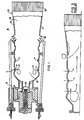
- a catalytic combustor 10 is shown in Figure 1 for a land based combustion turbine which is typically used in electric power and other industrial plants.
- the combustor 10 includes a generally tubular sidewall 12 having successive circumferential rows of holes 14, 16 for entry of air used in the combustion process.
- a primary fuel nozzle 20 admits fuel for burning in a primary zone 22 to generate the energy needed for startup until operating conditions support catalytic combustion.
- the primary nozzle 20 supplies some fuel for primary combustion during catalytic operation to provide any preheating needed to keep the gas temperature at a catalyst entry plane 24 at the value needed (i.e. approximately 1800 - 1950°F) for efficient catalytic combustion.
- the overall combustor operation involves amounts of primary fuel combustion such that NOx production is well below prescribed environmental limits.
- An outlet end 26 of the combustor wall 12 is outwardly flared and coupled to a conventional catalyst element 28 having a honeycomb structure.
- the catalyst outlet 30 is coupled to a transition duct (not shown) which directs the hot gases to the turbine (not shown).
- Secondary fuel is injected into the combustor 10 during the catalytic combustion phase of operation by a set of circumferentially spaced injectors 32 at the downstream end of the primary combustor zone 22. Air may or may not enter the combustor 10 at the injector locations.
- a combustor region 34 between the primary zone and the catalyst element 28 provides for mixing of the secondary fuel and air prior to its entry into the catalyst 28. The region 34 is referred to as a mixing zone, and combustion does not occur in this zone since flashback can damage the combustor and/or catalyst 28.
- the fuel/air distribution is controlled.and the center peaked fuel/air mix is avoided by the way in which the secondary fuel injector is structured and the manner in which it is disposed relative to the combustor wall.
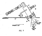
- each secondary fuel injector 32 includes a nozzle 37 ( Figure 7) angled toward the downstream direction as indicated by the reference character 33 ( Figure 7) to effect directly a greater axial velocity component for the fuel spray and reduced fuel penetration toward the combustor axis.
- the injector angle is set according to combustor geometry and operating conditions to shift the radius at which fuel peaking occurs so that a more uniform fuel/air mixture is produced across the entry face 24 of the catalyst element 28.
- a continuous air atomizing nozzle may be employed for the nozzle 37, as shown, for very fine droplet atomization, or a simple pressure-atomizing nozzle may be used. Among others, a natural gas injector may also be used.
- an axial swirler 35 and directive shroud 39 are mounted concentrically about each secondary nozzle 37 to provide additional air with a strong swirl component in intimate contact with the injected fuel spray.
- the fuel in the spray is acted upon by the stirring action of the air to provide increased fuel/air mixing.
- the centrifuging action of the air causes the fuel spray to spread more greatly thereby further enhancing the fuel/air mixing.
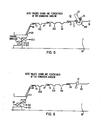
- Figure 3 shows the angled nozzle 37 and swirler 35 with dimension information and scoop and nozzle location information for a combustor having a shell and front end similar to those of the combustor of Figure 1.
- Figure 4 shows a like arrangement for a fuel injector 32 without a swirler. Approximately 10.6% of the combustor air may pass through the six combined secondary fuel nozzle swirlers (Figure 5).
- Figure 5 provides percentage airflow information for the Figure 3 combination and Figure 5 provides percentage airflow information for the Figure 4 combustor.
- a combustor 40 is provided with an annular four nozzle primary fuel supply 42 and a secondary fuel injector assembly 44 supplied by an axial atomizing air and fuel supply line 46 and located at the end of the primary zone and the front end of the fuel mixing zone.
- the injector assembly includes a fuel manifold 48 which supplies six fuel nozzles 50 equally disposed about the combustor space at a suitably radial location.
- the nozles 50 are angled toward the downstream direction and the outer wall of the combustor.
- An axial nozzle 52 is included to spray fuel directly along the combustor axis.
- the fuel spray from each nozzles is directed by an air jet.
- Radial cross-flow struts 54 supply air to an air manifold 56 for the air jets and for cooling air for the secondary fuel assembly liner. Atomizing air for the secondary nozzles is supplied by the line 46.
- Appropriate cooling structure such as a film or transpiration cooling arrangement, is provided for the secondary injection liner and the air struts.
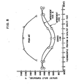
- the catalyst outlet temperature which reflects the catalyst entry fuel/air ratio profile, shows improved evenness of distribution (i.e. a generally flattened shape) for embodiments of the invention as compared to the center peaked distribution for the prior art.
- Figure 2 shows the configuration used for the prior art in the test while Figure 1 shows the invention configuration used in the test.
- Case I employed angled fuel nozzles and Case II includes angled fuel nozzles and axial swirlers. The provision of angled nozzles and/or swirlers in the invention configuration is the principal reason for the improvements observed.
Landscapes
- Engineering & Computer Science (AREA)
- Chemical & Material Sciences (AREA)
- Combustion & Propulsion (AREA)
- Mechanical Engineering (AREA)
- General Engineering & Computer Science (AREA)
- Chemical Kinetics & Catalysis (AREA)
Applications Claiming Priority (2)
| Application Number | Priority Date | Filing Date | Title |
|---|---|---|---|
| US43467582A | 1982-10-15 | 1982-10-15 | |
| US434675 | 1982-10-15 |
Publications (2)
| Publication Number | Publication Date |
|---|---|
| EP0106659A2 true EP0106659A2 (de) | 1984-04-25 |
| EP0106659A3 EP0106659A3 (de) | 1984-05-30 |
Family
ID=23725206
Family Applications (1)
| Application Number | Title | Priority Date | Filing Date |
|---|---|---|---|
| EP83306168A Withdrawn EP0106659A3 (de) | 1982-10-15 | 1983-10-12 | Sekundäre Düsenstruktur für eine Gasturbinenbrennkammer |
Country Status (6)
| Country | Link |
|---|---|
| EP (1) | EP0106659A3 (de) |
| JP (1) | JPS5989927A (de) |
| KR (1) | KR840007139A (de) |
| AR (1) | AR232041A1 (de) |
| CA (1) | CA1209810A (de) |
| IL (1) | IL69919A0 (de) |
Cited By (3)
| Publication number | Priority date | Publication date | Assignee | Title |
|---|---|---|---|---|
| US6223537B1 (en) * | 1997-11-24 | 2001-05-01 | Alliedsignal Power Systems | Catalytic combustor for gas turbines |
| US7874157B2 (en) | 2008-06-05 | 2011-01-25 | General Electric Company | Coanda pilot nozzle for low emission combustors |
| US8176739B2 (en) | 2008-07-17 | 2012-05-15 | General Electric Company | Coanda injection system for axially staged low emission combustors |
Families Citing this family (1)
| Publication number | Priority date | Publication date | Assignee | Title |
|---|---|---|---|---|
| JPS6139268U (ja) * | 1984-08-06 | 1986-03-12 | 三菱重工業株式会社 | ガスタ−ビン用燃焼器 |
Family Cites Families (6)
| Publication number | Priority date | Publication date | Assignee | Title |
|---|---|---|---|---|
| US3919840A (en) * | 1973-04-18 | 1975-11-18 | United Technologies Corp | Combustion chamber for dissimilar fluids in swirling flow relationship |
| IT1063699B (it) * | 1975-09-16 | 1985-02-11 | Westinghouse Electric Corp | Metodo di avviamento di una turbina a gas di grande potenza con un combustore catalitico |
| US4118171A (en) * | 1976-12-22 | 1978-10-03 | Engelhard Minerals & Chemicals Corporation | Method for effecting sustained combustion of carbonaceous fuel |
| GB2098720B (en) * | 1979-01-12 | 1983-04-27 | Gen Electric | Stationary gas turbine combustor arrangements |
| GB2073400B (en) * | 1980-04-02 | 1984-03-14 | United Technologies Corp | Fuel injector |
| IN155658B (de) * | 1981-03-05 | 1985-02-16 | Westinghouse Electric Corp |
-
1983
- 1983-10-03 CA CA000438217A patent/CA1209810A/en not_active Expired
- 1983-10-06 IL IL69919A patent/IL69919A0/xx unknown
- 1983-10-07 AR AR294482A patent/AR232041A1/es active
- 1983-10-12 EP EP83306168A patent/EP0106659A3/de not_active Withdrawn
- 1983-10-14 JP JP58191084A patent/JPS5989927A/ja active Granted
- 1983-10-15 KR KR1019830004890A patent/KR840007139A/ko not_active Ceased
Cited By (3)
| Publication number | Priority date | Publication date | Assignee | Title |
|---|---|---|---|---|
| US6223537B1 (en) * | 1997-11-24 | 2001-05-01 | Alliedsignal Power Systems | Catalytic combustor for gas turbines |
| US7874157B2 (en) | 2008-06-05 | 2011-01-25 | General Electric Company | Coanda pilot nozzle for low emission combustors |
| US8176739B2 (en) | 2008-07-17 | 2012-05-15 | General Electric Company | Coanda injection system for axially staged low emission combustors |
Also Published As
| Publication number | Publication date |
|---|---|
| AR232041A1 (es) | 1985-04-30 |
| KR840007139A (ko) | 1984-12-05 |
| EP0106659A3 (de) | 1984-05-30 |
| JPS622649B2 (de) | 1987-01-21 |
| IL69919A0 (en) | 1984-01-31 |
| JPS5989927A (ja) | 1984-05-24 |
| CA1209810A (en) | 1986-08-19 |
Similar Documents
| Publication | Publication Date | Title |
|---|---|---|
| US7266945B2 (en) | Fuel injection apparatus | |
| US7926282B2 (en) | Pure air blast fuel injector | |
| CN1467407B (zh) | 带有截留涡流空腔的气体涡轮发动机燃烧室筒 | |
| EP0500256B1 (de) | Luft-/Kraftstoff-Mischer für eine Gasturbinenbrennkammer | |
| US7878000B2 (en) | Pilot fuel injector for mixer assembly of a high pressure gas turbine engine | |
| US5930999A (en) | Fuel injector and multi-swirler carburetor assembly | |
| US4265615A (en) | Fuel injection system for low emission burners | |
| US6272840B1 (en) | Piloted airblast lean direct fuel injector | |
| US6675587B2 (en) | Counter swirl annular combustor | |
| US5596873A (en) | Gas turbine combustor with a plurality of circumferentially spaced pre-mixers | |
| US9328924B2 (en) | Combustion system | |
| US6571559B1 (en) | Anti-carboning fuel-air mixer for a gas turbine engine combustor | |
| EP1413830A2 (de) | Druckluftinjektor für Kraftstoff mit verbessertem Luftverteiler und Pilot | |
| JPH07217451A (ja) | 燃料噴射装置 | |
| WO2015165735A1 (en) | Combustor burner arrangement | |
| JP2008128631A (ja) | 空気と燃料の混合物を噴射する装置と、このような装置を備える燃焼チャンバ及びターボ機械 | |
| CN113154449B (zh) | 一种油气高效混合的低污染燃烧室 | |
| EP0106659A2 (de) | Sekundäre Düsenstruktur für eine Gasturbinenbrennkammer | |
| EP0103159B1 (de) | Brennkammer für eine Turbine mit gleichmässigerer Durchmischung von Brennstoff und Luft für verbesserte stromabwärtige Verbrennung | |
| EP4094019B1 (de) | Zerstäuber für gasturbinentriebwerk |
Legal Events
| Date | Code | Title | Description |
|---|---|---|---|
| PUAI | Public reference made under article 153(3) epc to a published international application that has entered the european phase |
Free format text: ORIGINAL CODE: 0009012 |
|
| PUAL | Search report despatched |
Free format text: ORIGINAL CODE: 0009013 |
|
| AK | Designated contracting states |
Designated state(s): BE CH DE FR GB IT LI NL SE |
|
| AK | Designated contracting states |
Designated state(s): BE CH DE FR GB IT LI NL SE |
|
| 17P | Request for examination filed |
Effective date: 19841129 |
|
| STAA | Information on the status of an ep patent application or granted ep patent |
Free format text: STATUS: THE APPLICATION IS DEEMED TO BE WITHDRAWN |
|
| 18D | Application deemed to be withdrawn |
Effective date: 19861002 |
|
| RIN1 | Information on inventor provided before grant (corrected) |
Inventor name: PILLSBURY, PAUL WALTER Inventor name: SCHEIHING, PAUL EDWARD |