EP0106694A1 - Flexibler Transmissionsriemen und Riemantrieb - Google Patents
Flexibler Transmissionsriemen und Riemantrieb Download PDFInfo
- Publication number
- EP0106694A1 EP0106694A1 EP83306300A EP83306300A EP0106694A1 EP 0106694 A1 EP0106694 A1 EP 0106694A1 EP 83306300 A EP83306300 A EP 83306300A EP 83306300 A EP83306300 A EP 83306300A EP 0106694 A1 EP0106694 A1 EP 0106694A1
- Authority
- EP
- European Patent Office
- Prior art keywords
- belt
- pulley
- tooth
- power transmission
- line
- Prior art date
- Legal status (The legal status is an assumption and is not a legal conclusion. Google has not performed a legal analysis and makes no representation as to the accuracy of the status listed.)
- Granted
Links
- 230000005540 biological transmission Effects 0.000 title claims abstract description 53
- 238000005304 joining Methods 0.000 claims description 6
- 230000002093 peripheral effect Effects 0.000 claims description 3
- 230000001747 exhibiting effect Effects 0.000 abstract description 2
- 238000010276 construction Methods 0.000 description 5
- 230000013011 mating Effects 0.000 description 4
- 230000009467 reduction Effects 0.000 description 3
- 230000007704 transition Effects 0.000 description 3
- VQKWAUROYFTROF-UHFFFAOYSA-N arc-31 Chemical compound O=C1N(CCN(C)C)C2=C3C=C4OCOC4=CC3=NN=C2C2=C1C=C(OC)C(OC)=C2 VQKWAUROYFTROF-UHFFFAOYSA-N 0.000 description 2
- 230000008901 benefit Effects 0.000 description 2
- 230000007246 mechanism Effects 0.000 description 2
- 238000000034 method Methods 0.000 description 2
- 238000012986 modification Methods 0.000 description 2
- 230000004048 modification Effects 0.000 description 2
- 238000009958 sewing Methods 0.000 description 2
- 230000006835 compression Effects 0.000 description 1
- 238000007906 compression Methods 0.000 description 1
- 230000003247 decreasing effect Effects 0.000 description 1
- 238000006073 displacement reaction Methods 0.000 description 1
- 238000004519 manufacturing process Methods 0.000 description 1
- 238000005259 measurement Methods 0.000 description 1
- 230000004044 response Effects 0.000 description 1
- 238000005096 rolling process Methods 0.000 description 1
- 238000005728 strengthening Methods 0.000 description 1
Images


Classifications
-
- F—MECHANICAL ENGINEERING; LIGHTING; HEATING; WEAPONS; BLASTING
- F16—ENGINEERING ELEMENTS AND UNITS; GENERAL MEASURES FOR PRODUCING AND MAINTAINING EFFECTIVE FUNCTIONING OF MACHINES OR INSTALLATIONS; THERMAL INSULATION IN GENERAL
- F16H—GEARING
- F16H7/00—Gearings for conveying rotary motion by endless flexible members
- F16H7/02—Gearings for conveying rotary motion by endless flexible members with belts; with V-belts
-
- F—MECHANICAL ENGINEERING; LIGHTING; HEATING; WEAPONS; BLASTING
- F16—ENGINEERING ELEMENTS AND UNITS; GENERAL MEASURES FOR PRODUCING AND MAINTAINING EFFECTIVE FUNCTIONING OF MACHINES OR INSTALLATIONS; THERMAL INSULATION IN GENERAL
- F16G—BELTS, CABLES, OR ROPES, PREDOMINANTLY USED FOR DRIVING PURPOSES; CHAINS; FITTINGS PREDOMINANTLY USED THEREFOR
- F16G1/00—Driving-belts
- F16G1/28—Driving-belts with a contact surface of special shape, e.g. toothed
-
- F—MECHANICAL ENGINEERING; LIGHTING; HEATING; WEAPONS; BLASTING
- F16—ENGINEERING ELEMENTS AND UNITS; GENERAL MEASURES FOR PRODUCING AND MAINTAINING EFFECTIVE FUNCTIONING OF MACHINES OR INSTALLATIONS; THERMAL INSULATION IN GENERAL
- F16H—GEARING
- F16H7/00—Gearings for conveying rotary motion by endless flexible members
- F16H7/02—Gearings for conveying rotary motion by endless flexible members with belts; with V-belts
- F16H7/023—Gearings for conveying rotary motion by endless flexible members with belts; with V-belts with belts having a toothed contact surface or regularly spaced bosses or hollows for slipless or nearly slipless meshing with complementary profiled contact surface of a pulley
Definitions
- This invention relates to power transmission systems utilizing toothed power transmission belts cooperating with toothed pulleys, and also relates to belts and pulleys for use in such a system.
- the conjugate form of the belt tooth is that tooth form described on the pulley which corresponds to the volume between the belt and the pulley which is not swept out by the belt tooth as the belt moves into contact with the pulley.
- Use of conjugate teeth on the pulley is desirable as it insures that the belt and pulley teeth are able to engage and disengage without interference.
- the Hoback patent U.S. Pat. No. 4,037,485, discloses a power transmission system which, when the belt thereof is put under sufficient tension the material of the individual belt teeth spreads within the pulley cavities so as to substantially fill those cavities and thereby substantially reduce backlash.
- a construction has been found not to be practical since the high tension required and the resulting interference between the belt teeth and pulley cavities, when meshing, result in accelerated wear of the belt jacket material so as to substantially reduce the operational life thereof.
- the high tension which is required by Hoback results in a loss of useful power and necessitates a strengthening and overdesigning of the structural components of the system. All of these disadvantages are mitigated by the system according to the present inventio.
- the principal object of the invention is therefore to provide a power transmission system that is practical for high-speed, high-torque applications while exhibiting sufficiently low-backlash so as to be suitable for precise positioning and/or indexing mechanisms yet having the minimum clearance between belt teeth .and pulley teeth which is required to prevent entry or exit meshing interference between the two.
- a flexible power transmission belt having a plurality of teeth separated from each other by a plurality of belt land areas alternating with the teeth, each tooth having a center line and comprising a pair of opposed flanks each of which in longitudinal cross-section has a generally convex arcuate contour, each flank being joined to the adjacent belt land area by a root having an arcuate contour approximating an arc of a circle having a given first radius, and having a tooth tip portion connecting said pair of flanks at a location spaced from said root, each tooth having a longitudinal width dimension measured between the points where said root arcs intersect the opposing flanks of the belt tooth and a height dimension measured from the belt land line (i.e.
- each of the arcuate flanks approximating an arc of a circle and being formed such that a line drawn tangent thereto at a point spaced from the belt land line, by a distance equal to 0.3 times the said width dimension will intersect the tooth center line at an angle in the range of from 18° to 23°.
- a power transmission system comprising a belt as aforesaid in combination with a pulley having grooves which are substantially the conjugate of the belt teeth, or with a pulley having a plurality of identical peripheral belt-engaging teeth defining between them pulley cavities wherein each pulley cavity possesses substantially identical fore and aft flank surfaces, at least part of each said flank surface being shaped in cross-section as a curve approximating the arc of a circle and said pulley teeth having pulley land surfaces at the tips thereof, said land surfaces defining in longitudinal cross-section portion of a pulley land line approximating a circle concentric with the center of the pulley, and said pulley cavity having a cavity bottom portion connecting the opposite arcuate flanks thereof at points on said flanks furthest spaced from said pulley land line, each said pulley tooth tip having arcuate portions adjacent the pulley land line and joining the respective arcuate flank portions to the adjacent pulley
- an endless belt 10 engages driving and driven pulleys 11 and 12.
- U.S. Patent No. 2,507,852 to Case and U.S. Patent 3,756,091 to Miller may be consulted for a more detailed description of this general class of toothed belt and pulley system and the construction thereof.
- the entire contents of the Case and Miller patents are hereby incorporated herein by reference.
- the belt 10 may be made in any one of a number of ways, but it is preferable to use the method described in U.S. Patent No. 3,078,206 to Skura, the entire contents of which are also incorporated herein by reference.
- An alternative method for manufacture of the belt is described in the aforesaid Case Patent.
- Each tooth 13 is of substantially U-shaped longitudinal cross-section symmetrical with respect to a tooth center line X-X.
- Each tooth 13 has a pair of symmetrical opposed flank portions formed by curved lines 21 and 22, respectively, each approximating to an arc of a circle and forming a tooth with substantially identical fore and aft portions.
- the arc 21 is drawn from center 23 on the belt land line L, is of a radius Rl and extends from point A to point B.
- the belt land line L is the line connecting line segments 32 of length I which represent, in longitudinal cross-section, the surface of the belt at the land regions thereof, i.e. between adjacent belt teeth 13.
- the arc 22 is drawn from center 24, is of radius R2 and extends from point C to point D.
- the centers 23 and 24 are displaced from each other and lie on the belt land line L on opposite sides of the radial center line X-X of the belt tooth 13.
- the center 23 and the arc 21, drawn from that center lie on opposite sides of the center line X-X and similarly, the center 24 and arc 22 drawn from that center, lie on opposite sides of the center line X-X.
- the radii Rl and R2 are equal and their respective centers 23,24 lie at equal distances from the center line X-X.
- each belt tooth is preferably formed by two further curved lines 25 and 26, each being an arc of a circle, and connected by a line segment 27 having end points E and F.
- the arc 25 is drawn from a center 28, has a radius R3 and extends from point D to point E.
- the arc 26 is drawn from center 29, has a radius R4 and joins points B and F.
- the centers 28 and 29 are displaced one from another, lie at equal distances at opposite sides of the tooth center line X-X and lie on a line which is parallel to the belt land line.
- the radii R3 and R4 are equal.
- the line segment 27 is flat and has an outermost surface portion located a distance H from the belt land line L. The distance H represents the height of the belt tooth.
- Teeth 13 as seen in the sectional view of Fig. 2 are constructed so that the outermost portions thereof have a longitudinal cross-sectional configuration which is constant across the transverse cross-section of the belt and which is substantially composed of the arcs 21 and 22 forming the flanks, the arcs 25 and 26 together with line segment 27 forming the tip and the arcs 30 and 31 forming the roots thereof.
- the arcs 30 and 31 of adjacent teeth 13 are connected by a line segment 32, having end points I and G, which represents the longitudinal length of the land area between adjacent teeth and also defines the belt land line L.
- the arc 30 is drawn from a center 33, is of radius R5 and extends from point A to point G.
- the arc 31 is drawn from a center 34, is of radius R6 and extends from point I to point C.
- Line segment 32 connects point I of one belt tooth 13 to point G of an adjacent belt tooth 13.
- Each tooth 13 has a longitudinal width W measured between the points A and C where the root arcs 30 and 31 intersect the respective flank arc 21 and 22.
- the convex curves of the belt tooth flanks 21, 22 have a length (measured along their curved contour) in longitudinal cross-section, which is equal to at least 40% of the height H of the belt tooth and which for the Fig. 4 embodiment is preferably equal to about 50% of the height H and for the Fig 2 embodiment is preferably equal to about 70% of the height H of the belt tooth.
- the tooth height H is determined such that the height H to width W ratio is within a first predetermined range, namely, between 0.50 and 0.67, with the preferred height H being equal to 0.60 of the width W.
- the curvature of the arcuate flanks 21, 22 of the belt tooth 13 is chosen such that when a line T is drawn tangentially to the corresponding flank, e.g. to arcuate flank 21 at the point J representing the point along such flank at which such arcuate flank is intersected by a line L 3 parallel to the belt land line L and spaced therefrom a distance equal to 0.3W (i.e. 0.3 times the width W), the pressure angle ⁇ formed between the tangent line T and the tooth center line X-X is within a second predetermined range, namely, between 18 degrees and 23 degrees, with the preferred pressure angle being 21.5 degrees.
- the radii R5 and R6 for the arcs defining the tooth roots 30 and 31 are centered on a line L 4 which is parallel to the belt land line L and spaced therefrom a distance which is less than the 0.3W distance of the L 3 line.
- the pressure angle measurement as defined herein is taken at a location on the working surface of the flank of the belt tooth.
- the arcuate flank 21 therefore begins at point A and extends through point J (which is at the distance 0.3W from the belt line L measured along vertical axis X-X and at which point tangent line T to the curve 21 makes an angle with the center line X-X) to point B (which lies at a vertical distance from the belt land line L equal to the height H less an amount equal to or less than the length of radius R4).
- Arcuate flank 22 is formed in identical manner to the flank 21 described above and extends from point C through point K to point D.
- the belt tooth flanks 21 and 22 are the arcs of circles of radii Rl and R2 respectively, it is necessary only that they approximate closely such arcs but need not precisely describe such arcs.
- the curved flanks can (in cross-sectional contour) be generated by the involute of a circle (not shown) of diameter Q, the center of which is located on the side of the belt land line which is opposite to the side on which the tooth is located.
- a diameter Q for a belt having the dimensions stated above for the belt of Example "A", is 15.25 mm (0.6") centered 7.625 mm (0.3") from the belt and line and spaced 0.127 mm (0.005") from the center line X-X of the belt tooth on the same side thereof as the curved flank which it describes.
- flanks can be shaped such that in cross-section their contour can be a portion of a parabola, hyperbola, or ellipse, all of which would result in curves 21, 22 which closely approximate the arc of a circle having a radius Rl or R2.
- the preferred length of radiis Rl and R2 is approximately 0.85 times the tooth width dimension (W).
- the pressure angle OCof the belt tooth is 21.5 degrees
- the length (1) of line 32 is equal to 0.2 times the belt tooth width (W)
- the length of tooth tip line 27 is 0.36 times the belt tooth width (W) or 0.36W
- the tooth height H is 0.6 4W
- the tip of belt tooth 13 is formed by identical non-intersecting arcs 25 and 26 of radii equal to 0.19 times the belt tooth width (W) and joined together by a straight tooth tip line 27.
- the centers 28 and 29 of tooth tip arcs 25 and 26 are located equidistant on opposite sides of tooth center line X-X along a line parallel to the belt land line (L) and spaced therefrom a distance equal to H minus the length of radius R3.
- R3 being equal to R4.
- the distance of the centers 28 and 29 of tooth tip radii R3 and R4, respectively, from center line X-X, is chosen such that a smooth transition will result between the arcs 25, 26 and the arcuate flanks 21, 22 on the one hand and the line 27, on the other hand.
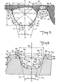
- Fig. 3 shows a typical profile of a pulley tooth and cavity according to the invention.
- the profile of the tooth and cavity is made up as follows.
- Each cavity 13p is of substantially U-shaped longitudinal cross-section and is formed by two non-intersecting curved lines, 21p, 22p, a cavity bottom portion 27p, a pair of cavity bottom curved lines 25p and 26p and a pair of curved cavity top lines 30p and 31p.
- Cavity flank line 21p is drawn from a center 23p, is of radius Rlp and extends from point Ap to point B .
- the flank arc 22p is drawn from center 24p, is of radius R2p and extends from point Cp to point Dp.
- the centers 23p and 24p are displaced from each other and lie on opposite sides of the radial center line X-X of the pulley groove.
- the center 23p and the arc 21p drawn from that center lie on the opposite sides of the center line X-X, and similarly, the center 24p and arc 22p drawn from that center lie on the opposite sides of the center line X-X.
- the radii Rlp and R2p are equal, and the centers 23p and 24p lie at equal radial distances from the center of the pulley and preferably lie on or closely adjacent to the pulley land line Lp which is the circle representing the outermost circumference of the pulley and which includes the pulley land areas, represented in longitudinal cross-section by the line segment 32p of length lp in Fig. 3.
- the centers 23p and 24p furthermore, lie at equal distances to opposite sides of the center line X-X.
- Each pulley tooth tip is formed by two non-intersecting curved lines 30p and 31p each approximating to an arc of a circle, connected by the line segment 32p.
- the arc 30p is drawn from center 33p, has a radius R5p and extends from point Ap to point Gp.
- the arc 31p is drawn from center 34p has a radius R6p and joins points Ip and Cp.
- the centers 33p and 34p are displaced from one another on a circle concentric with the circle representing the pulley land line Lp and having a radius equal to the outer circumference of the pulley less the length of radius R5p.
- the centers 33p and 34p of a pulley tooth tip are spaced apart a distance lp equal to the length of the pulley tooth land segment represented in longitudinal cross-section by the arcuate line 32p.
- the radii R5p. and R6p are equal.
- the line segment 32p is part of an arc of a circle having a radius drawn from the center of the pulley and forming the pulley land line Lp.
- the arc 21p defining one flank of the pulley cavity and the arc 30p defining part of the adjacent pulley tooth tip are joined, i.e. intersect, at point A .
- the arc 22p defining the other flank of the pulley cavity is joined to (i.e. intersects) the arc 31p of the adjacent pulley tooth tip at point C .
- the profile from point Ip to point Ip in Fig. 3, is repeated around the circumference of the pulley to define the other teeth and cavities.
- the line segment 27p joins points Ep and Fp to form the base of the pulley cavity.
- a pair of arcs 26p and 25p connect the points Ep and Fp to the points Dp and Bp, respectively.
- the arc 25p is drawn from center 28p, is of radius R3p and extends from point Dp to point Ep.
- the arc 26p is drawn from center 29p, is of radius R4p and extends from point Bp to point Fp.
- the centers 28p and 29p are displaced from each other and lie at equal distances to opposite sides of the radial center line X-X of the pulley cavity 13p.
- the center 28p and the arc 25p drawn from that center lie to the same side of the center line X-X, and similarly, the center 29p and the arc 26p drawn from that center lie on the same side of the center line X-X.
- the radii R3p and R4p are equal and the centers 28p and 29p lie at equal distances from the center of the pulley and thus also at equal distances from the base 27p of the cavity 13p.
- the radii of the curves 25p, 26p, 30p and 31p, as well as the locations of their centers of curvature are chosen such that smooth transitions are provided between the curve 21p and land segment 32p, on the one hand, and between curve 21p and pulley cavity bottom 27p, on the other hand.
- the curves 25p and 31p are chosen such as to provide smooth transitions between the curved flank 22p and the pulley tip land 32p, on the one hand, and between the curved flank 22p and the pulley cavity bottom segment 27p on the other hand.
- flank segment 21p defining one wall of the pulley cavity is such that ' it closely approximates a portion of a circle having a radius Rlp and passes through point Jp as it extends from point Ap to point Bp.
- Point Ap is the point at which root arc 30p intersects the convex arcuate flank 21p.
- point Cp is the point at which the root arc 31p intersects convex arcuate flank 22p.
- Points Ap and Cp are located on a circle L4p which is concentric with the center of the pulley. It is between points Ap and Cp at which the pulley width Wp is measured.
- a second circle L 3p concentric with the pulley and having a radius equal to the maximum pulley radius (i.e. the radius of a circle represented by Lp) minus an amount equal to 0.3Wp, intersects the arcs 21p and 22p at points Jp and Kp, respectively.
- the curvature of arcuate flanks 21p and 22p is such that lines drawn tangent to the flanks 21p, 22p at points Jp and Kp, respectively, form with the center line X-X of the pulley cavity 13p an angle p.
- the mating pulley cavity should have a flank pressure angle ⁇ p measured at a distance of 0.3Wp from the pulley land line Lp of between 18.5 and 23.5 degrees with a depth H p of between 0.47 and 0.64 of the cavity width W p and a ratio of pulley cavity flank radius of curvature R1 p R2 p to cavity width W p between 0.67 and 0.87.
- the preferred pulley cavity for belt example "A" above would have the following dimensions:
- the power transmission system according to the present invention exhibits approximately 69% less clearance (c) between the belt tooth flank and the pulley groove flank as measured along the 0.3W'p line than is exhibited by a power transmission system designed in accordance with the teachings of the Miller patent.
- the foregoing comparison figures are the result of comparing graphic layouts of the power transmission systems designed in accordance with the present invention and those of the Miller design. Since in Fig. 6 the system is in no load condition the clearance (c) is equal to the aggregate clearances shown as (kc) and (kc) on opposite sides of the belt tooth 13.
- the belt tooth flank arc 21 is tangent to the tooth root arc 30 at a point A which lies on a line connecting the center point 23 of radius R1 and the center point 33 of radius R5.
- the point C on the other side of tooth 13 represents the point at which arc 22 meets and is tangent to, the tooth root arc 31 and is a point on the line connecting the centers 24 and 34 of arcs 22 and 31 respectively.
- the same relationship exists with respect to the location of centers 33p and 34p in Fig. 3 and for the corresponding belt tooth root and pulley tooth tip centers in Figs. 4 and 5.
- FIG. 4 and 5 Another preferred embodiment of the invention is shown in Figs. 4 and 5.
- the belt and pulley in Figs. -4 and 5 are identical in all respects with the belt and pulley, shown in Figs. 2 and 3, except that instead of the flat belt tooth tip line 27 and the flat pulley cavity bottom portion 27p in Figs. 2 and 3, the Figs. 4 and 5 embodiments have a convex arcuate belt tooth tip portion 37' and a concave arcuate pulley cavity bottom portion 37'p respectively.
- the tooth tip portion comprises a convex curvilinear portion which is a continuation of the generally convex arcuate flanks, being joined thereto by the arcs 25', 26'. Other ways of effecting this continuation may be used.
- the radius R7' _of the belt tooth tip portion 37' of Fig. 4 has its center (not shown) located along an extension of the belt tooth center line X'-X'.
- the tooth height H' is the distance between the belt land line L' and the point of intersection of the convex curve 37' with the tooth center line X'-X'.
- the reference numbers in Figs. 4 and 5 are the same as the reference numerals in Figs. 2 and 3 for substantially identical parts except that in Figs. 4 and 5 each reference numeral is followed with a prime (') designation.
- the pulley cavity of Fig. 5 has, with respect to the body of the pulley, a concave bottom 37p' formed by a radius R7p' having its center (not shown) on the cavity center line X'-X'.
- the various radii forming the pulley cavities of Figs. 3 and 5, it will be seen, are chosen so as to be conjugate to the belt teeth of Figs. 2 and 4, respectively.
- the belt teeth 1 3' preferably have a height H' equal to 0.63W', a pressure angle ⁇ ' equal to 21.5 degrees, a land segment 32' between the root portion of adjacent teeth 13' having a length equal to 0.49W', flank radii R1' and R2' equal to 0.85W' and having their centers 23', 24' located on the belt land line L', tooth tip radii R3' and R4' equal to 0.19W' and a convex tooth tip surface line 37', joining the arcs 25' and 26' and formed by a radius R7' having its center on the intersection of the belt land line with center line X'-X' and having a length equal to 0.63W'.
- Fig. 6 of the drawings the belt and pulley are shown in meshed, but in no-load, condition.
- Fig. 6 represents a belt according to the Fig. 4 embodiment of the present invention "wrapped around", but not torque loaded, with respect to, a pulley according to Fig. 5.
- the belt tooth tip is in "touch" contact with the bottom of the pulley cavity and the pulley tooth tip is in "touch” contact with the belt land area.
- the lag is calculated to be approximately 0.9° while with pulleys and belt according to the new design of this invention the lag would be reduced to approximately 0.3°.
- the reduction in lag i.e. backlash
- the reduction in lag would result in a substantial reduction in table overtravel and therefore -the response to system command would be substantially improved.
Landscapes
- Engineering & Computer Science (AREA)
- General Engineering & Computer Science (AREA)
- Mechanical Engineering (AREA)
- Devices For Conveying Motion By Means Of Endless Flexible Members (AREA)
- Pulleys (AREA)
- Two-Way Televisions, Distribution Of Moving Picture Or The Like (AREA)
- Transplanting Machines (AREA)
- Input Circuits Of Receivers And Coupling Of Receivers And Audio Equipment (AREA)
- Radio Relay Systems (AREA)
- Gear Transmission (AREA)
- Transmission Devices (AREA)
- Retarders (AREA)
- General Details Of Gearings (AREA)
Priority Applications (1)
| Application Number | Priority Date | Filing Date | Title |
|---|---|---|---|
| AT83306300T ATE24587T1 (de) | 1982-10-20 | 1983-10-18 | Flexibler transmissionsriemen und riemantrieb. |
Applications Claiming Priority (2)
| Application Number | Priority Date | Filing Date | Title |
|---|---|---|---|
| US06/435,435 US4515577A (en) | 1982-10-20 | 1982-10-20 | Low backlash-high-torque power transmission system and toothed belt used therein |
| US435435 | 1982-10-20 |
Publications (2)
| Publication Number | Publication Date |
|---|---|
| EP0106694A1 true EP0106694A1 (de) | 1984-04-25 |
| EP0106694B1 EP0106694B1 (de) | 1986-12-30 |
Family
ID=23728378
Family Applications (1)
| Application Number | Title | Priority Date | Filing Date |
|---|---|---|---|
| EP83306300A Expired EP0106694B1 (de) | 1982-10-20 | 1983-10-18 | Flexibler Transmissionsriemen und Riemantrieb |
Country Status (11)
| Country | Link |
|---|---|
| US (1) | US4515577A (de) |
| EP (1) | EP0106694B1 (de) |
| JP (2) | JPS5989852A (de) |
| KR (1) | KR900001355B1 (de) |
| AT (1) | ATE24587T1 (de) |
| AU (1) | AU572799B2 (de) |
| CA (1) | CA1211959A (de) |
| DE (1) | DE3368741D1 (de) |
| ES (2) | ES8503804A1 (de) |
| IN (1) | IN160352B (de) |
| MX (1) | MX161227A (de) |
Cited By (20)
| Publication number | Priority date | Publication date | Assignee | Title |
|---|---|---|---|---|
| GB2159602A (en) * | 1984-06-11 | 1985-12-04 | Pirelli Transmissioni Ind Spa | Toothed pulley and transmission containing the same |
| EP0203235A1 (de) * | 1985-04-22 | 1986-12-03 | The Gates Rubber Company | Zahnriemen und Zahnrad |
| EP0255333A1 (de) * | 1986-07-28 | 1988-02-03 | Honda Giken Kogyo Kabushiki Kaisha | Zahnriemen |
| EP0316197A1 (de) * | 1987-11-12 | 1989-05-17 | Mitsuboshi Belting Ltd. | Zahntreibriemen und Antrieb |
| EP0327873A1 (de) * | 1988-01-27 | 1989-08-16 | Bando Chemical Industries, Limited | Zahnriemen und einen solchen aufweisendes Getriebe |
| EP0368099A1 (de) * | 1988-11-11 | 1990-05-16 | PIRELLI TRASMISSIONI INDUSTRIALI S.p.A. | Zahntreibriemen und entsprechender Antrieb |
| EP0384049A1 (de) * | 1989-02-20 | 1990-08-29 | Mitsuboshi Belting Ltd. | Treibriemen und Treibantrieb |
| EP0371311A3 (de) * | 1988-11-29 | 1991-08-14 | DAYCO PTI S.p.A. | Zahnriemenscheibe und zugehörige Getriebeeinrichtung |
| EP0505919A2 (de) | 1991-03-26 | 1992-09-30 | Continental Aktiengesellschaft | Zahnriementrieb |
| WO2000058644A1 (en) * | 1999-03-25 | 2000-10-05 | Bando Chemical Industries, Ltd. | Toothed belt, toothed belt transmission device, and office appliances |
| AT407075B (de) * | 1984-11-15 | 2000-12-27 | Dayco Products Inc | Kombination aus einer zahnriemenscheibe und einem zahnriemen |
| WO2009134313A3 (en) * | 2008-05-02 | 2010-03-18 | The Gates Corporation | Synchronous belt sprocket |
| EP2217830A4 (de) * | 2007-12-14 | 2011-03-02 | Gates Corp | Gürtel |
| EP2787243A1 (de) * | 2013-03-05 | 2014-10-08 | ContiTech Antriebssysteme GmbH | Keilrippenriemen |
| WO2017092895A1 (de) * | 2015-11-30 | 2017-06-08 | Contitech Antriebssysteme Gmbh | Zahnriementrieb |
| WO2017144140A1 (de) * | 2016-02-22 | 2017-08-31 | Contitech Antriebssysteme Gmbh | Zahnriementrieb |
| WO2018164939A1 (en) * | 2017-03-07 | 2018-09-13 | Gates Corporation | Toothed belt and sprocket system |
| US10989293B2 (en) | 2016-06-09 | 2021-04-27 | Contitech Antriebssysteme Gmbh | Non-metal sprocket and bushing apparatus |
| US11015694B2 (en) | 2016-06-09 | 2021-05-25 | Contitech Antriebssysteme Gmbh | Bushing and hub to prevent back-rotation |
| US11585423B2 (en) | 2020-10-03 | 2023-02-21 | Contitech Antriebssysteme Gmbh | Composite sprocket |
Families Citing this family (31)
| Publication number | Priority date | Publication date | Assignee | Title |
|---|---|---|---|---|
| JPS6064354U (ja) * | 1983-10-12 | 1985-05-07 | 三ツ星ベルト株式会社 | 歯付ベルトの駆動装置 |
| JPS6065460U (ja) * | 1983-10-13 | 1985-05-09 | 三ツ星ベルト株式会社 | 歯付ベルトの駆動装置 |
| JPS6474341A (en) * | 1987-09-14 | 1989-03-20 | Mitsuboshi Belting Ltd | Driving device of toothed belt |
| JPH0221046A (ja) * | 1987-12-29 | 1990-01-24 | Mitsuboshi Belting Ltd | 歯付ベルト及びこれを用いた駆動装置 |
| USRE34485E (en) * | 1987-11-12 | 1993-12-21 | Mitsuboshi Belting, Ltd. | Power transmission toothed belt and drive |
| JPH071051B2 (ja) * | 1988-01-13 | 1995-01-11 | 三ツ星ベルト株式会社 | 歯付ベルト及びこれを用いた駆動装置 |
| JPH03217389A (ja) * | 1990-01-20 | 1991-09-25 | Shimano Ind Co Ltd | 自転車用多段スプロケットホイール |
| JP3117094B2 (ja) * | 1991-11-18 | 2000-12-11 | 日本フィリップス株式会社 | 乾式ひげそり器 |
| US5797306A (en) * | 1995-05-01 | 1998-08-25 | Marathon Electric Mfg. Corp. | Lamination notching apparatus |
| US5807194A (en) | 1996-10-31 | 1998-09-15 | The Gates Corporation | Toothed belt |
| JP4460681B2 (ja) * | 1999-07-19 | 2010-05-12 | バンドー化学株式会社 | 歯付ベルト伝動システム |
| JP2003532851A (ja) * | 2000-05-09 | 2003-11-05 | ザ ゲイツ コーポレイション | ブロック型cvtベルト |
| JP2002098201A (ja) * | 2000-09-25 | 2002-04-05 | Bando Chem Ind Ltd | 歯付ベルト伝動装置及び事務用機器 |
| JP2002098202A (ja) * | 2000-09-25 | 2002-04-05 | Bando Chem Ind Ltd | 歯付ベルト伝動装置及び事務用機器 |
| ES2306757T3 (es) | 2001-01-12 | 2008-11-16 | The Gates Corporation | Correa de transmision de potencia de baja elongacion. |
| ITTO20010557A1 (it) * | 2001-06-08 | 2002-12-08 | Dayco Europe Srl | Conghia dentata. |
| US7125356B2 (en) * | 2001-11-06 | 2006-10-24 | Borgwarner Inc. | Tension-reducing random sprocket |
| CN100396967C (zh) * | 2001-11-27 | 2008-06-25 | 利滕斯汽车公司 | 具有非圆形驱动部件的同步传动装置及其运转和构造方法 |
| US8932165B2 (en) | 2006-03-31 | 2015-01-13 | The Gates Corporation | Toothed power transmission belt |
| WO2008156483A1 (en) * | 2007-06-20 | 2008-12-24 | Borgwarner Inc. | Resonance tension reducing sprocket with combined radial variation and sprocket wrap |
| CN101918735B (zh) * | 2007-09-28 | 2014-11-26 | 博格华纳公司 | 链条与链轮系统中的多个减少张力的链轮 |
| EP2372186B1 (de) * | 2009-06-23 | 2015-04-01 | Zhejiang Kingland Transmission Industry Co., Ltd. | Zusammengesetztes keilriemengetriebesystem mit kombination aus reibungsgetriebe und klauengetriebe |
| WO2014063228A1 (en) | 2012-10-22 | 2014-05-01 | Litens Automotive Partnership | Tensioner with increased damping |
| CN105518340B (zh) | 2013-09-11 | 2018-02-16 | 利滕斯汽车合伙公司 | 阻尼增强且具有位于基部杯状件构型上的臂的张紧器 |
| CN114028666B (zh) | 2015-03-31 | 2025-10-28 | 费雪派克医疗保健有限公司 | 用于将气体供应至气道的用户接口和系统 |
| US10859141B2 (en) | 2015-10-28 | 2020-12-08 | Litens Automotive Partnership | Tensioner with first and second damping members and increased damping |
| US10907721B2 (en) * | 2015-12-09 | 2021-02-02 | Borgwarner Inc. | Non-prevalent order random sprocket |
| KR102776008B1 (ko) | 2016-08-11 | 2025-03-10 | 피셔 앤 페이켈 핼스케어 리미티드 | 압궤 가능 도관, 환자 인터페이스 및 헤드기어 연결부 |
| JP6829388B2 (ja) * | 2017-02-27 | 2021-02-10 | 株式会社椿本チエイン | 歯付ベルト伝動装置 |
| US10687468B1 (en) * | 2018-12-18 | 2020-06-23 | Contitech Antriebssysteme Gmbh | Flexible synchronous toothed belt with narrow splice |
| WO2023214990A1 (en) * | 2022-05-06 | 2023-11-09 | The Gates Corporation | Optimizing belt and wheel systems |
Citations (9)
| Publication number | Priority date | Publication date | Assignee | Title |
|---|---|---|---|---|
| US2507852A (en) * | 1945-12-12 | 1950-05-16 | Us Rubber Co | Transmission belt and drive |
| US2937538A (en) * | 1958-05-09 | 1960-05-24 | Us Rubber Co | Belt and gear drive |
| US3078206A (en) * | 1959-02-25 | 1963-02-19 | Us Rubber Co | Method of forming belt teeth in reinforced positive drive belts |
| US3756091A (en) * | 1970-02-19 | 1973-09-04 | Uniroyal Inc | Positive power transmission system |
| FR2238094A1 (de) * | 1973-07-20 | 1975-02-14 | Goodyear Tire & Rubber | |
| FR2412762A1 (fr) * | 1977-12-23 | 1979-07-20 | Uniroyal Inc | Poulie perfectionnee pour systemes d'entrainement positif |
| GB2084688A (en) * | 1980-09-03 | 1982-04-15 | Mitsubishi Motors Corp | Toothed belt power transmission device |
| US4337056A (en) * | 1977-12-12 | 1982-06-29 | Uniroyal, Inc. | Mechanical power transmission system |
| GB2109503A (en) * | 1981-11-12 | 1983-06-02 | Mitsuboshi Belting Ltd | Toothed belt |
Family Cites Families (13)
| Publication number | Priority date | Publication date | Assignee | Title |
|---|---|---|---|---|
| AU451700B2 (en) * | 1971-01-20 | 1974-07-31 | Uniroyal Inc | Positive power transmission system |
| US3969946A (en) * | 1974-07-03 | 1976-07-20 | The Goodyear Tire & Rubber Company | Circular side positive drive belt teeth |
| US3977265A (en) * | 1975-06-02 | 1976-08-31 | The Gates Rubber Company | Positive drive belt system |
| US4041789A (en) * | 1975-12-18 | 1977-08-16 | The Goodyear Tire & Rubber Company | Belt drive including toothed belts and toothed pulleys of improved tooth configurations |
| ZA786820B (en) * | 1977-12-14 | 1979-11-28 | Uniroyal Inc | Mechanical power transmission system |
| US4403979A (en) * | 1977-12-23 | 1983-09-13 | Uniroyal, Inc. | Pulley for positive drive systems |
| JPS56167955A (en) * | 1980-05-27 | 1981-12-23 | Mitsuboshi Belting Ltd | Transmission apparatus with toothed belt |
| JPS571714A (en) * | 1980-06-04 | 1982-01-06 | Mitsubishi Chem Ind Ltd | Heater |
| JPS5728812A (en) * | 1980-07-29 | 1982-02-16 | Toshiba Corp | Steam flow rate controlling valve |
| JPS5744866A (en) * | 1980-08-29 | 1982-03-13 | Fujitsu Ltd | High-temperature testing device for semiconductor device |
| DE3034185C2 (de) * | 1980-09-11 | 1982-09-16 | Ford-Werke AG, 5000 Köln | Steuerungsantrieb für Brennkraftmaschinen |
| JPS5760501A (en) * | 1980-09-29 | 1982-04-12 | Heishiro Tanami | Recording method for plural recording modes |
| US4452594A (en) * | 1980-10-10 | 1984-06-05 | The Gates Rubber Company | Toothed belt and sprocket |
-
1982
- 1982-10-20 US US06/435,435 patent/US4515577A/en not_active Expired - Lifetime
-
1983
- 1983-09-27 IN IN667/DEL/83A patent/IN160352B/en unknown
- 1983-09-29 CA CA000438036A patent/CA1211959A/en not_active Expired
- 1983-09-30 AU AU19803/83A patent/AU572799B2/en not_active Expired
- 1983-10-18 EP EP83306300A patent/EP0106694B1/de not_active Expired
- 1983-10-18 DE DE8383306300T patent/DE3368741D1/de not_active Expired
- 1983-10-18 AT AT83306300T patent/ATE24587T1/de not_active IP Right Cessation
- 1983-10-19 KR KR1019830004941A patent/KR900001355B1/ko not_active Expired
- 1983-10-19 MX MX199148A patent/MX161227A/es unknown
- 1983-10-19 ES ES526571A patent/ES8503804A1/es not_active Expired
- 1983-10-20 JP JP58195379A patent/JPS5989852A/ja active Granted
-
1984
- 1984-10-31 ES ES537284A patent/ES8601432A1/es not_active Expired
-
1987
- 1987-07-09 JP JP62169905A patent/JPS6347536A/ja active Granted
Patent Citations (9)
| Publication number | Priority date | Publication date | Assignee | Title |
|---|---|---|---|---|
| US2507852A (en) * | 1945-12-12 | 1950-05-16 | Us Rubber Co | Transmission belt and drive |
| US2937538A (en) * | 1958-05-09 | 1960-05-24 | Us Rubber Co | Belt and gear drive |
| US3078206A (en) * | 1959-02-25 | 1963-02-19 | Us Rubber Co | Method of forming belt teeth in reinforced positive drive belts |
| US3756091A (en) * | 1970-02-19 | 1973-09-04 | Uniroyal Inc | Positive power transmission system |
| FR2238094A1 (de) * | 1973-07-20 | 1975-02-14 | Goodyear Tire & Rubber | |
| US4337056A (en) * | 1977-12-12 | 1982-06-29 | Uniroyal, Inc. | Mechanical power transmission system |
| FR2412762A1 (fr) * | 1977-12-23 | 1979-07-20 | Uniroyal Inc | Poulie perfectionnee pour systemes d'entrainement positif |
| GB2084688A (en) * | 1980-09-03 | 1982-04-15 | Mitsubishi Motors Corp | Toothed belt power transmission device |
| GB2109503A (en) * | 1981-11-12 | 1983-06-02 | Mitsuboshi Belting Ltd | Toothed belt |
Cited By (32)
| Publication number | Priority date | Publication date | Assignee | Title |
|---|---|---|---|---|
| AT403951B (de) * | 1984-06-11 | 1998-07-27 | Dayco Pti Spa | Riemenscheibe für ein synchronantriebssystem |
| FR2565657A1 (fr) * | 1984-06-11 | 1985-12-13 | Pirelli Transmissioni Ind Spa | Poulie de transmission synchrone, destinee a cooperer avec une courroie crantee en matiere polymere, et transmission ainsi obtenue |
| US4696665A (en) * | 1984-06-11 | 1987-09-29 | Pirelli Transmissioni Industriali S.P.A. | Pulley for a synchronous drive system comprising a polymeric material toothed-belt and related transmission |
| AU585864B2 (en) * | 1984-06-11 | 1989-06-29 | Pirelli Trasmissioni Industriali S.P.A. | Pulley for a synchronous drive system comprising a polymeric material toothed-belt and relative transmission |
| GB2159602A (en) * | 1984-06-11 | 1985-12-04 | Pirelli Transmissioni Ind Spa | Toothed pulley and transmission containing the same |
| AT407075B (de) * | 1984-11-15 | 2000-12-27 | Dayco Products Inc | Kombination aus einer zahnriemenscheibe und einem zahnriemen |
| EP0203235A1 (de) * | 1985-04-22 | 1986-12-03 | The Gates Rubber Company | Zahnriemen und Zahnrad |
| EP0255333A1 (de) * | 1986-07-28 | 1988-02-03 | Honda Giken Kogyo Kabushiki Kaisha | Zahnriemen |
| US4840608A (en) * | 1986-07-28 | 1989-06-20 | Honda Giken Kogyo Kabushiki Kaisha | Toothed belt |
| EP0316197A1 (de) * | 1987-11-12 | 1989-05-17 | Mitsuboshi Belting Ltd. | Zahntreibriemen und Antrieb |
| EP0327873A1 (de) * | 1988-01-27 | 1989-08-16 | Bando Chemical Industries, Limited | Zahnriemen und einen solchen aufweisendes Getriebe |
| US5046993A (en) * | 1988-11-11 | 1991-09-10 | Pirelli Trasmissioni Industriali S.P.A. | Tooth belt and means of transmission related thereto |
| EP0368099A1 (de) * | 1988-11-11 | 1990-05-16 | PIRELLI TRASMISSIONI INDUSTRIALI S.p.A. | Zahntreibriemen und entsprechender Antrieb |
| EP0371311A3 (de) * | 1988-11-29 | 1991-08-14 | DAYCO PTI S.p.A. | Zahnriemenscheibe und zugehörige Getriebeeinrichtung |
| EP0384049A1 (de) * | 1989-02-20 | 1990-08-29 | Mitsuboshi Belting Ltd. | Treibriemen und Treibantrieb |
| EP0505919A2 (de) | 1991-03-26 | 1992-09-30 | Continental Aktiengesellschaft | Zahnriementrieb |
| EP0505919A3 (en) * | 1991-03-26 | 1992-12-16 | Continental Aktiengesellschaft | Toothed belt drive |
| WO2000058644A1 (en) * | 1999-03-25 | 2000-10-05 | Bando Chemical Industries, Ltd. | Toothed belt, toothed belt transmission device, and office appliances |
| US6485384B1 (en) | 1999-03-25 | 2002-11-26 | Bando Chemical Industries, Inc. | Toothed belt, toothed belt power transmission apparatus, and business equipment employing the same |
| EP2217830A4 (de) * | 2007-12-14 | 2011-03-02 | Gates Corp | Gürtel |
| WO2009134313A3 (en) * | 2008-05-02 | 2010-03-18 | The Gates Corporation | Synchronous belt sprocket |
| US8070634B2 (en) | 2008-05-02 | 2011-12-06 | The Gates Corporation | Synchronous belt sprocket |
| CN102016354B (zh) * | 2008-05-02 | 2013-11-27 | 盖茨公司 | 同步带链轮 |
| EP2787243A1 (de) * | 2013-03-05 | 2014-10-08 | ContiTech Antriebssysteme GmbH | Keilrippenriemen |
| WO2017092895A1 (de) * | 2015-11-30 | 2017-06-08 | Contitech Antriebssysteme Gmbh | Zahnriementrieb |
| CN108291626A (zh) * | 2015-11-30 | 2018-07-17 | 康蒂泰克驱动系统有限公司 | 齿形皮带传动装置 |
| CN108291626B (zh) * | 2015-11-30 | 2021-08-31 | 康蒂泰克驱动系统有限公司 | 齿形皮带传动装置 |
| WO2017144140A1 (de) * | 2016-02-22 | 2017-08-31 | Contitech Antriebssysteme Gmbh | Zahnriementrieb |
| US10989293B2 (en) | 2016-06-09 | 2021-04-27 | Contitech Antriebssysteme Gmbh | Non-metal sprocket and bushing apparatus |
| US11015694B2 (en) | 2016-06-09 | 2021-05-25 | Contitech Antriebssysteme Gmbh | Bushing and hub to prevent back-rotation |
| WO2018164939A1 (en) * | 2017-03-07 | 2018-09-13 | Gates Corporation | Toothed belt and sprocket system |
| US11585423B2 (en) | 2020-10-03 | 2023-02-21 | Contitech Antriebssysteme Gmbh | Composite sprocket |
Also Published As
| Publication number | Publication date |
|---|---|
| MX161227A (es) | 1990-08-23 |
| CA1211959A (en) | 1986-09-30 |
| ATE24587T1 (de) | 1987-01-15 |
| JPS5989852A (ja) | 1984-05-24 |
| JPS6347536A (ja) | 1988-02-29 |
| JPS6314215B2 (de) | 1988-03-30 |
| KR900001355B1 (ko) | 1990-03-08 |
| AU1980383A (en) | 1984-05-03 |
| KR840006514A (ko) | 1984-11-30 |
| IN160352B (de) | 1987-07-11 |
| ES537284A0 (es) | 1985-10-16 |
| DE3368741D1 (en) | 1987-02-05 |
| ES526571A0 (es) | 1985-03-01 |
| US4515577A (en) | 1985-05-07 |
| AU572799B2 (en) | 1988-05-19 |
| ES8503804A1 (es) | 1985-03-01 |
| ES8601432A1 (es) | 1985-10-16 |
| JPH0570735B2 (de) | 1993-10-05 |
| EP0106694B1 (de) | 1986-12-30 |
Similar Documents
| Publication | Publication Date | Title |
|---|---|---|
| EP0106694B1 (de) | Flexibler Transmissionsriemen und Riemantrieb | |
| US4337056A (en) | Mechanical power transmission system | |
| US4233852A (en) | Mechanical power transmission system | |
| US4403979A (en) | Pulley for positive drive systems | |
| EP0109202B1 (de) | Antriebskette | |
| KR970001193B1 (ko) | 톱니벨트 및 그 벨트를 사용한 동력전달장치 | |
| US4571224A (en) | Belt drive system | |
| US4899609A (en) | Gears having a tooth-profile with a smaller relative of curvature at a contact point | |
| US4427403A (en) | Toothed belt power transmission device | |
| US7993229B2 (en) | Power transmission chain and power transmission assembly using the same | |
| EP2279361B1 (de) | Synchrones zahnriemenrad | |
| JPS6137489B2 (de) | ||
| US3881364A (en) | Low noise gearing | |
| EP0371311B1 (de) | Zahnriemenscheibe und zugehörige Getriebeeinrichtung | |
| EP0316197B1 (de) | Zahntreibriemen und Antrieb | |
| EP0368099A1 (de) | Zahntreibriemen und entsprechender Antrieb | |
| EP0049962B1 (de) | Zahnriemen und Riemenscheibe | |
| JPH0550604B2 (de) | ||
| JPS635626B2 (de) | ||
| KR20070087590A (ko) | 볼록한 풀리 시브를 구비한 변속기용 구동 벨트 | |
| US4295837A (en) | Synchronous belt drive system | |
| US3969946A (en) | Circular side positive drive belt teeth | |
| EP0201562B1 (de) | Synchronantriebsystem | |
| JP5216975B2 (ja) | チェーンリンクプレート、このチェーンリンクプレートを含むチェーン、このチェーンにより形成されるチェーンドライブおよびこのチェーンドライブを装備する車両 | |
| JP2009510367A (ja) | チェーンリンクプレート、このチェーンリンクプレートを含むチェーン、このチェーンにより形成されるチェーンドライブおよびこのチェーンドライブを装備する車両 |
Legal Events
| Date | Code | Title | Description |
|---|---|---|---|
| PUAI | Public reference made under article 153(3) epc to a published international application that has entered the european phase |
Free format text: ORIGINAL CODE: 0009012 |
|
| AK | Designated contracting states |
Designated state(s): AT BE DE FR GB IT NL SE |
|
| 17P | Request for examination filed |
Effective date: 19841018 |
|
| GRAA | (expected) grant |
Free format text: ORIGINAL CODE: 0009210 |
|
| AK | Designated contracting states |
Kind code of ref document: B1 Designated state(s): AT BE DE FR GB IT NL SE |
|
| REF | Corresponds to: |
Ref document number: 24587 Country of ref document: AT Date of ref document: 19870115 Kind code of ref document: T |
|
| REF | Corresponds to: |
Ref document number: 3368741 Country of ref document: DE Date of ref document: 19870205 |
|
| ITF | It: translation for a ep patent filed | ||
| ET | Fr: translation filed | ||
| PLBE | No opposition filed within time limit |
Free format text: ORIGINAL CODE: 0009261 |
|
| STAA | Information on the status of an ep patent application or granted ep patent |
Free format text: STATUS: NO OPPOSITION FILED WITHIN TIME LIMIT |
|
| 26N | No opposition filed | ||
| ITPR | It: changes in ownership of a european patent |
Owner name: CESSIONE;THE GATES RUBBER COMPANY |
|
| REG | Reference to a national code |
Ref country code: GB Ref legal event code: 732 |
|
| NLS | Nl: assignments of ep-patents |
Owner name: THE GATES RUBBER COMPANY TE DENVER, COLORADO, VER. |
|
| REG | Reference to a national code |
Ref country code: FR Ref legal event code: TP Ref country code: FR Ref legal event code: CA |
|
| ITTA | It: last paid annual fee | ||
| EAL | Se: european patent in force in sweden |
Ref document number: 83306300.1 |
|
| REG | Reference to a national code |
Ref country code: GB Ref legal event code: IF02 |
|
| PGFP | Annual fee paid to national office [announced via postgrant information from national office to epo] |
Ref country code: FR Payment date: 20021002 Year of fee payment: 20 |
|
| PGFP | Annual fee paid to national office [announced via postgrant information from national office to epo] |
Ref country code: SE Payment date: 20021003 Year of fee payment: 20 Ref country code: AT Payment date: 20021003 Year of fee payment: 20 |
|
| PGFP | Annual fee paid to national office [announced via postgrant information from national office to epo] |
Ref country code: GB Payment date: 20021009 Year of fee payment: 20 |
|
| PGFP | Annual fee paid to national office [announced via postgrant information from national office to epo] |
Ref country code: NL Payment date: 20021011 Year of fee payment: 20 |
|
| PGFP | Annual fee paid to national office [announced via postgrant information from national office to epo] |
Ref country code: BE Payment date: 20021025 Year of fee payment: 20 |
|
| PGFP | Annual fee paid to national office [announced via postgrant information from national office to epo] |
Ref country code: DE Payment date: 20021031 Year of fee payment: 20 |
|
| PG25 | Lapsed in a contracting state [announced via postgrant information from national office to epo] |
Ref country code: GB Free format text: LAPSE BECAUSE OF EXPIRATION OF PROTECTION Effective date: 20031017 |
|
| PG25 | Lapsed in a contracting state [announced via postgrant information from national office to epo] |
Ref country code: NL Free format text: LAPSE BECAUSE OF EXPIRATION OF PROTECTION Effective date: 20031018 Ref country code: AT Free format text: LAPSE BECAUSE OF EXPIRATION OF PROTECTION Effective date: 20031018 |
|
| BE20 | Be: patent expired |
Owner name: THE *GATES RUBBER CY Effective date: 20031018 |
|
| REG | Reference to a national code |
Ref country code: GB Ref legal event code: PE20 |
|
| NLV7 | Nl: ceased due to reaching the maximum lifetime of a patent |
Effective date: 20031018 |
|
| EUG | Se: european patent has lapsed |