EP0106721A2 - System zur Beobachtung und automatische Mengenbestimmung von durch Fluoreszenz erfassbaren Ereignissen - Google Patents
System zur Beobachtung und automatische Mengenbestimmung von durch Fluoreszenz erfassbaren Ereignissen Download PDFInfo
- Publication number
- EP0106721A2 EP0106721A2 EP83401710A EP83401710A EP0106721A2 EP 0106721 A2 EP0106721 A2 EP 0106721A2 EP 83401710 A EP83401710 A EP 83401710A EP 83401710 A EP83401710 A EP 83401710A EP 0106721 A2 EP0106721 A2 EP 0106721A2
- Authority
- EP
- European Patent Office
- Prior art keywords
- signals
- tube
- localized area
- fluorescence
- shooting
- Prior art date
- Legal status (The legal status is an assumption and is not a legal conclusion. Google has not performed a legal analysis and makes no representation as to the accuracy of the status listed.)
- Withdrawn
Links
Images


Classifications
-
- G—PHYSICS
- G01—MEASURING; TESTING
- G01N—INVESTIGATING OR ANALYSING MATERIALS BY DETERMINING THEIR CHEMICAL OR PHYSICAL PROPERTIES
- G01N21/00—Investigating or analysing materials by the use of optical means, i.e. using sub-millimetre waves, infrared, visible or ultraviolet light
- G01N21/62—Systems in which the material investigated is excited whereby it emits light or causes a change in wavelength of the incident light
- G01N21/63—Systems in which the material investigated is excited whereby it emits light or causes a change in wavelength of the incident light optically excited
- G01N21/64—Fluorescence; Phosphorescence
- G01N21/645—Specially adapted constructive features of fluorimeters
- G01N21/6456—Spatial resolved fluorescence measurements; Imaging
-
- G—PHYSICS
- G01—MEASURING; TESTING
- G01J—MEASUREMENT OF INTENSITY, VELOCITY, SPECTRAL CONTENT, POLARISATION, PHASE OR PULSE CHARACTERISTICS OF INFRARED, VISIBLE OR ULTRAVIOLET LIGHT; COLORIMETRY; RADIATION PYROMETRY
- G01J1/00—Photometry, e.g. photographic exposure meter
- G01J1/42—Photometry, e.g. photographic exposure meter using electric radiation detectors
- G01J1/44—Electric circuits
- G01J2001/4446—Type of detector
- G01J2001/4493—Type of detector with image intensifyer tube [IIT]
-
- G—PHYSICS
- G01—MEASURING; TESTING
- G01N—INVESTIGATING OR ANALYSING MATERIALS BY DETERMINING THEIR CHEMICAL OR PHYSICAL PROPERTIES
- G01N15/00—Investigating characteristics of particles; Investigating permeability, pore-volume or surface-area of porous materials
- G01N15/10—Investigating individual particles
- G01N15/14—Optical investigation techniques, e.g. flow cytometry
- G01N15/1468—Optical investigation techniques, e.g. flow cytometry with spatial resolution of the texture or inner structure of the particle
-
- G—PHYSICS
- G01—MEASURING; TESTING
- G01N—INVESTIGATING OR ANALYSING MATERIALS BY DETERMINING THEIR CHEMICAL OR PHYSICAL PROPERTIES
- G01N21/00—Investigating or analysing materials by the use of optical means, i.e. using sub-millimetre waves, infrared, visible or ultraviolet light
- G01N21/62—Systems in which the material investigated is excited whereby it emits light or causes a change in wavelength of the incident light
- G01N21/63—Systems in which the material investigated is excited whereby it emits light or causes a change in wavelength of the incident light optically excited
- G01N21/64—Fluorescence; Phosphorescence
- G01N21/645—Specially adapted constructive features of fluorimeters
- G01N2021/6463—Optics
- G01N2021/6471—Special filters, filter wheel
-
- G—PHYSICS
- G01—MEASURING; TESTING
- G01N—INVESTIGATING OR ANALYSING MATERIALS BY DETERMINING THEIR CHEMICAL OR PHYSICAL PROPERTIES
- G01N21/00—Investigating or analysing materials by the use of optical means, i.e. using sub-millimetre waves, infrared, visible or ultraviolet light
- G01N21/62—Systems in which the material investigated is excited whereby it emits light or causes a change in wavelength of the incident light
- G01N21/63—Systems in which the material investigated is excited whereby it emits light or causes a change in wavelength of the incident light optically excited
- G01N21/64—Fluorescence; Phosphorescence
- G01N21/645—Specially adapted constructive features of fluorimeters
- G01N21/6456—Spatial resolved fluorescence measurements; Imaging
- G01N21/6458—Fluorescence microscopy
-
- G—PHYSICS
- G01—MEASURING; TESTING
- G01N—INVESTIGATING OR ANALYSING MATERIALS BY DETERMINING THEIR CHEMICAL OR PHYSICAL PROPERTIES
- G01N2201/00—Features of devices classified in G01N21/00
- G01N2201/10—Scanning
- G01N2201/102—Video camera
-
- Y—GENERAL TAGGING OF NEW TECHNOLOGICAL DEVELOPMENTS; GENERAL TAGGING OF CROSS-SECTIONAL TECHNOLOGIES SPANNING OVER SEVERAL SECTIONS OF THE IPC; TECHNICAL SUBJECTS COVERED BY FORMER USPC CROSS-REFERENCE ART COLLECTIONS [XRACs] AND DIGESTS
- Y10—TECHNICAL SUBJECTS COVERED BY FORMER USPC
- Y10S—TECHNICAL SUBJECTS COVERED BY FORMER USPC CROSS-REFERENCE ART COLLECTIONS [XRACs] AND DIGESTS
- Y10S436/00—Chemistry: analytical and immunological testing
- Y10S436/80—Fluorescent dyes, e.g. rhodamine
-
- Y—GENERAL TAGGING OF NEW TECHNOLOGICAL DEVELOPMENTS; GENERAL TAGGING OF CROSS-SECTIONAL TECHNOLOGIES SPANNING OVER SEVERAL SECTIONS OF THE IPC; TECHNICAL SUBJECTS COVERED BY FORMER USPC CROSS-REFERENCE ART COLLECTIONS [XRACs] AND DIGESTS
- Y10—TECHNICAL SUBJECTS COVERED BY FORMER USPC
- Y10S—TECHNICAL SUBJECTS COVERED BY FORMER USPC CROSS-REFERENCE ART COLLECTIONS [XRACs] AND DIGESTS
- Y10S436/00—Chemistry: analytical and immunological testing
- Y10S436/805—Optical property
Definitions
- the present invention relates to a system allowing the automatic observation and quantification of phenomena capable of being detected by an emission of fluorescence, this fluorescence possibly being either spontaneous or provoked.
- immunofluorescence that is to say to the study of the immunological reactions of living organisms by labeling products of a reaction with one or more fluorescent bodies rendering this reaction visible - and, for explanatory purposes, it will be more particularly described below in the context of this particular application, which should not be considered as limiting the scope of the present invention.
- fluorescence is the property of certain bodies to emit photons in response to the reception of visible or invisible radiation.
- resonance fluorescence because of the energy loss between absorption and emission of the radiation, the fluorescence photons are less energetic than the photons of the incident radiation and their wavelength is therefore bigger.
- the lifespan of this fluorescence is very short, of the order of a nanosecond, although variable depending on the nature and physical state of the excited molecules. Even in continuous irradiation, the phenomenon of fluorescence decreases exponentially as a function of time. In addition, the quantum yield of fluorescence is weak, for example equal to 3% for the fluorescence of chlorophyll, so that the intensity of the fluorescence, which however varies according to the intensity of the excitation source, the concentration, the pH, the presence of impurities and the nature of the excited molecules, is also low. It is therefore easy to see that, because of its transience and its continuously decreasing low intensity, the phenomenon of fluorescence is particularly difficult to observe and to quantify.
- fluorescent dyes such as fluorescein isothiocyanate (ITCF) which emits in the green, tetramethyl rhodamine isothiocyanate which emits in red, aminonaphthalene sulfonyl chloride which emits in yellow, "Evans' blue” intended to mask certain spontaneous fluorescences when they interfere and which emits in red, etc ...
- ITCF The most commonly used fluorescent dye is ITCF which must be excited by a source whose maximum wavelength must be around 495 nm in blue and which re-emits in green with a maximum at 520 nm, the emission extending however beyond 600nm, that is to say in the red.
- the immunological reactions which occur in a living organism result from the meeting of a substance in principle foreign to said organism, called an antigen, and an antibody or immunoglobulin, produced by the organism to combat the antigen.
- a system comprising a radiation source, possibly associated with at least one excitation filter, for sending on said localized area excitation radiation capable of producing said fluorescence, optical means associated with the eye, for observing said localized area and at least one stop filter so that only the emission of fluorescence from said localized area can reach the eye.
- the radiation source is for example a mercury arc lamp of the HBO 100 type, having a considerable luminance, of the order of 1.5 ⁇ 10 cd / m 2 and emitting in blue.
- the excitation filters arranged downstream of the radiation source, select the radiation useful for producing the fluorescence, while the stop filters arranged as best as possible between the localized area and the eye, eliminate the radiation that is not of interest. the phenomenon of fluorescence. Because the maxima of the wavelengths of the excitation radiation and the emission of the fluorescence are close to each other, the choice of the excitation filters and the stop filters is extremely delicate. In practice.
- the optical observation means are always constituted by a microscope specially adapted to the immunofluorescence technique and, therefore, sophisticated, efficient, delicate, expensive and demanding for the operator.
- This microscope comprises, downstream of the radiation source and of the excitation filters, a dichroic mirror making it possible to send the excitation radiation to the localized zone and to allow the emission of fluorescence to pass to the eye of the observer.
- the microscope comprises a stage carrying a plurality of localized zones, controls making it possible to move said stage under one or more objectives of various magnifications and an eyepiece.
- the objective (s) give the observed object a real image, while the eyepiece provides the eye with an enlarged virtual image.
- the eye sees part of the object (difficult to locate) scroll through the eyepiece after the focusing, individual which suits it, has been carried out.
- the focus must be redone for each.
- the location of the object observed is generally not locatable on said object.
- the objective of fluorescence microscopes grows 10 to 40 times, while the eyepiece grows 10 to 40 times. If the luminance of the object observed is of the order of 10 6 cd / m 2 , the illumination is only a few lux at the exit of the eyepiece.
- immunofluorescence When, as is the case in immunofluorescence, it is desired to use such a technique for examining reactions, it is essential to carry out a special preparation, which is the result of meticulous work.
- immunoflorescence we start by taking a blood sample or a biopsy from a patient.
- an antiglobulin serum labeled for example with ITCF, and test antigens, prepared in advance.
- the anti-globulin serum is titrated, that is to say its dilution is known, and either the maximum dilution which should give the maximum fluorescence is used, or the just lower dilution if this serum has a high titer.
- successive dilutions are also prepared, which allow an approximate form of quantification of the intensity of the antibody-antigen reaction and of its evolution over time: indeed, if we still find antibodies for high dilutions, it can be deduced that there were a lot of antibodies in the patient's serum; if, a few weeks after an observation, the reaction is positive for a greater dilution, we can deduce that the disease is progressive, etc ...
- the preparation is placed on a slide or the cells of a plate, which will be placed on the microscope stage and moved under the objective so as to allow the successive examination of the plurality of 'cells.
- this is a tedious work of patience, special When it is necessary to study successive dilutions, to determine the transition from a reaction to negativity, to look at images with low luminosity and with little distinct color, it will be noted that the results can only be subjective and even random, because dependent on the appreciation of the eye.
- the colors to distinguish immunofluorescence are mostly green with FITC, red Evans Blue and red of rhodamine, with illumination from 1 to about 4 10- lux.
- the first visual factor involved in immunofluorescence is the so-called PURKINJE phenomenon, which notes that the curve of the sensitivity of the eye in daytime vision (more than 10 cd / m 2 ) shows a maximum in the green and that this maximum shifts to blue as the ambient light falls.
- the eye is generally less sensitive to all wavelengths, as darkness progresses.
- two radiations for example one green and the other red which would be perceived subjectively as of equivalent intensity the day, would give the impression in the dark that the green is much more intense than the red.
- the eye can validly compare two colors only if the luminance does not change. If the luminance increases, the green seems to become more yellow and the red more orange. Consequently, in the observation of immunofluorescence, there is no risk of not seeing green fluorescence: however, we suffer a loss of definition at low light and poor visibility of red. In the case of a mixture of green fluorescence and red fluorescence, the eye can see only green, or see green more yellow than it is, if there is more green than red. If there is as much green as red, he can see yellow where there is none.
- the eye is subject to vision errors as a result of inhibitions that its cells exert on each other.
- the contrast between two adjoining ranges, one light, the other dark is exaggerated, the border being bordered by a darker black and a lighter white.
- the eye thus reinforces the contours.
- the sensation of black varies with the luminance.
- the eye is dependent on time, when the luminance is low.
- the cones of the eye take 7 to 10 minutes to reach their best performance when the luminance is between 1 and 0.1 cd / m 2 .
- the cones stop adapting and the sticks of the eye take over, with much better sensitivity, but with very poor acuity.
- the vision is then particularly defective.
- immunofluorescence allows the rapid detection of numerous germs and parasites, such as those of anthrax, certain meningitis, whooping cough and brucellosis, several mycoses, diphtheria, certain pneumonia, colibacillosis, salmonellosis and shigellosis, toxoplasmosis, histoplasmosis, mononucleosis, pasteurellosis, leptospirosis, listeriosis, trichinosis, tuberculosis, syphilis, streptococcal infections , staphylococci, pyocyanics, gonococci, malaria, distomatosis, bilharziasis, etc. It also makes it possible to detect anti-nuclear antibodies, anti-skins, viruses such as the herpes virus, etc., as well than implementing HLA testing.
- the main object of the present invention is to provide a system which overcomes the drawbacks of the known system described above and which makes it possible to take advantage of all the possibilities of the immunofluorescence method by increasing the quality of the results obtained and by simplifying Implementation.
- This main object is obtained in particular by avoiding the use of the human eye and by automating the system, so as to allow a true quantification of the immunofluorescence reactions.
- the system for the automatic observation and quantification of phenomena capable of being detected by fluorescence and appearing in a localized area comprising a source of radiation, possibly associated with a filter of excitation for sending on said localized area excitation radiation capable of producing said fluorescence, means of optical observation of said localized area and at least one filter intended to stop the excitation radiation and disposed on the path of the light radiation of fluorescence from said localized area is remarkable in that it comprises a variable gain shooting tube examining successively said localized area through said optical observation means and through at least two different colored filters chosen as a function of the wavelength fluorescent light radiation, storage means for recording the electrical signals corresponding to the individual colored images seen by said shooting tube, means for simultaneously rendering said electrical signals at the output of said memories and means for varying the gain of said shooting tube so that the amplitude of the output signals from the latter is always greater than a threshold below which the persistence of the tube becomes troublesome.
- one overcomes two major difficulties in the observation and quantification of fluorescent phenomena, namely low efficiency and fugacity, while taking advantage of the fact that the fluorescent phenomena observed are motionless and that it is therefore possible to transmit separately and successively then to superimpose still differently colored images of the same phenomenon in order to analyze and reconstruct this fluorescent phenomenon.
- immunofluorescence it is generally sufficient to use only two different colored images, namely a red image and a green image, however, in certain cases, it may be advantageous to use a third image, blue for example.
- the system according to the invention can dispense with using the human eye which, as mentioned above, is incapable of carrying out a real quantification.
- this system requires only one shooting tube, so that it is possible to obtain a perfect superposition of the individual colored images point to point and that the disadvantages of color television devices are avoided. several tubes, due to the dispersion of their characteristics.
- the pick-up tube view is also brought to directly examine said localized area to give a black and white representation used for the development, manual or automatic, of said shooting tube.
- a black and white image which can have a high definition, makes it possible to focus the optical observation means, so that the fluorescent light beam is exactly focused on the photocathode of said pick-up tube. of view while observing individual colored images.
- the shooting tube is advantageous for the shooting tube to be obscured or blocked between two successive examinations through successive colored filters and / or between an examination through a filter.
- colored and direct examination intended to give representation in black and white.
- a disc provided with at least one window corresponding to the direct examination in black and white, of colored filters and of opaque areas and moved in rotation so as to bring said windows, filters and areas to cut the fluorescent light beam addressed to said shooting tube.
- Such a disc is driven by a motor whose operation is of course synchronized with the rest of the system according to the invention and in particular the storage of the signals corresponding to the individual colored images.
- a motor whose operation is of course synchronized with the rest of the system according to the invention and in particular the storage of the signals corresponding to the individual colored images.
- the image of a light zone generally has a more intense illumination at its center than on its edges, the importance of the phenomenon being all the greater the higher the light intensity and vice versa.
- the background of the images observed has a dome shape, which does not correspond to a variation in actual illumination of the light area itself.
- a generator slaved to the gain of the shooting tube and generating signals in a bowl, intended to cancel the domed background of the signals coming from said shooting tube .
- this natural dome effect is spatial and not linear, so that it is advantageous to provide a correction by signals in a cuvette, both in the direction of the image lines and in the frame direction.
- Such means can implement integration and rectification of the image signals and the subtraction of the signals thus obtained from the real signals.
- each of said differences corresponds strictly to one of the colors from which the part of the other color which should have been removed by the filters, but which has not been removed as a result of the imperfection, has been completely removed.
- means are provided to remove them.
- Such means can use delay means, clipping means, amplification means and addition and / or desoustraction means making it possible to remove each artefact through a portion of itself .
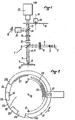
- the shooting assembly 1 shown in FIG. 1, comprises a light source of great luminance 2, which associated with a condenser 3, emits a beam 4 of parallel rays, passing through excitation filters 5
- the beam 4 thus filtered strikes a dichroic mirror 6 which deflects it at 90 ° and transmits it to a lens 7 which concentrates said beam on a localized area 8, in which a fluorescent phenomenon appears.
- This localized area can be a part of a blade or a cell of a plate, this blade or plate 9 being carried by a plate 10.
- the plate 9 comprises a plurality of cells 8 to be examined, provision is made (see FIGS. 9 to 11) a mechanism for relative movement of the plate 10 relative to the objective 7, so as to cycle through each of the cells 8 in turn under said objective 7 (see the mechanism 37 in FIG. 3) .
- fluorescence remission generated by the phenomenon of the localized area 8 is taken up by the objective 7 which forms it into a parallel beam 11, transmitted with the reflected part of the beam 4, to the dichroic mirror 6, which deflects the reflected part of the beam 4 towards the source 2.
- the fluorescence beam 11 then passes through stop filters 12 and an optic 13.
- a second dichroic mirror 14 deflects part of the beam 11 towards an eyepiece 15, behind which the eye 16 can be placed of an observer.
- the beam 11 forms an image of the zone 8 on the photocathode of a shooting tube 17, a disc 18 which can rotate around its axis 19 under the action of a motor 20, being interposed on the path of the beam 11 transmitted to the shooting tube 17.
- the dichroic mirror 14 and the eyepiece 15 are not essential and could be omitted.
- the structure of the assembly 1 in FIG. 1 is such that the area 8 is illuminated by the reflected part of the beam 4.
- this arrangement is not limiting and the area 8 could, for example , be examined by transparency rather than by reflection, the elements 12, 13 and 17 to 20 then being on the opposite side of the objective 7 relative to the plate 10.
- the source 2 can be of the types commercially known under the names HB0 50, HBO 100 or HBO 200, capable of providing on the zone 8 an illumination of the order of 50,000 to 100,000 lux, so that, the fluorescence reemissions having a yield of the order of 1/100 to 1/1000, the beam 11 may have an illumination of a few hundred lux.
- the excitation filters 5 can be chosen from those commercially known under the names BG 12, LP 480 or KP 490; they are then intended to provide maximum excitation in the blue (between 450 and 500 nm) and to very strongly attenuate the radiation above 500 nm.
- the dichroic mirror 6 is provided in this application to allow the yellow wavelengths of the beam 11 to pass in the direction of the shooting tube 17, but to return the blue radiation of the reflected beam 4 to the source 2.
- the action of the dichroic mirror 6 is reinforced by the stop filters 12 (for example of the type known commercially under the name LP 520) which cut the blue and -allows only radiation of wavelength greater than 500 nm, thus acting as a high-pass filter.
- the optic 13, for example of the OPTAVAR type aims to move the image focus of the objective 7 to give a more uniform illumination of the object examined.
- the disc 18, made of a black color material opaque to the radiation of the beam 11 has a large peripheral notch 21, as well as two red filters 22 and green 23 peripheral.
- the notch 21 and the filters 22 and 23 are arranged on the disc 18 so that they can be brought successively vertically above the shooting tube 17, when the said disc rotates (arrow F) under the action of the motor 20 ; the end 21a of the notch 21 is separated from the filter 22 by an opaque part 24 of the device 18; similarly, the filters 22 and 23 are separated from each other by an opaque part 25 of the disc 18, while another opaque part 26 of the disc 18 is disposed between the start of the notch 21 and the filter 23.
- the opaque parts 24, 25 and 26 are intended to obscure the tube 17 between two measurements so as to discharge it and partly avoid the effect of its own remanence. An anti-persistence effect could also be obtained by blocking the operation of the tube between two measurements.
- windows or reflective zones are formed in the disc 18 so as to be able to cooperate during the rotation of the latter with fixed opto-electronic devices. 30, 31 and 32 (see also Figure 3) for synchronization purposes, as will be described below.
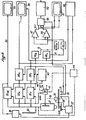
- the video signals coming from the tube 17, after preprocessing in a device 35 R are stored in a red memory 38 R.
- the video signals coming from the tube 17, after pretreatment in a device 35y are stored in a green memory 38 V.
- the memories 38 R and 38y are of the so-called "refreshed memory" type.
- the system according to the invention thus makes it possible to use only one shooting tube for green and for red, so that all the problems of superimposition and dispersion of characteristics usually encountered in films are eliminated.
- the shooting tube 17 must have a very high sensitivity and, in addition, it must be possible to vary this sensitivity significantly. Also, it is advantageous that this shooting tube is of the type comprising an incorporated electron multiplier, in addition to the usual image analyzer of VIDICON tubes. Like this, the tube can have a significant gain, of the order of 1,500 to 2,500, but variable depending on the acceleration voltage of the electron multiplier.
- tubes used commercially known under the names of NOCTICON 9655, NOCTICON 9559 and SUPER NOCTICON have been used with satisfaction.
- the acceleration voltage of the electron multiplier can vary from 3,000 to 9,000 volts for example, causing a variation in sensitivity in a ratio of 1 to 400. They allow images with a illumination of 10 -5 lux and formed on their 25 mm diameter photocathode.
- the sensitivity of the shooting tube 17 is thus adjusted or controlled with precision and the control of this sensitivity also controls the various corrections necessary to obtain good quantification.
- shooting tubes with high variable sensitivity of the type mentioned above have the disadvantage of having a high remanence, so that the weak signals are excessively amplified while the strong signals are little affected.
- the system according to the invention comprises a device 41 for adjusting the THT of the shooting tube 17, that is to say the amplification gain of the latter.
- the device 41 can be controlled manually, by actuating a member 42, the operator adjusting the position of the member 42 as a function of the indications on the amplitude of the video signals output from the tube 17, which in turn are given by a view meter 43.
- the adjustment can be automatic by means of a device 44 receiving the output signals from the shooting tube 17.
- the device 41 for controlling the high voltage of the multiplier element of electrons in tube 17 also controls the importance of correcting the levels of the black and white, red and green backgrounds via a line 44A slaving the individual gains of the devices 35 NB , 35 R and 35 V to the gain of the shooting tube 44.
- the illumination of a light area delimited by edges is more intense in the center than in the vicinity of said edges, so that, transversely to said area, the illumination thereof has the shape of a dome.
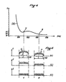
- FIG. 4 the curve (A) of weakening of the illumination E (in lux) of a zone 8 is represented as a function of the wavelength ⁇ (in m) of the light received from this zone .
- this weakening is greater for red than for green.
- Figure 5a we represent the illumination E along the width L of an area 8, we see that the bottom of this area has the shape of a dome D, from which appear the P points of fluorinated phenomena.
- the system according to the invention comprises a generator 45 emitting signals AD of inverse form of said domes.
- the generator 45 is connected to the gain control device 41 of the tube 17, so that the signals AD are of a form suitable for said gain.
- the signals AD are transmitted to the various preprocessing devices 35 NB , 35 R and 35 V , in which they are added to the signals D + P received from the tube 17. It results in the disappearance of the dome effect (see Figure 5b).
- the device 41 via the line 44A, it is possible to bring, as indicated above, the green and red signals to the same level (FIG. 5c).
- the device 45 provides a correction not only in the direction of the lines, but also in the direction of the frames.
- the red and green signals read from the memories 38 R and 38 V are addressed with two subtractors 47 and 48, respectively delivering to their outputs RV and VR signals which are transmitted to a computer 49, controlled by the opto-electronic device 32, then to a device for displaying the results 50 and from there to a computer (not shown).
- these RV and VR signals give a colored image on a color television screen 51.
- each of the automatic background correction devices 46 R and 46 v includes an integrator 52, a rectifier 53, possibly an amplifier 54 and a subtractor 55 receiving on the one hand the signal from the chain 52, 53 , 54 and on the other hand directly the signal from memories 38 R or 38y.
- the structure of the 46 R and 46 V devices is due to the observation that the fluorescent phenomena observed (points P in FIG. 5) are small compared to the total surface of the zone 8 observed: for example, they represent only a few ⁇ m 2 of this total surface which is of the order of a few mm 2. Also, the integration of the total signal carried out by the integrators 52 makes the useful signal P disappear so as to give only the background. However, to avoid cumulative integration, it is essential to block the operation of the integrators 52 between each frame, which is done by means of a command 56. The signal integrated by the integrators 52 is then rectified by the rectifiers 53 which give a uniform direct voltage, which, possibly amplified by the amplifiers 54, is subtracted, in the subtractors 55, from the red and green signals.
- the signals should be either red or green.
- the RV and VR subtractions are performed downstream of the devices 46 R and 46 V via the subtractors 47 and 48.
- the signal RY represents the red contained in zone 8
- the signal VR represents the green contained in zone 8.
- the colored image on the screen 51 is therefore a theoretical image of zone 8
- the signals leaving the memories 38 R and 38 V may include artefacts, that is to say parasitic signals, which do not correspond to the reality of the object that we want to observe.
- artefacts that is to say parasitic signals, which do not correspond to the reality of the object that we want to observe.
- the artifacts are all the objects visible on the preparation, but foreign to the reaction studied: they can consist of greasy traces of poorly cleaned slides, lumps of poorly filtered buffer, etc. .. and they often produce much brighter and larger signals than the elements of the reaction under consideration.
- an AT artefact is represented intervening in the middle of the useful signals P. It will be noted that because of the limited storage capacity in the memories 38 R and 38 V , such an AT artefact is already clipped at a level S.
- the system according to the invention comprises two devices 52 R and 52 y receiving the signals coming from the memories 38 R and 38 V respectively and sending corrected signals to the subtractors 47 and 48 respectively.
- each of the 52 R anti-artifact devices or 52 V comprises two parallel channels, namely a channel comprising from input to output, a delay line 57 and two adders 58 and 59, and a channel comprising, also from input to output, a possible amplifier 60, a clipper 61, an inverting amplifier 62 and a delay line 63.
- Links 64 and 65 are provided, respectively between the output of the inverting amplifier 62 and the adder. 58, and between the line output delay 63 and the adder 59. The operation of the devices 52 R and 52 V is described with reference to FIGS. 8b and 8g.
- the clipper 61 takes, in the artifact AT, the part 66 located between the level s of the useful signals P and the maximum level S (imposed by the memories 38 R and 38 V ) to make an isolated signal (see the Figure 8b).
- This part 66 of the AT signal is amplified and inverted by the inverting amplifier 62 to become an inverted slot 67 (see FIG. 8c).
- the inverted slot 67 is added to the AT + P signal, delayed by the delay line 57, so that the front portion 68 of the AT signal is eliminated by said slot (see FIGS. 8d and 8e). Only the rear part 69 then remains of the signal AT (FIG. 8e).
- the signal of FIG. 8e is added to the inverted slot 67, delayed by the delay line 63, so that the rear part 69 is eliminated (FIG. 8f).
- the video recorder 40 can be of any usual type capable of recording different colored signals. However, it is also possible to use a simple black and white video recorder by alternately assigning the even (or odd) frames to one of the colors (red or green) and the odd (or even) frames to the other of said colors (green or red).
- FIG. 9a A simple way of carrying out the necessary automatisms is shown on Figures 9a, 9b and 10, where we see that we have arranged a complementary thin plate 70, integral with the blade holder device 71 in which the blade to be examined 72 is immobilized.
- This complementary plate comprises, on the left of the operator in FIG. 10 (but on the right if desired), slides 73 and 73 ′, into which mobile auxiliary plates 74 (such as that shown in FIG. 10) can be inserted , lla and llb) whose movement is limited at the front by a stopper 73 ".
- This complementary plate 70 is itself inserted between two housings, 75 for the upper part and 76 for the lower part (shown in FIG. 9), and containing an optoelectronic device constituted by sets of photodiodes and "LED" diodes operating either by reflection or by transparency.
- an optoelectronic device constituted by sets of photodiodes and "LED" diodes operating either by reflection or by transparency.
- a small diameter cylinder 77 comprising for example inside a LED diode at the top and a lens at the lower end, so that a light point 78 appears on the image cell 78 'of the movable auxiliary plate 74. It can be seen in FIG.
- the mobile auxiliary plate 74 includes, on the one hand, the visible image 78 ′ of the alveoli, such as the real alveoli of the blade 72 appear under the microscope, and on the other hand, an assembly made up either of reflective elements 79, or slots allowing the transmission of a signal using LED type sources, said signal being collected by photodiodes not shown contained in the housing 76. With this assembly, all combinations of displacement are thus possible. Finally, it will be noted that the elements may represent various configurations but that these will simply have to be arranged according to the desired program.
- the operator will send a pulse. If the focusing is automatic, it will itself send the command pulse to start the sequences and to reset the counters and the display device 50.
- the disc 18 is stopped, it is immobilized thanks to an optoelectronic device 30 at the output of the filter-holder devices and at the start of the black and white analysis sequence (track 29 of the disc 18).
- the disc 18 starts up and the turntable moves in X.
- the turntable 10 will be immobilized again during the sequential storage of red then green and will start again automatically at the end of this operation thanks to the optoelectronic device 30 coming from the disc 18.
- all of the image cells such as 78 ′ constitute means of visualization of the real cells of the blade 72 and that all of the elements such 79 constitutes control means for judgment and read on areas located in the blade 72, cooperating with the optoelectronic device 30 of the disk 18 and the optoelectronic device 75 for movements in X
- the computer sends a signal which, on the one hand, will interrupt the storage, on the other hand, will "block” the shooting tube 17 until the start of the next cell where the same cycle will be repeated, and so on during the five cells of the first row.
- the optoelectronic device located inside the box 76 identifying the end of the X analysis thanks to the reflective track 81 carried by the underside of the auxiliary plate 74 (see FIG. 11b) the movement in Y of the plate to the lower row, where the cycle of movement in X will be repeated, for example, in reverse.
- the aforementioned opto-electronic device will detect the reflective track 82 indicating the end of analysis and allowing, in cooperation with the reflective marker 83, the return of the blade 72 substantially at the initial position.
- the system according to the invention allowing the quantification of the results, some examples are given below.
- the sampling method has already been mentioned on page 25 lines 3 and 4 and page 26 lines 1 and 2, and, for the convenience of the operation, we have seen that it has been limited to 10 samples.
- the computer will therefore record 10 successive values corresponding to the amplitude of the signals, in "peak” or integrated value, after correction, representing the positive part of (VR) on the one hand, and the positive part of (RV) of somewhere else.
- the calculator will give an average value of the 10 samples taken from a cell and corresponding to one of the dilutions.
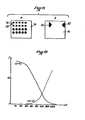
- Figure 12 gives the general appearance of the curves obtained for a titration, where the dilutions were represented on the abscissa on a logarithmic scale and the signal intensities (V-R) and (R-V) were plotted on the ordinate on a linear scale. Note on these curves the rapid descent of + (V-R), and an ascent of + (R-V).
- Another quantification method may be necessary for certain applications, for example the determination of the HLA group, where no titration is carried out.
- the computer can also determine the ratios of these areas to the total field.
Landscapes
- Health & Medical Sciences (AREA)
- Nuclear Medicine, Radiotherapy & Molecular Imaging (AREA)
- Physics & Mathematics (AREA)
- Life Sciences & Earth Sciences (AREA)
- Chemical & Material Sciences (AREA)
- Analytical Chemistry (AREA)
- Biochemistry (AREA)
- General Health & Medical Sciences (AREA)
- General Physics & Mathematics (AREA)
- Immunology (AREA)
- Pathology (AREA)
- Investigating, Analyzing Materials By Fluorescence Or Luminescence (AREA)
- Eye Examination Apparatus (AREA)
Applications Claiming Priority (2)
| Application Number | Priority Date | Filing Date | Title |
|---|---|---|---|
| FR8215054A FR2532756A1 (fr) | 1982-09-03 | 1982-09-03 | Systeme pour l'observation et la quantification automatiques de phenomenes susceptibles d'etre detectes par fluorescence |
| FR8215054 | 1982-09-03 |
Publications (2)
| Publication Number | Publication Date |
|---|---|
| EP0106721A2 true EP0106721A2 (de) | 1984-04-25 |
| EP0106721A3 EP0106721A3 (de) | 1986-01-15 |
Family
ID=9277215
Family Applications (1)
| Application Number | Title | Priority Date | Filing Date |
|---|---|---|---|
| EP83401710A Withdrawn EP0106721A3 (de) | 1982-09-03 | 1983-08-26 | System zur Beobachtung und automatische Mengenbestimmung von durch Fluoreszenz erfassbaren Ereignissen |
Country Status (6)
| Country | Link |
|---|---|
| US (1) | US4573195A (de) |
| EP (1) | EP0106721A3 (de) |
| JP (1) | JPS59160743A (de) |
| CA (1) | CA1217649A (de) |
| ES (1) | ES525330A0 (de) |
| FR (1) | FR2532756A1 (de) |
Cited By (4)
| Publication number | Priority date | Publication date | Assignee | Title |
|---|---|---|---|---|
| WO1986002730A1 (en) * | 1984-10-22 | 1986-05-09 | Hightech Network Sci Ab | A fluorescence imaging system |
| GB2178623A (en) * | 1985-07-26 | 1987-02-11 | Zeiss Jena Veb Carl | An arrangement for the pictorial display and analysis of fluorescent signals |
| WO1987004804A1 (en) * | 1986-02-11 | 1987-08-13 | The University Of Massachusetts | Microspectrofluorimeter |
| EP0339582A3 (en) * | 1988-04-26 | 1990-11-22 | Olympus Optical Co., Ltd. | Fluorescence microscope system |
Families Citing this family (34)
| Publication number | Priority date | Publication date | Assignee | Title |
|---|---|---|---|---|
| JPS60256443A (ja) * | 1984-05-31 | 1985-12-18 | オムロン株式会社 | 画像計測装置 |
| USRE34782E (en) * | 1985-07-01 | 1994-11-08 | Diatron Corporation | Fluorometer |
| US4877965A (en) * | 1985-07-01 | 1989-10-31 | Diatron Corporation | Fluorometer |
| US4859063A (en) * | 1986-02-11 | 1989-08-22 | University Of Massachusetts Medical Center | Imaging microspectrofluorimeter |
| US4943142A (en) * | 1986-02-11 | 1990-07-24 | University Of Massachusetts Medical Center | Imaging microspectrofluorimeter |
| US5009488A (en) * | 1986-02-11 | 1991-04-23 | University Of Massachusetts Medical Center | Filter accessory for an imaging microspectrofluorimeter |
| US4791310A (en) * | 1986-10-02 | 1988-12-13 | Syracuse University | Fluorescence microscopy |
| JPS6435373A (en) * | 1987-07-31 | 1989-02-06 | Fujirebio Kk | Method and device for high-sensitivity immunoassay |
| US5029222A (en) * | 1987-09-02 | 1991-07-02 | Fujitsu Limited | Photoelectron image projection apparatus |
| JP2683934B2 (ja) * | 1988-07-29 | 1997-12-03 | 富士レビオ株式会社 | 免疫測定方法 |
| EP0363931B1 (de) * | 1988-10-11 | 1995-10-04 | E.I. Du Pont De Nemours And Company | Laserabtastmikroskop und Anwendungsverfahren |
| EP0405480A3 (en) * | 1989-06-28 | 1991-05-08 | Kirin Beer Kabushiki Kaisha | Method of and apparatus for detecting microorganisms |
| US5053626A (en) * | 1989-09-29 | 1991-10-01 | Boston University | Dual wavelength spectrofluorometer |
| JP2525678B2 (ja) * | 1989-10-03 | 1996-08-21 | 富士写真フイルム株式会社 | 免疫測定装置 |
| JP2654698B2 (ja) * | 1989-10-02 | 1997-09-17 | 富士写真フイルム株式会社 | 免疫測定装置 |
| US5093866A (en) * | 1990-02-09 | 1992-03-03 | Hamilton Equine Associates Limited | Fluorescence and motility characterization system for cells, bacteria, and particles in fluids |
| US5296911A (en) * | 1992-07-16 | 1994-03-22 | Schiapparelli Biosystems, Inc. | Optical test system for a chemical analyzer |
| DE4230724C1 (de) * | 1992-09-14 | 1993-10-14 | Leica Mikroskopie & Syst | Verfahren und Vorrichtung zur Belichtungssteuerung für die Fluoreszenzmikrofotografie |
| US5422730A (en) * | 1994-03-25 | 1995-06-06 | Barlow; Clyde H. | Automated optical detection of tissue perfusion by microspheres |
| US5682244A (en) * | 1994-03-25 | 1997-10-28 | Barlow; Clyde H. | Automated optical detection of tissue perfusion by microspheres |
| US5528521A (en) * | 1994-05-27 | 1996-06-18 | Hoffmann-La Roche Inc. | Titration emulation system and method |
| EP0775908A1 (de) * | 1995-11-21 | 1997-05-28 | Advanced Biological Products Inc. | Quantisierung der Fluoreszenz |
| EP1019686B1 (de) * | 1997-07-12 | 2009-08-26 | Roper Industries, Inc. | Multispektraler zweidimensionaler bildgebeuder spekteometer |
| US6169289B1 (en) | 1998-01-27 | 2001-01-02 | Wisconsin Alumni Research Foundation | Signal enhancement for fluorescence microscopy |
| US5982497A (en) * | 1998-07-09 | 1999-11-09 | Optical Insights, Llc | Multi-spectral two-dimensional imaging spectrometer |
| FR2807543B1 (fr) | 2000-04-06 | 2004-11-05 | Imstar S A | Appareil d'imagerie associe a une base de donnees images |
| US6687000B1 (en) | 2000-06-26 | 2004-02-03 | Wisconsin Alumni Research Foundation | Photon-sorting spectroscopic microscope system |
| US6856466B2 (en) | 2001-07-05 | 2005-02-15 | Science & Engineering Associates, Inc. | Multiple imaging system |
| US20060073470A1 (en) * | 2002-05-30 | 2006-04-06 | Naohiro Noda | Method of counting microorganisms or cells |
| US7031084B2 (en) * | 2003-07-23 | 2006-04-18 | Eastman Kodak Company | Imaging system using combined dichroic/high-pass filters |
| CN102159936A (zh) * | 2008-09-18 | 2011-08-17 | 株式会社岛津制作所 | 荧光图像检测装置以及荧光图像检测方法 |
| DE102009024941A1 (de) * | 2009-06-09 | 2010-12-23 | Carl Zeiss Surgical Gmbh | Beleuchtungsvorrichtung und medizinisch-optisches Beobachtungsgerät |
| EP2309302A1 (de) * | 2009-10-09 | 2011-04-13 | Deutsches Krebsforschungszentrum | Lokalisierung lichtemittierendre Moleküle mit unbekannter Orientierung |
| TWI463942B (zh) * | 2012-07-18 | 2014-12-11 | Yen Dong Wu | 一種促進植物生長之方法 |
Family Cites Families (12)
| Publication number | Priority date | Publication date | Assignee | Title |
|---|---|---|---|---|
| US3131257A (en) * | 1961-02-09 | 1964-04-28 | Ampex | Signal processing means |
| US3389221A (en) * | 1964-04-29 | 1968-06-18 | Westinghouse Electric Corp | Television brightness compensation system |
| US3499109A (en) * | 1965-07-28 | 1970-03-03 | Sony Corp | Avoidance of resolution degradation due to residual image phenomena in television cameras |
| US3612762A (en) * | 1969-03-26 | 1971-10-12 | Itt | Automatic gain control system for camera tube |
| JPS505527B1 (de) * | 1969-05-31 | 1975-03-05 | ||
| US4207554A (en) * | 1972-08-04 | 1980-06-10 | Med-El Inc. | Method and apparatus for automated classification and analysis of cells |
| US3918812A (en) * | 1973-05-07 | 1975-11-11 | Us Energy | Diagnoses of disease states by fluorescent measurements utilizing scanning laser beams |
| GB1471147A (en) * | 1973-07-16 | 1977-04-21 | Nutritional Res Unit Ltd | Image analysers |
| DE2437984B2 (de) * | 1974-08-07 | 1976-06-10 | Wilhelm Will Kg, Optisches Werk, 6331 Nauborn | Verfahren zur kontrastverbesserung eines optischen mikroskopes |
| US4048616A (en) * | 1975-12-03 | 1977-09-13 | Geometric Data Corporation | Pattern recognition system with keyboard entry for adaptive sensitivity |
| US4437118A (en) * | 1977-08-18 | 1984-03-13 | U.S. Philips Corporation | Pyroelectric vidicon with improved signal-to-noise ratio |
| JPS5562423A (en) * | 1978-11-02 | 1980-05-10 | Olympus Optical Co Ltd | Projecting device |
-
1982
- 1982-09-03 FR FR8215054A patent/FR2532756A1/fr active Granted
-
1983
- 1983-08-26 EP EP83401710A patent/EP0106721A3/de not_active Withdrawn
- 1983-08-29 CA CA000435597A patent/CA1217649A/en not_active Expired
- 1983-08-31 US US06/528,007 patent/US4573195A/en not_active Expired - Fee Related
- 1983-09-02 ES ES525330A patent/ES525330A0/es active Granted
- 1983-09-03 JP JP58161232A patent/JPS59160743A/ja active Pending
Cited By (6)
| Publication number | Priority date | Publication date | Assignee | Title |
|---|---|---|---|---|
| WO1986002730A1 (en) * | 1984-10-22 | 1986-05-09 | Hightech Network Sci Ab | A fluorescence imaging system |
| GB2178623A (en) * | 1985-07-26 | 1987-02-11 | Zeiss Jena Veb Carl | An arrangement for the pictorial display and analysis of fluorescent signals |
| GB2178623B (en) * | 1985-07-26 | 1989-08-23 | Zeiss Jena Veb Carl | An arrangement for the pictorial display and analysis of fluorescent signals |
| WO1987004804A1 (en) * | 1986-02-11 | 1987-08-13 | The University Of Massachusetts | Microspectrofluorimeter |
| US4744667A (en) * | 1986-02-11 | 1988-05-17 | University Of Massachusetts | Microspectrofluorimeter |
| EP0339582A3 (en) * | 1988-04-26 | 1990-11-22 | Olympus Optical Co., Ltd. | Fluorescence microscope system |
Also Published As
| Publication number | Publication date |
|---|---|
| JPS59160743A (ja) | 1984-09-11 |
| US4573195A (en) | 1986-02-25 |
| FR2532756B1 (de) | 1985-03-08 |
| ES8405151A1 (es) | 1984-05-16 |
| EP0106721A3 (de) | 1986-01-15 |
| ES525330A0 (es) | 1984-05-16 |
| FR2532756A1 (fr) | 1984-03-09 |
| CA1217649A (en) | 1987-02-10 |
Similar Documents
| Publication | Publication Date | Title |
|---|---|---|
| FR2532756A1 (fr) | Systeme pour l'observation et la quantification automatiques de phenomenes susceptibles d'etre detectes par fluorescence | |
| CA2570630C (fr) | Procede et systeme d'imagerie microscopique de fluorescence fibree multimarquage | |
| CN1265188C (zh) | 成份分析 | |
| EP1114348B9 (de) | Vorrichtung zur Beobachtung des Inneren eines Körpers mit verbesserter Beobachtungsqualität | |
| EP4185914B1 (de) | Systeme und verfahren zur durchführung einer mikroskopischen analyse einer probe | |
| EP0751740B1 (de) | Bildformungsanordnung mittels infrarot-fluorezenz für ein endoskop oder fiberskop | |
| EP1875209B1 (de) | Fluoreszenzabbildungsvorrichtung mit Reflexion bei zwei Wellenlängen | |
| CA2491748C (fr) | Procede et appareillage d'imagerie de fluorescence haute resolution par fibre optique et notamment d'imagerie confocale | |
| EP2351518B1 (de) | Perioperative bispektrale optische Sonde | |
| CA2471721C (fr) | Appareillage d'imagerie confocale notamment pour endoscope | |
| FR2537428A1 (fr) | Procede et dispositif pour produire une image du fond de l'oeil | |
| WO2002096281A1 (fr) | Procede et dispositif d'acquisition et de traitement d'images d'une dent | |
| FR2699677A1 (fr) | Procédé et dispositif de détermination de la couleur d'un objet transparent, diffusant et absorbant, tel en particulier qu'une dent. | |
| JP2005515473A (ja) | 分光診断方法とシステム | |
| EP3295153A1 (de) | Verfahren zur korrektur eines fluoreszenzbildes | |
| EP1164921B1 (de) | Einrichtung zur beobachtung eines körpers mit hoher auflösung | |
| EP1461601B1 (de) | Vorrichtung zur autofluoreszenzspektroskopie aus dem innern | |
| WO2007144542A1 (fr) | Dispositif d'imagerie optique | |
| EP3136151A1 (de) | Gerät zum beobachten der abgabe von licht von einer probe durch optische dynamische mikroskopie | |
| FR3164787A1 (fr) | Procédé de caractérisation de la trajectoire d’une particule mobile dans un échantillon | |
| EP4591108A1 (de) | Optisches mikroskop mit resonator |
Legal Events
| Date | Code | Title | Description |
|---|---|---|---|
| PUAI | Public reference made under article 153(3) epc to a published international application that has entered the european phase |
Free format text: ORIGINAL CODE: 0009012 |
|
| AK | Designated contracting states |
Designated state(s): AT BE CH DE GB IT LI LU NL SE |
|
| 17P | Request for examination filed |
Effective date: 19841003 |
|
| PUAL | Search report despatched |
Free format text: ORIGINAL CODE: 0009013 |
|
| AK | Designated contracting states |
Designated state(s): AT BE CH DE GB IT LI LU NL SE |
|
| 17Q | First examination report despatched |
Effective date: 19870611 |
|
| D17Q | First examination report despatched (deleted) | ||
| STAA | Information on the status of an ep patent application or granted ep patent |
Free format text: STATUS: THE APPLICATION IS DEEMED TO BE WITHDRAWN |
|
| 18D | Application deemed to be withdrawn |
Effective date: 19880525 |
|
| RIN1 | Information on inventor provided before grant (corrected) |
Inventor name: DE FRANCE, HENRI GEORGES |