EP0106773B1 - Vorrichtung zur gleichzeitigen Vergrösserung, und Entwicklung von Photos - Google Patents
Vorrichtung zur gleichzeitigen Vergrösserung, und Entwicklung von Photos Download PDFInfo
- Publication number
- EP0106773B1 EP0106773B1 EP83420157A EP83420157A EP0106773B1 EP 0106773 B1 EP0106773 B1 EP 0106773B1 EP 83420157 A EP83420157 A EP 83420157A EP 83420157 A EP83420157 A EP 83420157A EP 0106773 B1 EP0106773 B1 EP 0106773B1
- Authority
- EP
- European Patent Office
- Prior art keywords
- paper
- disposed
- unit
- pins
- knife
- Prior art date
- Legal status (The legal status is an assumption and is not a legal conclusion. Google has not performed a legal analysis and makes no representation as to the accuracy of the status listed.)
- Expired
Links
- 238000007639 printing Methods 0.000 title claims description 11
- 230000003287 optical effect Effects 0.000 claims description 20
- 238000005520 cutting process Methods 0.000 claims description 9
- 238000012384 transportation and delivery Methods 0.000 claims description 5
- 230000001976 improved effect Effects 0.000 claims description 3
- 238000011282 treatment Methods 0.000 claims description 3
- 238000001914 filtration Methods 0.000 claims description 2
- 238000011161 development Methods 0.000 description 8
- 239000003795 chemical substances by application Substances 0.000 description 4
- 229910000842 Zamak Inorganic materials 0.000 description 2
- 230000008859 change Effects 0.000 description 2
- 238000010276 construction Methods 0.000 description 2
- 230000033001 locomotion Effects 0.000 description 2
- 239000000463 material Substances 0.000 description 2
- 238000000034 method Methods 0.000 description 2
- 239000004033 plastic Substances 0.000 description 2
- 229920003023 plastic Polymers 0.000 description 2
- 230000008569 process Effects 0.000 description 2
- 101000759226 Homo sapiens Zinc finger protein 143 Proteins 0.000 description 1
- 240000008042 Zea mays Species 0.000 description 1
- 102100023389 Zinc finger protein 143 Human genes 0.000 description 1
- 229910002056 binary alloy Inorganic materials 0.000 description 1
- 238000001035 drying Methods 0.000 description 1
- 230000002349 favourable effect Effects 0.000 description 1
- 238000009434 installation Methods 0.000 description 1
- 230000000670 limiting effect Effects 0.000 description 1
- 238000004519 manufacturing process Methods 0.000 description 1
- 239000002991 molded plastic Substances 0.000 description 1
- 238000007747 plating Methods 0.000 description 1
- 230000000750 progressive effect Effects 0.000 description 1
- 230000000284 resting effect Effects 0.000 description 1
- 238000007789 sealing Methods 0.000 description 1
- 238000003892 spreading Methods 0.000 description 1
- 230000007480 spreading Effects 0.000 description 1
- 238000012360 testing method Methods 0.000 description 1
- 238000007514 turning Methods 0.000 description 1
- 238000005406 washing Methods 0.000 description 1
Images


Classifications
-
- G—PHYSICS
- G03—PHOTOGRAPHY; CINEMATOGRAPHY; ANALOGOUS TECHNIQUES USING WAVES OTHER THAN OPTICAL WAVES; ELECTROGRAPHY; HOLOGRAPHY
- G03B—APPARATUS OR ARRANGEMENTS FOR TAKING PHOTOGRAPHS OR FOR PROJECTING OR VIEWING THEM; APPARATUS OR ARRANGEMENTS EMPLOYING ANALOGOUS TECHNIQUES USING WAVES OTHER THAN OPTICAL WAVES; ACCESSORIES THEREFOR
- G03B27/00—Photographic printing apparatus
- G03B27/32—Projection printing apparatus, e.g. enlarger, copying camera
Definitions
- the invention relates to an automatic device for the simultaneous printing and development of photographs, particularly in color.
- the invention overcomes these drawbacks.
- the support plate (30) is fixed.
- the cutting part (27) and more precisely the lower edge of this fixed knife (25) delimit on the sensitive paper debited (24), bearing on the plate (30), the part which will be exposed by the beam (39) from exposure set A, and more specifically from objective (5).
- the knife (25) forms a mask for the light beam (39). This arrangement is very favorable for obtaining photographs whose edges are sharp and for which only the optimal surface of paper is used.
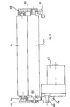
- the debtor unit (see Figures 3-4) comprises two flanges (45-46) arranged on each of the internal walls of the debtor unit (14).
- the end of the rollers (20-21) rests on bearings or bearings.
- a geared motor (47) drives an output shaft (48) a pinion (49) which engages a pinion (50) carried by the drive roller (20).
- the disengageable pressure roller (21) is mounted idly at the end of a connecting rod (51) articulated at its other end (52) on the flange (45).
- a return spring (53) is fixed at one end (54) to the flange (45) and at its other end (55) to the connecting rod (51), so as to keep the driven roller (21) in pressure against ( 20).
- the connecting rod (51) has on the inside a ramp (60) in the form of a cam intended to cooperate with a shaft (61) parallel to the two rollers (20) and (21
- This shaft (61) has a notch (62) facing the ramp (60) intended to cooperate with the ramp (60)
- the notch (62) presses on the ramp (60) which spreads the connecting rod (51). By thus spreading the rollers, it is therefore possible to introduce the sensitive paper (12).
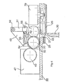
- the chisel (see Figure 5) works as follows.
- the fixed knife (25) is screwed onto the bottom (22) of the housing (14) in the immediate vicinity of the slot (23).
- the movable knife (26) whose cutting wire (69) is inclined or has a very open V shape is formed by a plate secured by two axes (71) and (72) of two oscillating plates (73) and (74 ) horizontal connected together by a connecting rod (75) bearing on fixed but articulated axes (76-77).
- This connecting rod (75) is driven in movement by another connecting rod (78) also supported at (77) connected to the control axis of a geared motor (79).
- the face (27) is advantageously located directly above the line of tangency of the two rollers (20-21).
- the free end of the drive roller (20) carries a segmented disc (80) cooperating in known manner with an opto-electronic reader (81).
- the two geared motors (47) and (79) are controlled in synchronism by a suitable conventional member, not shown.
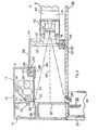
- the optical assembly A essentially comprises the film holder (4) and the objective (5).
- the film holder is of the type described in European patent application 0064015 cited in the preamble.
- This film holder essentially comprises a receptacle (40) for the filter assembly (2-3) and a chamfered passage for the film to be drawn.
- the receptacle (40) is associated with another housing (42) at the end of which the objective (5) is disposed.
- a photoelectric cell (37), for example of the CdS type, is associated with a light meter to make it possible to measure the quantity of light passing through the film and this in order to correct the exposure time of the films on or under exposed.
- This optical assembly A is mounted on a rigid panel (43) made of plastic. This panel (43) is snapped onto the front input face (44) of the frame. This panel (43) has at its base a multi-pin electrical connector (56), for example of the twenty-pin type, ref. STAF of HARTING ELEKTONIK GmbH.
- the male pins (57) of the contactor (56) are fixed on the plate (43) while the female pins (58) are fixed on the frame (59) of the assembly in dark room B.
- a window (63) is formed in the frame (59) on the entry face in order to allow the light beam (39) coming from the objective (5) to pass.
- the frame (59) and the assembly holder (43) are made of molded plastic.
- the upper face of the frame (59) has a second opening (64) intended to receive an electrical contactor 65) similar to (56).
- An electronic control board, snapped into the frame of B carries the various electrical connection circuits and control elements, such as relays, electronic components, etc. This board, not shown, is connected to the electrical source.
- the window (63) must be large enough to admit the different types of optical assembly (4-5). Thus, if one wishes to obtain a small format, the objective (5) will then be placed at the top of the window (63), whereas on the other hand, if one wishes to achieve a larger format, it will rather be placed towards the bottom .
- the distance between the optical axis (66) and the paper cutting axis which is delimited by the fixed knife (25) and more precisely (27) on which the image to be reproduced is equal to half the length to be cut, which thus avoids any adjustment and consequently reduces the sources of errors.
- the optical assembly (4-5) relates to the body (42) of the identification means, such as for example the format of the film intended to be printed and the format of printing.
- the electrical contactor (56) is connected by its male pins (57) respectively: to the exposure lamp (1), to the motor for advancing the film to be printed, and to the measuring cell (37) of the quantity of light.
- the other male pins (57) are used to identify the optical assembly. To do this, when the assembly is in place, if the current passes through a determined pin, this means that it is indeed the appropriate film holder for such format and for such film which is in place. Otherwise, the electric current would not pass.
- the female pins (58) are connected to the electronic control board.
- the female pins (68) of this electrical connector (65) are also connected to the electronic control plate.
- the film advance motor presents the following view and the cycle begins again.
- optical assembly (4-5) associated with the electrical connectors (56-65) cooperating with the electronic plate, the operator will be able to make films or films of special formats without having to use a different material, but simply by playing on the choice of the optical assembly (4-5).
- this device makes it possible to process very varied formats. It is furthermore of simple construction and easy to operate. This device is reliable, compact and can indifferently process black and white or color photos.
Landscapes
- Physics & Mathematics (AREA)
- General Physics & Mathematics (AREA)
- Projection-Type Copiers In General (AREA)
- Photographic Processing Devices Using Wet Methods (AREA)
- Cameras Adapted For Combination With Other Photographic Or Optical Apparatuses (AREA)
Claims (3)
Applications Claiming Priority (4)
| Application Number | Priority Date | Filing Date | Title |
|---|---|---|---|
| FR8216841A FR2534035A1 (fr) | 1982-10-05 | 1982-10-05 | Appareil debiteur de papier sensible pour dispositif automatique de tirage et/ou de developpement |
| FR8216841 | 1982-10-05 | ||
| FR8304698A FR2542880B1 (fr) | 1983-03-18 | 1983-03-18 | Dispositif perfectionne pour le tirage et le developpement simultanes de photographies |
| FR8304698 | 1983-03-18 |
Publications (2)
| Publication Number | Publication Date |
|---|---|
| EP0106773A1 EP0106773A1 (de) | 1984-04-25 |
| EP0106773B1 true EP0106773B1 (de) | 1987-06-03 |
Family
ID=26223095
Family Applications (1)
| Application Number | Title | Priority Date | Filing Date |
|---|---|---|---|
| EP83420157A Expired EP0106773B1 (de) | 1982-10-05 | 1983-09-29 | Vorrichtung zur gleichzeitigen Vergrösserung, und Entwicklung von Photos |
Country Status (4)
| Country | Link |
|---|---|
| US (1) | US4547065A (de) |
| EP (1) | EP0106773B1 (de) |
| JP (1) | JPS59119439U (de) |
| DE (1) | DE3371945D1 (de) |
Families Citing this family (3)
| Publication number | Priority date | Publication date | Assignee | Title |
|---|---|---|---|---|
| US4786946A (en) * | 1988-01-21 | 1988-11-22 | Eastman Kodak Company | Paper delivery system for photographic printer |
| US4947207A (en) * | 1988-12-05 | 1990-08-07 | Eastman Kodak Company | Apparatus for exposing photographic materials |
| DE19644255C1 (de) * | 1996-10-24 | 1998-04-30 | Steag Micro Tech Gmbh | Vorrichtung zum Behandeln von Substraten und Verwendung der Vorrichtung |
Family Cites Families (10)
| Publication number | Priority date | Publication date | Assignee | Title |
|---|---|---|---|---|
| US1157611A (en) * | 1912-12-12 | 1915-10-19 | George C Beidler | Photographing and developing apparatus. |
| DE1234121B (de) * | 1959-03-26 | 1967-02-09 | Agfa Ag | Optische Kopiervorrichtung mit einer zur Belichtungsmessung oder -regelung dienenden fotoelektrischen Einrichtung |
| US3308717A (en) * | 1964-02-19 | 1967-03-14 | Minolta Camera Kk | Enlarging and printing machine |
| US3335636A (en) * | 1964-12-31 | 1967-08-15 | Edward R Atkinson | Fully automated process camera |
| DE1942336B2 (de) * | 1968-08-30 | 1971-05-27 | Vorrichtung zum elektrostatischen drucken und damit durchge fuehrten verfahren | |
| US3685150A (en) * | 1970-07-27 | 1972-08-22 | Philip Morris Inc | Double edge safety razor embodying flexible blade pressure control |
| US3689150A (en) * | 1970-08-31 | 1972-09-05 | Robertson Photo Mechanix Inc | Automatic roll film camera |
| DE2050012C3 (de) * | 1970-10-12 | 1978-06-29 | Hoechst Ag, 6000 Frankfurt | Mikrofilmrückvergrößerungsgerät |
| US3737227A (en) * | 1971-09-20 | 1973-06-05 | Eastman Kodak Co | Print border control apparatus |
| JPS56122023A (en) * | 1980-02-29 | 1981-09-25 | Dainippon Screen Mfg Co Ltd | Matching method between original picture and film at exposure position in process camera for roll film |
-
1983
- 1983-09-27 US US06/536,399 patent/US4547065A/en not_active Expired - Fee Related
- 1983-09-29 DE DE8383420157T patent/DE3371945D1/de not_active Expired
- 1983-09-29 EP EP83420157A patent/EP0106773B1/de not_active Expired
- 1983-10-05 JP JP1983154946U patent/JPS59119439U/ja active Pending
Also Published As
| Publication number | Publication date |
|---|---|
| JPS59119439U (ja) | 1984-08-11 |
| DE3371945D1 (en) | 1987-07-09 |
| EP0106773A1 (de) | 1984-04-25 |
| US4547065A (en) | 1985-10-15 |
Similar Documents
| Publication | Publication Date | Title |
|---|---|---|
| EP0296080B1 (de) | Integrierte automatische Vorrichtung zur gleichzeitigen und kontinuierlichen Filmentwicklung und Abziehen und Entwickeln von photographischen Bildern | |
| CA1088143A (en) | Reader-printer apparatus | |
| EP0064015B1 (de) | Automatische Vorrichtung zum Vergrössern und gleichzeitigen Entwickeln von Abdrücken | |
| EP0106773B1 (de) | Vorrichtung zur gleichzeitigen Vergrösserung, und Entwicklung von Photos | |
| FR2571198A1 (fr) | Restituteur d'images haute resolution autorisant le developpement en temps reel des films insoles | |
| FR2553530A1 (fr) | Dispositif pour l'exposition et la separation d'un materiau photographique en bande pour la production de copies a vif | |
| US3984849A (en) | Photographic color separation equipment | |
| FR2542880A1 (fr) | Dispositif perfectionne pour le tirage et le developpement simultanes de photographies | |
| US4478511A (en) | Film delivery and positioning device | |
| US3967898A (en) | Optical distortion device | |
| US3472590A (en) | Photocopy apparatus | |
| EP0262001A1 (de) | Photokopiergerät nach dem Baukastenprinzip zur Belichtung von Dokumenten | |
| FR2534035A1 (fr) | Appareil debiteur de papier sensible pour dispositif automatique de tirage et/ou de developpement | |
| CA1105306A (en) | Microfilm recording and developing apparatus | |
| US3615133A (en) | Photocopy apparatus | |
| JP2633396B2 (ja) | 画像形成装置および画像形成条件設定方法 | |
| EP0124463A1 (de) | Automatisches Vergrösserungs-Entwicklungsgerät zur Erhaltung von photographischen Bildern von Negativen | |
| CH624226A5 (de) | ||
| EP0088665A1 (de) | Kamera in Modulbauweise mit Vielfachunterteilung zur Herstellung von Mikrofichen | |
| FR2724739A1 (fr) | Installation automatique integree pour effectuer en continu le developpement de films photographiques et le tirage et le developpement d'epreuves photographiques | |
| FR2610423A1 (fr) | Procede et dispositif pour le tirage d'epreuves photographiques a partir d'un original | |
| FR2552897A1 (fr) | Dispositif pour le tirage et le developpement simultanes de photographies | |
| USRE31918E (en) | Photographic color separation equipment | |
| JPS59163949A (ja) | 画像読取装置 | |
| JPH0291637A (ja) | カラーテストチャートの設定方法およびこれを用いた画像形成装置 |
Legal Events
| Date | Code | Title | Description |
|---|---|---|---|
| PUAI | Public reference made under article 153(3) epc to a published international application that has entered the european phase |
Free format text: ORIGINAL CODE: 0009012 |
|
| AK | Designated contracting states |
Designated state(s): BE CH DE GB IT LI NL SE |
|
| RAP1 | Party data changed (applicant data changed or rights of an application transferred) |
Owner name: KIS PHOTO INDUSTRIE |
|
| 17P | Request for examination filed |
Effective date: 19841018 |
|
| ITF | It: translation for a ep patent filed | ||
| GRAA | (expected) grant |
Free format text: ORIGINAL CODE: 0009210 |
|
| AK | Designated contracting states |
Kind code of ref document: B1 Designated state(s): BE CH DE GB IT LI NL SE |
|
| PG25 | Lapsed in a contracting state [announced via postgrant information from national office to epo] |
Ref country code: NL Effective date: 19870603 |
|
| PG25 | Lapsed in a contracting state [announced via postgrant information from national office to epo] |
Ref country code: SE Effective date: 19870630 |
|
| REF | Corresponds to: |
Ref document number: 3371945 Country of ref document: DE Date of ref document: 19870709 |
|
| NLV1 | Nl: lapsed or annulled due to failure to fulfill the requirements of art. 29p and 29m of the patents act | ||
| R20 | Corrections of a patent specification |
Effective date: 19880115 |
|
| PLBE | No opposition filed within time limit |
Free format text: ORIGINAL CODE: 0009261 |
|
| STAA | Information on the status of an ep patent application or granted ep patent |
Free format text: STATUS: NO OPPOSITION FILED WITHIN TIME LIMIT |
|
| 26N | No opposition filed | ||
| PGFP | Annual fee paid to national office [announced via postgrant information from national office to epo] |
Ref country code: DE Payment date: 19890914 Year of fee payment: 7 |
|
| ITTA | It: last paid annual fee | ||
| PG25 | Lapsed in a contracting state [announced via postgrant information from national office to epo] |
Ref country code: LI Effective date: 19890930 Ref country code: CH Effective date: 19890930 Ref country code: BE Effective date: 19890930 |
|
| PGFP | Annual fee paid to national office [announced via postgrant information from national office to epo] |
Ref country code: GB Payment date: 19890930 Year of fee payment: 7 |
|
| BERE | Be: lapsed |
Owner name: KIS PHOTO INDUSTRIE Effective date: 19890930 |
|
| REG | Reference to a national code |
Ref country code: CH Ref legal event code: PL |
|
| PG25 | Lapsed in a contracting state [announced via postgrant information from national office to epo] |
Ref country code: GB Effective date: 19900929 |
|
| GBPC | Gb: european patent ceased through non-payment of renewal fee | ||
| PG25 | Lapsed in a contracting state [announced via postgrant information from national office to epo] |
Ref country code: DE Effective date: 19910601 |