EP0106836B1 - Dispositif pour l'avancement et/ou pour l'usinage d'une corde transportée continuellement - Google Patents
Dispositif pour l'avancement et/ou pour l'usinage d'une corde transportée continuellement Download PDFInfo
- Publication number
- EP0106836B1 EP0106836B1 EP19830890160 EP83890160A EP0106836B1 EP 0106836 B1 EP0106836 B1 EP 0106836B1 EP 19830890160 EP19830890160 EP 19830890160 EP 83890160 A EP83890160 A EP 83890160A EP 0106836 B1 EP0106836 B1 EP 0106836B1
- Authority
- EP
- European Patent Office
- Prior art keywords
- tools
- tool
- plane
- another
- located opposite
- Prior art date
- Legal status (The legal status is an assumption and is not a legal conclusion. Google has not performed a legal analysis and makes no representation as to the accuracy of the status listed.)
- Expired
Links
- 238000003754 machining Methods 0.000 title 1
- 239000000969 carrier Substances 0.000 claims description 16
- 230000033001 locomotion Effects 0.000 claims description 14
- 230000001360 synchronised effect Effects 0.000 claims description 4
- 230000000712 assembly Effects 0.000 description 2
- 238000000429 assembly Methods 0.000 description 2
- 230000005540 biological transmission Effects 0.000 description 2
- 230000036316 preload Effects 0.000 description 2
- 229910000831 Steel Inorganic materials 0.000 description 1
- 238000005265 energy consumption Methods 0.000 description 1
- 239000000463 material Substances 0.000 description 1
- 210000000056 organ Anatomy 0.000 description 1
- 230000001105 regulatory effect Effects 0.000 description 1
- 239000010959 steel Substances 0.000 description 1
Images

Classifications
-
- H—ELECTRICITY
- H01—ELECTRIC ELEMENTS
- H01B—CABLES; CONDUCTORS; INSULATORS; SELECTION OF MATERIALS FOR THEIR CONDUCTIVE, INSULATING OR DIELECTRIC PROPERTIES
- H01B15/00—Apparatus or processes for salvaging material from cables
- H01B15/005—Apparatus or processes for salvaging material from cables by cutting
-
- Y—GENERAL TAGGING OF NEW TECHNOLOGICAL DEVELOPMENTS; GENERAL TAGGING OF CROSS-SECTIONAL TECHNOLOGIES SPANNING OVER SEVERAL SECTIONS OF THE IPC; TECHNICAL SUBJECTS COVERED BY FORMER USPC CROSS-REFERENCE ART COLLECTIONS [XRACs] AND DIGESTS
- Y02—TECHNOLOGIES OR APPLICATIONS FOR MITIGATION OR ADAPTATION AGAINST CLIMATE CHANGE
- Y02W—CLIMATE CHANGE MITIGATION TECHNOLOGIES RELATED TO WASTEWATER TREATMENT OR WASTE MANAGEMENT
- Y02W30/00—Technologies for solid waste management
- Y02W30/50—Reuse, recycling or recovery technologies
- Y02W30/82—Recycling of waste of electrical or electronic equipment [WEEE]
Definitions
- the invention relates to a device for feeding and possibly for processing a strand continuously conveyed in a feed direction by means of a pair of tools, the tools of which are mounted on the free ends of tool carriers and engage in the same plane on opposite sides of the strand, in particular a device for cutting open the Sheathing of cables.
- Such a device has been e.g. known from U.S. Patent 2,319,198.
- control elements are provided which act on the tool carrier eccentrically to support it in order to be able to adjust or determine the tool carrier relative to the strands to be machined.
- the tool carriers remain in the set position with respect to the strand to be treated or with respect to the frame of the device during the entire treatment of the strand. The result of this is that separate means must act on the strand in order to achieve the necessary feed.
- the aim of the invention is to improve such a device according to which this device can be made simpler than previously from a few robust components and yet be capable of exceptionally high performance, being able to work largely trouble-free in a compact design and with low energy consumption and wear .
- the free ends of the tool carriers, which carry the two tools can be set in a device of the type defined in the introduction by means of an eccentric shaft engaging each of the tool carriers in the plane determined by the tool pair in synchronous, approximately elliptical paths following eccentric movements.
- this strand can also be effectively processed with a finely adjustable contact pressure of the required height.
- the tools are thereby enabled to cut through a steel sheathing properly and without problems.
- the tool carriers are designed as two-armed levers and are mounted approximately in their longitudinal center on the eccentric shafts, the ends of the lever arms opposite the tools for the purpose of adjusting the distance between the tools, e.g. are adjustable by means of a thread or worm drive.
- the ends of the lever arms opposite the tool carriers can be articulated by means of links to two mutually adjustable sliding pieces or traveling nuts.
- the tools are to be designed as circular, disc-shaped or polygonal-shaped knives arranged on the tool carriers in a manner fixed against relative rotation, between whose edges lying opposite one another in the tool plane the cable harness to be processed can be inserted.
- the wheel rim is profiled with transverse ribs.
- These transverse ribs are expediently formed on the two flanks of a ridge running in the central plane of its cross section and protrude sideways and radially.
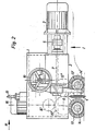
- the gearbox 2 rests on the support frame 1 of the device according to the invention, on the latter Flank is a motor 3 for driving the two circular disk-shaped knives 4, 4 'intended for slitting the cable sheathing.
- a clutch 5 is assigned to the output shaft of this motor 3.
- the motor 3 sets the eccentric shaft 7 of the upper knife 4 coaxial with it, and this upper eccentric shaft 7 is in turn rotationally connected to the lower (7 ') by means of a gear wheel.
- the two knives 4 and 4 ' are non-rotatably supported on the free ends of the pivotable tool carriers 6, 6' which are designed as two-armed levers and which in turn are rotatably supported on the associated eccentric shafts 7, 7 '; in practice the eccentricity can be about 5 mm.
- the ends of the tool carriers 6, 6 'opposite the tools 4, 4' are by means of the links 8, 8 ', the sliders 9, 9' and a setting wheel 10 connected to a spindle and cooperating with screw or worm drives, not shown, the shaft of which is guided in the bearing 11, adjustable relative to one another, in order thereby to be able to set the distance between the two knives 4, 4 'from one another and thus the cutting depth and also the contact pressure of the tools 4, 4' exactly and to vary them as required.
- Spring assemblies are to be arranged in the sliders 9, 9 ', by means of which the contact pressure can be limited upwards in order to rule out knife damage caused by excessive stress. A preload to be set during assembly must be maintained during operation so that the block length of the spring assemblies can never be achieved even with large clippings.
- the tool carriers 6, 6' mounted on the eccentric shafts 7, 7 ' are therefore guided parallel to the carrier axis, that is to say parallel to the feed direction.
- the cable 12, the sheath of which is to be slit open by means of the knives 4, 4 ', is - as shown in FIG. 1 - carried out between these two knives 4, 4', which are adjustable relative to one another, its feed movement being effected by the movements of the two knives receives non-rotatably supporting tool carrier 6, 6 '.
- the ends of the tool carriers 6, 6 'carrying these knives 4,4' carry out the following movements in approximately elliptical paths as a result of the drive by the eccentric shafts 7, 7 ', with a knife stroke of approximately a vertical movement of 20 mm and a horizontal movement of 10 mm corresponds.
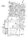
- a pair of feed wheels 13, 13 ' is additionally provided to ensure that the feed movement of the cable 12 takes place at a speed of about 7 m / s and to center it , 14 'are set in rotation by the drive motor 16 via a gear transmission.
- This transmission is housed within the support frame 1, whereas the drive shafts 14, 14 'of the feed wheels 13 are mounted outside of this support frame 1 on its flank in bearings 17, 17'.
- the distance between the drive shafts 14, 14 'from one another can be adjusted, specifically by means of a spindle drive 18 (FIG. 3) and an associated crank 19, which is mounted on the flank of the support frame 1 opposite the bearings 17, 17'.
- the drive shafts 14 and 14 'of the feed wheels 13, 13' are driven via their drive rings 15 and 15 ', which are arranged at the lower end and which, in turn, are meshed with one another at the lower ends by gear shafts 14 "arranged gears 15" are rotated by the output 16 'of the motor 16. Thanks to this gear design, the distance of the drive shafts 14, 14 'from one another can be varied by pivoting these shafts in the horizontal plane.
- a spring must also be arranged in the spindle drive 18 in order to limit the contact pressure upwards and thereby prevent the risk of excessive stress on the machine parts.
- the feed path of the tools with the eccentric drive is expediently to be dimensioned somewhat less than their cutting length; the result is that the cut lengths overlap a little.
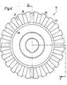
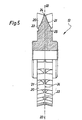
- the individual feed wheel 13 shown in FIGS. 4 and 5 is profiled on its wheel rim with transverse ribs 20 which are designed to protrude sideways and radially on the two flanks 21 of the ridge 23 running in the central plane 22.
- This ridge 23 has a blunt edge 24, and the transverse ribs 20 attached to the flanks 21 protrude radially from this edge 24.
- a groove 25 runs on both sides in each side surface of the feed wheel 13.
- the distances between the circular disk-shaped knives 4, 4 'and the feed wheels 13, 13' are set to the desired dimension and then the clippings, for example the cable 12, are inserted between the knives and feed wheels, after which they are switched on motors 3 and 16 use the automatic feed movement.
- Curved cables must be routed so that the plane of curvature is vertical and the curved end is up, so that the interface is fed horizontally to the knives.
Landscapes
- Removal Of Insulation Or Armoring From Wires Or Cables (AREA)
Claims (10)
Applications Claiming Priority (2)
| Application Number | Priority Date | Filing Date | Title |
|---|---|---|---|
| AT3424/82 | 1982-09-13 | ||
| AT342482A AT379476B (de) | 1982-09-13 | 1982-09-13 | Vorrichtung zum vorschub und gegebenenfalls zur bearbeitung eines fortlaufend gefoerderten stranges |
Publications (3)
| Publication Number | Publication Date |
|---|---|
| EP0106836A2 EP0106836A2 (fr) | 1984-04-25 |
| EP0106836A3 EP0106836A3 (en) | 1984-07-25 |
| EP0106836B1 true EP0106836B1 (fr) | 1987-05-20 |
Family
ID=3550309
Family Applications (1)
| Application Number | Title | Priority Date | Filing Date |
|---|---|---|---|
| EP19830890160 Expired EP0106836B1 (fr) | 1982-09-13 | 1983-09-13 | Dispositif pour l'avancement et/ou pour l'usinage d'une corde transportée continuellement |
Country Status (3)
| Country | Link |
|---|---|
| EP (1) | EP0106836B1 (fr) |
| AT (1) | AT379476B (fr) |
| DE (1) | DE3371722D1 (fr) |
Families Citing this family (1)
| Publication number | Priority date | Publication date | Assignee | Title |
|---|---|---|---|---|
| FR2729590B1 (fr) * | 1995-01-23 | 1997-03-28 | Morana Benito | Dispositif de nettoyage de la surface externe d'elements longilignes cylindriques, notamment de cables |
Family Cites Families (4)
| Publication number | Priority date | Publication date | Assignee | Title |
|---|---|---|---|---|
| US2319198A (en) * | 1940-09-24 | 1943-05-18 | Western Electric Co | Apparatus for slitting and cutting conductors |
| DE962717C (de) * | 1952-03-19 | 1957-04-25 | Carl Sauer | Verfahren und Vorrichtung zum kontinuierlichen Aufschneiden oder Aufschlitzen der elastischen Umhuellung von Kabeln, Litzen u. dgl. |
| US3030694A (en) * | 1956-01-30 | 1962-04-24 | Amp Inc | Lead making apparatus and method |
| US3724310A (en) * | 1971-06-18 | 1973-04-03 | Impact Ind Holdings Ltd | Cable splitter |
-
1982
- 1982-09-13 AT AT342482A patent/AT379476B/de not_active IP Right Cessation
-
1983
- 1983-09-13 DE DE8383890160T patent/DE3371722D1/de not_active Expired
- 1983-09-13 EP EP19830890160 patent/EP0106836B1/fr not_active Expired
Also Published As
| Publication number | Publication date |
|---|---|
| AT379476B (de) | 1986-01-10 |
| DE3371722D1 (en) | 1987-06-25 |
| ATA342482A (de) | 1985-05-15 |
| EP0106836A3 (en) | 1984-07-25 |
| EP0106836A2 (fr) | 1984-04-25 |
Similar Documents
| Publication | Publication Date | Title |
|---|---|---|
| DE69203508T2 (de) | Maschine zum Schneiden von Materialbahnrollen. | |
| DE1582361C3 (de) | Maiserntemaschine | |
| DE2602262A1 (de) | Kantenschneidmaschine fuer das abkanten von topffoermigen, metallenen werkstuecken, wie dosenruempfe u.dgl. | |
| DE2320706A1 (de) | Futtererntemaschine | |
| EP0390939A1 (fr) | Machine pour couper verticalement selon des contours | |
| DE3736002C2 (fr) | ||
| DE202013004505U1 (de) | Werkstückübergabeeinrichtung | |
| DE3418030A1 (de) | Kettenzahnrad mit radialer reinigung | |
| DE3123183C2 (fr) | ||
| DE2941293C2 (fr) | ||
| DE69803238T2 (de) | Abrichtmaschine | |
| DE1935414A1 (de) | Vorrichtung zum Entasten von Baeumen | |
| DE69430379T2 (de) | Draht-und kabelverarbeitungssystem | |
| DE2134012A1 (de) | Beschickungsvorrichtung für Furniermessermaschinen | |
| AT396666B (de) | Längskreissäge zum zuschneiden von in etwa horizontaler ebene angeordnetem plattengut | |
| EP0106836A2 (fr) | Dispositif pour l'avancement et/ou pour l'usinage d'une corde transportée continuellement | |
| EP0477166B1 (fr) | Machine pour enlever les renflements de la partie inférieure du trone d'un arbre | |
| DE2752648A1 (de) | Vorrichtung zum schneiden einer einfuehrungsspitze an warenbahnen | |
| DE2823737C2 (de) | Vorrichtung zum fortlaufenden Lochen der Wandung dünnwandiger gewellter Rohre, insbesondere Dränrohre | |
| DE3128703A1 (de) | "maschine zum entgraten von blechen od.dgl." | |
| DE3040447C1 (de) | Rollentisch fuer Blechbearbeitungsmaschinen | |
| DE3331905C2 (de) | Laserstrahlbearbeitungsmaschine | |
| DE3006832C2 (de) | Maschine zum Entgraten | |
| DE2712204C2 (de) | Gerät zum Entnehmen von Futterportionen aus Silos | |
| DE19933295B4 (de) | Mit einem Antrieb versehene Vorrichtung zur Durchführung von Bearbeitungsvorgängen an einer oder mehreren Schichten von tuchförmigem Arbeitsmaterial |
Legal Events
| Date | Code | Title | Description |
|---|---|---|---|
| PUAI | Public reference made under article 153(3) epc to a published international application that has entered the european phase |
Free format text: ORIGINAL CODE: 0009012 |
|
| AK | Designated contracting states |
Designated state(s): BE CH DE FR GB IT LI LU NL SE |
|
| PUAL | Search report despatched |
Free format text: ORIGINAL CODE: 0009013 |
|
| AK | Designated contracting states |
Designated state(s): BE CH DE FR GB IT LI LU NL SE |
|
| 17P | Request for examination filed |
Effective date: 19850125 |
|
| 17Q | First examination report despatched |
Effective date: 19860409 |
|
| ITF | It: translation for a ep patent filed | ||
| GRAA | (expected) grant |
Free format text: ORIGINAL CODE: 0009210 |
|
| AK | Designated contracting states |
Kind code of ref document: B1 Designated state(s): BE CH DE FR GB IT LI LU NL SE |
|
| ET | Fr: translation filed | ||
| REF | Corresponds to: |
Ref document number: 3371722 Country of ref document: DE Date of ref document: 19870625 |
|
| PG25 | Lapsed in a contracting state [announced via postgrant information from national office to epo] |
Ref country code: LU Free format text: LAPSE BECAUSE OF NON-PAYMENT OF DUE FEES Effective date: 19870930 |
|
| PGFP | Annual fee paid to national office [announced via postgrant information from national office to epo] |
Ref country code: NL Payment date: 19870930 Year of fee payment: 5 |
|
| PLBE | No opposition filed within time limit |
Free format text: ORIGINAL CODE: 0009261 |
|
| STAA | Information on the status of an ep patent application or granted ep patent |
Free format text: STATUS: NO OPPOSITION FILED WITHIN TIME LIMIT |
|
| 26N | No opposition filed | ||
| PG25 | Lapsed in a contracting state [announced via postgrant information from national office to epo] |
Ref country code: GB Effective date: 19890913 |
|
| PG25 | Lapsed in a contracting state [announced via postgrant information from national office to epo] |
Ref country code: SE Effective date: 19890914 |
|
| PG25 | Lapsed in a contracting state [announced via postgrant information from national office to epo] |
Ref country code: LI Effective date: 19890930 Ref country code: CH Effective date: 19890930 Ref country code: BE Effective date: 19890930 |
|
| BERE | Be: lapsed |
Owner name: FONDAMET J. & M. JANU K.G. Effective date: 19890930 |
|
| PG25 | Lapsed in a contracting state [announced via postgrant information from national office to epo] |
Ref country code: NL Effective date: 19900401 |
|
| GBPC | Gb: european patent ceased through non-payment of renewal fee | ||
| NLV4 | Nl: lapsed or anulled due to non-payment of the annual fee | ||
| PG25 | Lapsed in a contracting state [announced via postgrant information from national office to epo] |
Ref country code: FR Effective date: 19900531 |
|
| REG | Reference to a national code |
Ref country code: CH Ref legal event code: PL |
|
| PG25 | Lapsed in a contracting state [announced via postgrant information from national office to epo] |
Ref country code: DE Effective date: 19900601 |
|
| REG | Reference to a national code |
Ref country code: FR Ref legal event code: ST |
|
| EUG | Se: european patent has lapsed |
Ref document number: 83890160.1 Effective date: 19900521 |