EP0107056A2 - Trancheuse - Google Patents
Trancheuse Download PDFInfo
- Publication number
- EP0107056A2 EP0107056A2 EP83109502A EP83109502A EP0107056A2 EP 0107056 A2 EP0107056 A2 EP 0107056A2 EP 83109502 A EP83109502 A EP 83109502A EP 83109502 A EP83109502 A EP 83109502A EP 0107056 A2 EP0107056 A2 EP 0107056A2
- Authority
- EP
- European Patent Office
- Prior art keywords
- conveyor belt
- machine according
- cutting
- bar
- cut
- Prior art date
- Legal status (The legal status is an assumption and is not a legal conclusion. Google has not performed a legal analysis and makes no representation as to the accuracy of the status listed.)
- Ceased
Links
Images


Classifications
-
- B—PERFORMING OPERATIONS; TRANSPORTING
- B26—HAND CUTTING TOOLS; CUTTING; SEVERING
- B26D—CUTTING; DETAILS COMMON TO MACHINES FOR PERFORATING, PUNCHING, CUTTING-OUT, STAMPING-OUT OR SEVERING
- B26D7/00—Details of apparatus for cutting, cutting-out, stamping-out, punching, perforating, or severing by means other than cutting
- B26D7/27—Means for performing other operations combined with cutting
- B26D7/32—Means for performing other operations combined with cutting for conveying or stacking cut product
- B26D7/325—Means for performing other operations combined with cutting for conveying or stacking cut product stacking the cut product individually separated by separator elements
-
- B—PERFORMING OPERATIONS; TRANSPORTING
- B26—HAND CUTTING TOOLS; CUTTING; SEVERING
- B26D—CUTTING; DETAILS COMMON TO MACHINES FOR PERFORATING, PUNCHING, CUTTING-OUT, STAMPING-OUT OR SEVERING
- B26D7/00—Details of apparatus for cutting, cutting-out, stamping-out, punching, perforating, or severing by means other than cutting
- B26D7/01—Means for holding or positioning work
-
- B—PERFORMING OPERATIONS; TRANSPORTING
- B26—HAND CUTTING TOOLS; CUTTING; SEVERING
- B26D—CUTTING; DETAILS COMMON TO MACHINES FOR PERFORATING, PUNCHING, CUTTING-OUT, STAMPING-OUT OR SEVERING
- B26D7/00—Details of apparatus for cutting, cutting-out, stamping-out, punching, perforating, or severing by means other than cutting
- B26D7/06—Arrangements for feeding or delivering work of other than sheet, web, or filamentary form
- B26D7/0608—Arrangements for feeding or delivering work of other than sheet, web, or filamentary form by pushers
-
- B—PERFORMING OPERATIONS; TRANSPORTING
- B26—HAND CUTTING TOOLS; CUTTING; SEVERING
- B26D—CUTTING; DETAILS COMMON TO MACHINES FOR PERFORATING, PUNCHING, CUTTING-OUT, STAMPING-OUT OR SEVERING
- B26D7/00—Details of apparatus for cutting, cutting-out, stamping-out, punching, perforating, or severing by means other than cutting
- B26D7/01—Means for holding or positioning work
- B26D2007/011—Means for holding or positioning work by clamping claws, e.g. in high speed slicers for food products
-
- Y—GENERAL TAGGING OF NEW TECHNOLOGICAL DEVELOPMENTS; GENERAL TAGGING OF CROSS-SECTIONAL TECHNOLOGIES SPANNING OVER SEVERAL SECTIONS OF THE IPC; TECHNICAL SUBJECTS COVERED BY FORMER USPC CROSS-REFERENCE ART COLLECTIONS [XRACs] AND DIGESTS
- Y10—TECHNICAL SUBJECTS COVERED BY FORMER USPC
- Y10T—TECHNICAL SUBJECTS COVERED BY FORMER US CLASSIFICATION
- Y10T83/00—Cutting
- Y10T83/202—With product handling means
- Y10T83/2033—Including means to form or hold pile of product pieces
- Y10T83/2037—In stacked or packed relation
- Y10T83/2046—Including means to move stack bodily
-
- Y—GENERAL TAGGING OF NEW TECHNOLOGICAL DEVELOPMENTS; GENERAL TAGGING OF CROSS-SECTIONAL TECHNOLOGIES SPANNING OVER SEVERAL SECTIONS OF THE IPC; TECHNICAL SUBJECTS COVERED BY FORMER USPC CROSS-REFERENCE ART COLLECTIONS [XRACs] AND DIGESTS
- Y10—TECHNICAL SUBJECTS COVERED BY FORMER USPC
- Y10T—TECHNICAL SUBJECTS COVERED BY FORMER US CLASSIFICATION
- Y10T83/00—Cutting
- Y10T83/444—Tool engages work during dwell of intermittent workfeed
- Y10T83/463—Work-feed element contacts and moves with work
- Y10T83/4632—Comprises a work-moving gripper
-
- Y—GENERAL TAGGING OF NEW TECHNOLOGICAL DEVELOPMENTS; GENERAL TAGGING OF CROSS-SECTIONAL TECHNOLOGIES SPANNING OVER SEVERAL SECTIONS OF THE IPC; TECHNICAL SUBJECTS COVERED BY FORMER USPC CROSS-REFERENCE ART COLLECTIONS [XRACs] AND DIGESTS
- Y10—TECHNICAL SUBJECTS COVERED BY FORMER USPC
- Y10T—TECHNICAL SUBJECTS COVERED BY FORMER US CLASSIFICATION
- Y10T83/00—Cutting
- Y10T83/647—With means to convey work relative to tool station
- Y10T83/654—With work-constraining means on work conveyor [i.e., "work-carrier"]
-
- Y—GENERAL TAGGING OF NEW TECHNOLOGICAL DEVELOPMENTS; GENERAL TAGGING OF CROSS-SECTIONAL TECHNOLOGIES SPANNING OVER SEVERAL SECTIONS OF THE IPC; TECHNICAL SUBJECTS COVERED BY FORMER USPC CROSS-REFERENCE ART COLLECTIONS [XRACs] AND DIGESTS
- Y10—TECHNICAL SUBJECTS COVERED BY FORMER USPC
- Y10T—TECHNICAL SUBJECTS COVERED BY FORMER US CLASSIFICATION
- Y10T83/00—Cutting
- Y10T83/647—With means to convey work relative to tool station
- Y10T83/6571—With means to store work articles
Definitions
- the invention relates to a machine for cutting cuttings bars, such as cheese and sausage bars or the like, with a transport device which supports the cuttings bar and intermittently moves forward by the thickness of the cut slices and is inclined to the horizontal and which consists of a conveyor belt supporting the cuttings bar and this one its rear end holding claw device, and in front of its front end a circular knife mounted in an eccentric is arranged, which moves the circular knife driven at a higher speed than it in the cutting cycle transversely to the direction of transport of the product bar over its cross-sectional area.
- a transport device which supports the cuttings bar and intermittently moves forward by the thickness of the cut slices and is inclined to the horizontal and which consists of a conveyor belt supporting the cuttings bar and this one its rear end holding claw device, and in front of its front end a circular knife mounted in an eccentric is arranged, which moves the circular knife driven at a higher speed than it in the cutting cycle transversely to the direction of transport of the product bar over its cross-sectional area.
- the object of the invention is therefore to provide a machine of the type specified at the outset, with which cut goods bars can be cut into slices with increased performance and with reduced friction.
- this object is achieved in that the conveyor belt runs over freely rotatable deflection rollers and on both sides of the conveyor belt parallel to the upper run above which movable claw devices are arranged, the gripping claws of which are fastened to mutually parallel shafts provided with swivel drives, which are transverse to the direction of advance the upper run extendable and retractable from its area are mounted in support pieces which are provided with drives for gradual feed and with fast feed and return gears, and that a collecting device for the cut slices is arranged below the front end of the conveyor belt.
- the clippings bar supported at an angle on the conveyor belt is held by the claw device and is advanced by the intermittent drive of the claw device by a distance corresponding to the disk thickness into the cutting plane.
- the respective disc thickness corresponds very precisely to the gradual advance of the claw device. Since no pressure is exerted on the circular knife from the outer cut surface during the cutting off of the discs, the cutting of the discs takes place with the least possible friction. The disks can therefore be removed at a very high speed.
- claw devices are provided on both sides of the conveyor belt with retractable and retractable gripping claws, the other claw device can already hold the following cut goods bar in a standby position during the cutting of a cut product bar, so that it can be moved into its cut position via the fast feed gear after the end of the Gripping claws holding the previous cutter bar have been laterally withdrawn from the area of the conveyor belt.
- the gripping claws holding the end of the product to be cut can now be moved in the desired manner - and after removing the end of the product to be cut they can pick up the next product to be cut and keep it in the ready position.
- the machine according to the invention thus enables very high cutting performance due to its tandem design.
- the support pieces of the claw devices which are arranged on both sides next to the conveyor belt, are expediently each provided with a spindle nut arranged on their outer sides and are supported on their sides facing the conveyor belt on rails running parallel to the latter, with spindles running parallel to the rails being screwed into the spindle nuts, which can be driven by drives arranged at the head. Thanks to the spindle drives, the claw devices can be moved step-by-step or at high speed in a favorable manner.
- the support pieces of the claw devices are each provided with a pair of pliers-like clamping devices, the jaws of which each have the edge region of the upper run of the conveyor belt frame and can be coupled to the upper run for transport.
- This configuration ensures that the intermittent feed movement is simultaneously transferred from the claw devices to the cutting bar and the conveyor belt at the same time, which favors the cutting of disks of the same thickness.
- the claw devices can be provided with two shafts carrying the upper claws, which can optionally be pivoted against the shaft opposite to the shaft carrying the lower claws. In this way, cuttings of different heights can be easily clamped into the claw devices.
- a roller track or the like is pivotally mounted in the frame, which has a swiveling front stop and by a pressure-piston-cylinder unit or the like from a below the conveyor plane of the conveyor belt available standby position is pivotable in the conveyor level.
- the roller conveyor In its standby position, the roller conveyor is approximately in a horizontal position, so that the clippings bar to be cut next can be placed on this. Now the roller conveyor in the conveying plane of the conveyor belt feed path of the claw device moved behind it, so that after the corresponding ancestor the rear end of this cut bar can be clamped in a simple manner in the gripping claws.
- the claw device is expediently in its retracted position above the roller conveyor pivoted into its approximately horizontal standby position, so that after the gripping claws have been opened, the clippings are cut onto the roller conveyor falls and can easily be lifted off.
- the collecting device for the cut slices expediently consists of a conveyor device formed from endless belts which run parallel to one another around end-side rollers or rollers.
- This conveying device can be driven to remove it after the formation of a stack, or it can be driven continuously if it is desired to store the cut slices in an overlapping manner.
- two rake-like gratings which can be pivoted parallel to themselves and alternate with one another, the cantilevered prongs of which they are lowerable from their stack position located above the upper strands of the belts and are additionally designed to be retractable and retractable.
- These grids are used to form stacks from cut disks, and after forming a stack of the desired height, they are lowered between the belts of the conveying device in such a way that the stack is placed on the conveying device.
- the respective grate in its stacking position can expediently be lowered in accordance with the increasing stack height, so that the cut-off slices always have to overcome the same drop height and an exact stack formation is ensured.
- a paper web feed device is arranged below the conveyor belt, the substantially horizontal feed plane of which lies in the region of the lower edge of the cut bar in its cutting position and which intermittently the front free end of a paper web is in each case about one slice width over the last cut Disc pushes.
- the respective front end is located in the area of the lower front edge of the clippings bar, so that at the same time as the slices of clippings are cut, the slips which later serve to separate the slices are also separated from the paper web.
- a clean position of the separated pieces of paper is favored by the fact that a blowing air nozzle blowing the front forward end of the paper web against the cut surface of the bar is provided.
- a pressure roller which can be lowered onto the cut goods bar can be provided in the region above the lower deflection roller of the conveyor belt.
- the roller or rollers that advance the paper web are driven by a gear mechanism that includes a differential gear, the third input of which is rotated back and forth in the cutting cycle by a crank mechanism through a connecting rod.
- the stroke of the crank mechanism can be designed in such a way that after the paper web has been fed and the slip separated, the paper web is pulled back a little, which favors the trouble-free advancement again.
- the differential is expediently a bevel gear differential, the housing of which the differential bevel gears are mounted is rotated back and forth by the crank mechanism.
- a gear with a clutch-brake combination is provided for the intermittent drive of the spindles for the claw devices, in which the release of the output shaft and coupling to the intermittent drive by one of one Crank drive operated trapezoidal thread and the intermittent drive is carried out by another crank drive.
- the eccentricity of the crank drive for the intermittent drive of the spindles can expediently be adjusted via a planetary gear differential, which radially shifts the crankshaft bearing relative to the gear drive shaft via a face gear.
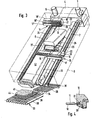
- the cheese slicer has a machine frame 1, which consists of a base frame part 2 and a frame-shaped frame part 3 supported obliquely on this.
- the frame-shaped frame part 3 carries at its head end a gear box 4 with flanged electric motors 5, 6, which contains the drive devices for the spindles 7, 8 which run parallel to one another.
- the upper ends of the spindles 7, 8 are mounted in the gearbox 4, while the lower ends of the spindles 7, 8 are mounted in a lower cross piece, not shown, which is arranged at the lower end of the frame part 3.
- rollers 9, 10 are freely rotatably supported, over which the endless conveyor belt 11 provided with a profile runs on its upper side.
- the conveyor belt 11 is profiled only in its central region and, as can be seen from FIG. 4, is reinforced with longitudinal steel inserts 12.
- claw devices 13, 14 are arranged in mirror image to each other, which consist of support pieces 15, 15 ', in which gripping claw shafts 16, 16' and supporting plates 17, 18, 17 ', 18' are displaceably guided.
- the upward-facing gripping claws 19 are attached in a comb-like manner on a lower gripping-claw shaft, while the opposite-facing gripping-claws 20, 21 are arranged in a comb-like manner on two upper gripping-claw shafts arranged one above the other in parallel.
- the support strips 17, 18, 17 ', 18' are driven back and forth by drive means, not shown.
- the gripping claw shafts also have these reciprocating drives and additional swivel drives, which consist of pneumatic pressure-piston-cylinder units.
- a roller track 26 is pivotally mounted about an axis 25 fastened in the frame and is provided at its front end with a stop 27 which can be swiveled in and out.
- the roller track 26 is articulated on the piston rod of a pneumatic cylinder 28 which is articulated in the machine frame.
- the roller track 26 is provided with a further pneumatic cylinder 29 for pivoting in and pivoting out the stop plate 27.
- the support pieces 15, 15 ' have on their side facing the conveyor belt 11 a pivotable clamping jaw 30 which cooperates with an abutment 31 of the support pieces.
- a pivotable clamping jaw 30 which cooperates with an abutment 31 of the support pieces.
- a conveyor device 33 consisting of endless belts running at a distance parallel to one another is arranged below the working area of the rotating circular knife 32, which is guided by an eccentric over the cutting area. Furthermore, two gratings 34, 35, which are moved by a mechanism (not shown) and have freely projecting tines 36, are provided, which can be moved in parallel parallel to themselves under the working area of the circular knife above the conveyor device 33 and with their tines into the spaces between the endless belts 38 Conveyor 33 can be lowered.
- the gratings 34, 35 serve to form stacks from the cut slices and can be lowered in accordance with the increasing stack height.
- the disk packs are placed on the endless belts 38 of the conveyor 33. During the removal of the last stack, the other grate can already be retracted over it, so that the stacking does not interrupt the cutting operation.
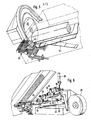
- a feed device consisting of rollers is provided for a paper web 40 drawn off from a supply roll 39, which is intermittently advanced by about one slice width each over the last cut slice 41.
- the paper web 40 is preferred by pairs of rollers arranged in the manner of a rocker, which interact with counter-rollers, as are known in their basic structure from DE-OS 22 52 605.
- the approximately horizontal feed plane of the paper web touches the cut goods bar 42 to be cut at its lower edge region, so that a piece of paper 43 is separated from the paper web together with the disk and falls onto the stack 44 together with the cut disk.
- blowing nozzle Below the front end of the advanced paper web 40 is a blowing nozzle, not shown, which is the front 3 presses against the front cut surface of the last separated disc in the manner shown in FIG.
- the feed device for the paper web 40 consists of two rollers 47, 48 and 49, 50 which are freely rotatably mounted in a rocker 45, 46 and which each cooperate with counter-rollers, by which the rollers 51, 52 are driven.
- the preferred device with the rocker 46 is used to form a supply loop in the paper web 40, which is pulled out by the spring-loaded pendulum roller 53. After lowering the pressure roller 48, the driven roller 51 then intermittently advances the web by one slip width from this supply loop.
- the pivoting of the rockers carrying the rollers is carried out in the manner known from DE-OS 22 52 605 by pneumatic cylinders.
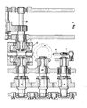
- the transmission driving the preferred roller 51 is explained in more detail below with reference to FIG. 7.
- the drive shaft 54 drives spur gear pairs which are arranged parallel to the latter. Waves 55, 56 on.
- the shaft 55 forms the input shaft of the bevel gear differential 57, the output shaft 58 of which is aligned with the latter and is in drive connection with the paper feed roller 51.
- the shaft 56 is provided with an eccentric crank pin 59, on which the connecting rod 60 is mounted, which is articulated on the cage 61 of the bevel gear differential gear 57 and sets it in an oscillating reciprocating motion.
- This pendulum movement corresponds to the machine cycle due to the selected translations and has an amplitude that corresponds to the desired intermittent feed of the paper web.
- the pressure roller 48 is lifted off the feed roller 51 and the paper web is clamped by the roller 47.
- the gear for the intermittent feed drive of the spindles 7, 8 is explained in more detail below with reference to FIG. 8.
- two ball bearings 63, 64 are wedged on the drive shaft 62, which together with the connecting rods 65, 66 each form crank drives.
- the clutch / brake combination 78 has a clutch actuator 79, which is provided with an internally conical clutch surface and is connected to the output shaft 57 in a rotationally locking manner. Relative to the output shaft 57, the clutch actuator 78 is axially displaceably guided on the axial driving pins 80 and is loaded by compression springs 81. In the braking position, the compression springs 81 press the clutch actuator 79 with its conical outer ring against the inner conical brake ring 82.
- the connecting rod 66 drives the drive sleeve 84, which is rotatably mounted on the output shaft 77, to oscillate back and forth via the eccentric bolt 83.
- the drive sleeve 84 is provided with axially extending bolts 85, on which the coupling sleeve 86 is axially displaceably guided.
- the coupling sleeve 86 is freely rotatable, but axially immovably connected to the switching sleeve 87.
- the switching sleeve 87 is in a three common trapezoidal thread 88 of the control sleeve 89 is screwed in, which is freely rotatable via the needle bearing, but is axially immovable on the drive sleeve 84.
- the control sleeve 89 is provided with an eccentric pin 90 on which the connecting rod 65 is mounted.
- the control sleeve 89 is thus set in an oscillating movement in the machine cycle, so that the clutch actuator 79 is lifted from the clutch sleeve 86 by the brake ring 82 in the machine cycle and is coupled to the drive sleeve 84.
- the stroke of the crank mechanism 64, 66 can be changed in accordance with the desired intermittent feed movement.
- the sun gear 92 of a planetary planetary gear 91 is keyed onto the drive shaft 62, which transmits the drive speed to the output sleeve 93, which is supported on the drive shaft 62 via needle bearings, when the planet gear web 94 is at rest, so that the drive shaft 62 and the output sleeve 93 rotate at the same speed.
- a wheel 95 with helical trapezoidal toothing on the end is wedged onto the output sleeve 93.
- the trapezoidal toothing meshes with a toothed block 96 which is fixedly connected to the ring carrying the ball bearing 64 and is guided in a radial guide 97 of the disk 98 which is wedged onto the drive shaft 62.
- An additional rotary movement can be fed into the planet gear web 94 of the planetary planetary gear train 91 via a worm gear drive 99, so that the disk 64 can be rotated to adjust the eccentricity of the crank drive 64, 66.
- the intermittent feed gear for the spindles 7, 8 is designed such that a rotation movement of 25% with increasing sinusoidal acceleration, 25% falling sinusoidal deceleration and subsequent 50% standstill is transmitted via the clutch brake combination 78 per revolution of the crank mechanism 64, 66.
Landscapes
- Life Sciences & Earth Sciences (AREA)
- Forests & Forestry (AREA)
- Engineering & Computer Science (AREA)
- Mechanical Engineering (AREA)
- Nonmetal Cutting Devices (AREA)
- Details Of Cutting Devices (AREA)
- Delivering By Means Of Belts And Rollers (AREA)
- Formation And Processing Of Food Products (AREA)
- Specific Conveyance Elements (AREA)
- Preliminary Treatment Of Fibers (AREA)
Applications Claiming Priority (2)
| Application Number | Priority Date | Filing Date | Title |
|---|---|---|---|
| DE19823239178 DE3239178A1 (de) | 1982-10-22 | 1982-10-22 | Maschine zum schneiden von schneidgutriegeln |
| DE3239178 | 1982-10-22 |
Related Child Applications (2)
| Application Number | Title | Priority Date | Filing Date |
|---|---|---|---|
| EP87110173A Division EP0251337B1 (fr) | 1982-10-22 | 1983-09-23 | Mécanisme d'alimentation de papier pour trancheuse |
| EP87110173.9 Division-Into | 1983-09-23 |
Publications (2)
| Publication Number | Publication Date |
|---|---|
| EP0107056A2 true EP0107056A2 (fr) | 1984-05-02 |
| EP0107056A3 EP0107056A3 (fr) | 1986-07-16 |
Family
ID=6176370
Family Applications (2)
| Application Number | Title | Priority Date | Filing Date |
|---|---|---|---|
| EP83109502A Ceased EP0107056A3 (fr) | 1982-10-22 | 1983-09-23 | Trancheuse |
| EP87110173A Expired - Lifetime EP0251337B1 (fr) | 1982-10-22 | 1983-09-23 | Mécanisme d'alimentation de papier pour trancheuse |
Family Applications After (1)
| Application Number | Title | Priority Date | Filing Date |
|---|---|---|---|
| EP87110173A Expired - Lifetime EP0251337B1 (fr) | 1982-10-22 | 1983-09-23 | Mécanisme d'alimentation de papier pour trancheuse |
Country Status (6)
| Country | Link |
|---|---|
| US (2) | US4583435A (fr) |
| EP (2) | EP0107056A3 (fr) |
| JP (1) | JPS5993297A (fr) |
| AT (1) | AT394153B (fr) |
| DE (1) | DE3239178A1 (fr) |
| DK (1) | DK485283A (fr) |
Cited By (11)
| Publication number | Priority date | Publication date | Assignee | Title |
|---|---|---|---|---|
| DE3912445A1 (de) * | 1989-04-15 | 1990-10-18 | Dixie Union Verpackungen Gmbh | Vorrichtung an schneidmaschinen zum aufschneiden, z.b. von lebensmitteln |
| WO1991007097A1 (fr) * | 1989-11-14 | 1991-05-30 | Robert Beasant | Trancheuse |
| DE10045055A1 (de) * | 2000-09-12 | 2002-03-21 | Biforce Anstalt Vaduz | Aufschneide- und Weitertransportvorrichtung für Lebensmittelprodukte |
| DE10353114A1 (de) * | 2003-10-15 | 2005-05-12 | Cfs Kempten Gmbh | Verfahren und Vorrichtung zum Aufschneiden von Lebensmittelriegeln |
| KR100851796B1 (ko) * | 2002-10-31 | 2008-08-13 | 산드빅 인터렉츄얼 프로퍼티 에이비 | 칩형성 기계가공용의 인덱서블 선삭 공구 |
| DE102008019776A1 (de) | 2008-04-18 | 2009-10-22 | CFS Bühl GmbH | Verfahren, Vorrichtung sowie Messer zum Aufschneiden von Lebensmitteln |
| DE102009044048A1 (de) * | 2009-09-18 | 2011-03-24 | Reifenhäuser, Uwe, Dipl.-Ing. | Verfahren und Vorrichtung zum Schneiden eines Lebensmittelstrangs in Scheiben |
| DE102010027126A1 (de) * | 2010-07-14 | 2012-01-19 | Weber Maschinenbau Gmbh Breidenbach | Vorrichtung und Verfahren zum Aufschneiden von Lebensmittelprodukten |
| EP1704973B2 (fr) † | 2005-03-22 | 2012-04-11 | Uwe Reifenhäuser | Méthode et appareil pour couper des produits alimentaires allongés |
| EP2599598A2 (fr) | 2011-11-30 | 2013-06-05 | GEA CFS Bühl GmbH | Procédé de coupe d'une barre de produit alimentation en utilisant un capteur de vibrations |
| US9597812B2 (en) | 2012-04-30 | 2017-03-21 | Gea Food Solutions Germany Gmbh | Slicing device comprising a product gripper |
Families Citing this family (61)
| Publication number | Priority date | Publication date | Assignee | Title |
|---|---|---|---|---|
| DE3249925C2 (en) * | 1982-10-22 | 1990-06-13 | Natec Reich, Summer Gmbh & Co Kg, 8999 Heimenkirch, De | Device for cutting blocks of material to be cut, such as blocks of cheese and sausage meat or the like |
| DE3239178A1 (de) | 1982-10-22 | 1984-04-26 | Natec Reich, Summer GmbH & Co KG, 8999 Heimenkirch | Maschine zum schneiden von schneidgutriegeln |
| DE3608780C2 (de) * | 1986-03-15 | 1995-08-17 | Ernst Holz | Vorrichtung zum Schneiden von Lebensmitteln |
| JPH01164596A (ja) * | 1987-12-18 | 1989-06-28 | Kunio Yoshida | 薄切り片間への密着防止片装着装置 |
| GB2222970B (en) * | 1988-08-03 | 1993-04-14 | Amada Co Ltd | Machine tool |
| JPH02198796A (ja) * | 1989-01-25 | 1990-08-07 | Oda Shoji Kk | スライス装置 |
| JPH0611477B2 (ja) * | 1989-03-23 | 1994-02-16 | 吉田 好枝 | 薄切り片間への密着防止片装着装置 |
| US5125305A (en) * | 1990-09-13 | 1992-06-30 | General Mills, Inc. | Apparatus and method for cutting slabs from a frozen fish block |
| DE9104580U1 (de) * | 1991-04-16 | 1992-06-17 | Natec Reich, Summer GmbH & Co KG, 8996 Opfenbach | Zwischenlage-Apparat zur Einbringung von folienartigem Material in die von einer Schneidemaschine geschnittenenen Scheiben |
| DE9104588U1 (de) * | 1991-04-16 | 1991-10-17 | Natec Reich, Summer GmbH & Co KG, 8996 Opfenbach | Vorschubantrieb für eine Schneidemaschine zum Schneiden von Lebensmittelprodukten |
| US5339945A (en) * | 1992-12-24 | 1994-08-23 | General Mills, Inc. | Indexing device for a gravity log-feeding system |
| GB9312331D0 (en) * | 1993-06-15 | 1993-07-28 | Pj Contracts Limited | Meat substitute manufacturing process |
| ES2114373B1 (es) * | 1994-05-04 | 1999-01-01 | Garcia Torres Ramon | Maquina para la preparacion automatica de porciones o lonchas de jamon y queso en disposicion alternada tipo sandwich. |
| US5628237A (en) * | 1994-10-11 | 1997-05-13 | Formax, Inc. | Slicing machine for two or more food loaves |
| US5885642A (en) * | 1996-03-08 | 1999-03-23 | Land O'lakes, Inc. | Process for improved separation of stacked food slices |
| AT404581B (de) * | 1996-12-20 | 1998-12-28 | Kuchler Fritz | Aufschnittschneidemaschine mit verpackungseinrichtung |
| DE19801782A1 (de) * | 1998-01-19 | 1999-07-22 | Alpma Alpenland Masch | Verfahren und Vorrichtung zum Transport eines Gegenstands |
| DE19860296B4 (de) * | 1998-12-18 | 2007-10-11 | Francotyp-Postalia Gmbh | Verfahren und Anordnung zur Steuerung einer dynamischen Waage |
| DE19926461A1 (de) * | 1999-06-10 | 2000-12-14 | Biforce Anstalt Vaduz | Vorrichtung zum Aufschneiden von Lebensmittelprodukten |
| US6248013B1 (en) * | 1999-09-30 | 2001-06-19 | Ak Robins, Llc | Apparatus for processing meat |
| DE10057333A1 (de) * | 2000-11-17 | 2002-05-23 | Cfs Gmbh Kempten | Vorrichtung an Schneidmaschinen |
| US6655248B1 (en) | 2001-08-30 | 2003-12-02 | Charles H. Johnson | Cheese cutting |
| DE10153755A1 (de) * | 2001-10-31 | 2003-05-15 | Weber Maschb Gmbh & Co Kg | Vorrichtung zum Aufschneiden von Lebensmittelprodukten |
| GB0205835D0 (en) * | 2002-03-13 | 2002-04-24 | Aew Thurne Ltd | Improved foodstuff slicing machine |
| GB2386317B (en) * | 2002-03-13 | 2004-02-04 | Aew Eng Co Ltd | Improvements in and relating to slicing machines |
| AT413350B (de) * | 2002-04-26 | 2006-02-15 | Kuchler Fritz | Antrieb für schnittgutwagen auf einer aufschnittschneidemaschine |
| US6935215B2 (en) * | 2002-08-14 | 2005-08-30 | Formax, Inc. | Slicing machine and conveyor system with automatic product width compensation |
| US7270039B2 (en) * | 2002-09-19 | 2007-09-18 | Formax, Inc. | Reload system for slicing machine |
| DE20218439U1 (de) * | 2002-11-27 | 2003-01-30 | Siller, Rudi, 74232 Abstatt | Maschine zum Schneiden von stabförmigen Lebensmitteln |
| EP1445077A1 (fr) * | 2003-02-05 | 2004-08-11 | José Luis Godoy Varo | Machine à trancher à action double et procédé d'utilisation |
| DE10309552A1 (de) * | 2003-03-04 | 2004-09-16 | Cfs Gmbh Kempten | Sinuider Prozessverlauf einer Aufschnittschneidemaschine |
| DE10353527A1 (de) * | 2003-11-14 | 2005-06-23 | Cfs Kempten Gmbh | Aufschneidevorrichtung mit einer krümmbaren Beladeschwinge |
| US7479296B2 (en) * | 2004-01-29 | 2009-01-20 | Skippack Creek Corporation | Method of cutting meat to form steak cuts and meat products formed by the method |
| US20060042434A1 (en) * | 2004-08-25 | 2006-03-02 | Cumpton Cole A | Method and apparatus for slicing a block of material |
| US7698977B2 (en) * | 2004-11-19 | 2010-04-20 | Aew Delford Group Limited | Combined articulated jump conveyor and slicing machine |
| US7603936B2 (en) * | 2005-03-05 | 2009-10-20 | Formax, Inc. | Loaf seam synchronization device for continuous loaf feed slicing machine |
| WO2007050677A2 (fr) | 2005-10-25 | 2007-05-03 | Formax, Inc. | Dispositif d'intercalage de feuilles pour appareil a trancher |
| US20080016999A1 (en) * | 2006-07-21 | 2008-01-24 | J. E. Grote Company | Dual-mode feed mechanism for a food slicing machine |
| US8336434B2 (en) * | 2007-10-22 | 2012-12-25 | Formax, Inc. | Food article end detection system for a food article slicing machine |
| DE102007063295A1 (de) | 2007-12-27 | 2009-07-02 | Natec Gmbh | Schneiden einer weichen Lebensmittelmasse |
| US20100175568A1 (en) * | 2009-01-12 | 2010-07-15 | Little Caesar Enterprises, Inc. | Method And Apparatus For Cutting Food Product |
| DE202011111071U1 (de) * | 2010-05-01 | 2019-03-20 | Formax, Inc. | Hochgeschwindigkeitsschneidmaschine |
| WO2012024673A2 (fr) | 2010-08-20 | 2012-02-23 | Formax, Inc. | Système d'intercalation pour machine de tranchage à vitesse élevée |
| DE102010055394A1 (de) * | 2010-12-21 | 2012-06-21 | Weber Maschinenbau Gmbh Breidenbach | Vorrichtung und Verfahren zum Aufschneiden mehrerer Lebensmittelprodukte |
| DE102012004960A1 (de) * | 2012-03-14 | 2013-09-19 | GEA CFS Bühl GmbH | Schneidmesser mit einem Mittel zur Erzeugung eines Luftstroms |
| DE102013216717A1 (de) * | 2013-08-22 | 2015-02-26 | Weber Maschinenbau Gmbh Breidenbach | Vorrichtung zum Aufschneiden von Lebensmittelprodukten und Verfahren zum Bereitstellen von Zwischenblättern |
| DE102014106353B4 (de) | 2014-05-07 | 2025-05-22 | Multivac Sepp Haggenmüller Se & Co. Kg | Schneidmaschine zum Schneiden von Lebensmitteln |
| DE102015107716A1 (de) * | 2015-05-18 | 2016-11-24 | Weber Maschinenbau Gmbh Breidenbach | Zuführvorrichtung |
| ES2593711B1 (es) * | 2016-08-01 | 2017-10-19 | Diseño Y Construccion De Maquinaria Automatizada, S.L. | Máquina para el corte de piezas de productos alimentarios |
| WO2018202721A1 (fr) * | 2017-05-02 | 2018-11-08 | Gea Food Solutions Germany Gmbh | Système de préhension servant à saisir des barres de produits alimentaires à couper, dispositif de coupe, procédé |
| EP3424333B1 (fr) * | 2017-07-03 | 2024-08-28 | Weber Food Technology GmbH | Fourniture de matériau de feuille intermédiaire en forme de bande à une zone de coupe |
| DE102017118925A1 (de) | 2017-07-03 | 2019-01-03 | Weber Maschinenbau Gmbh Breidenbach | Bereitstellen von bahnförmigem Zwischenblattmaterial an einem Schneidbereich |
| DE102017118927A1 (de) * | 2017-07-03 | 2019-01-03 | Weber Maschinenbau Gmbh Breidenbach | Bereitstellen von bahnförmigem Zwischenblattmaterial an einem Schneidbereich |
| EP3888467A1 (fr) * | 2017-07-03 | 2021-10-06 | Weber Maschinenbau GmbH Breidenbach | Production de matériau intermédiaire sous forme de feuille en bande sur une zone de coupe |
| US20190047168A1 (en) * | 2017-08-09 | 2019-02-14 | Provisur Technologies, Inc. | Sheet interleaver for slicing machine |
| CA3064065A1 (fr) | 2018-01-26 | 2019-08-01 | Provisur Technologies, Inc. | Appareil de tranchage de boudins de produit alimentaire destine a trancher de multiples couches de boudins de produit alimentaire empiles |
| CN116172039A (zh) * | 2018-02-06 | 2023-05-30 | 新希望六和股份有限公司 | 一种肉肠连续切断与封装系统 |
| US10974409B2 (en) | 2018-10-08 | 2021-04-13 | Provisur Technologies, Inc. | Cartridge for a food processing machine |
| US11498138B2 (en) * | 2019-01-23 | 2022-11-15 | Steve Dunivan | Bandsaw automated portioning saw system and method of use |
| EP3927624B1 (fr) | 2019-02-19 | 2025-11-12 | Provisur Technologies, Inc. | Appareil transporteur à trancher et à présentation multiple |
| CN110757534A (zh) * | 2019-11-05 | 2020-02-07 | 邳州富通生物制品有限公司 | 一种用于植物提取物加工的切片装置 |
Family Cites Families (22)
| Publication number | Priority date | Publication date | Assignee | Title |
|---|---|---|---|---|
| US2036001A (en) * | 1932-04-02 | 1936-03-31 | Swift & Co | Slicing machine |
| US2008090A (en) * | 1932-07-25 | 1935-07-16 | Ind Patents Corp | Slicing machine |
| US2780258A (en) * | 1953-03-19 | 1957-02-05 | Us Slicing Machine Co Inc | Pusher assembly for slicing machines |
| US2832388A (en) * | 1954-01-21 | 1958-04-29 | Us Slicing Machine Co Inc | Slicing machine having automatically reversible pusher |
| US2813798A (en) | 1954-01-28 | 1957-11-19 | Package Entpr Inc | Method for placing paper sheets between slices in a stack |
| US2932508A (en) | 1957-07-06 | 1960-04-12 | Fr Hesser Maschinenfabrik Ag F | Intermittent feed, web processing apparatus |
| US3019578A (en) | 1960-09-30 | 1962-02-06 | Israel B Cohen | Interleaving apparatus for packaging bacon slices |
| US3099304A (en) * | 1961-03-06 | 1963-07-30 | Unexcelled Chemical Corp | Apparatus for stacking and weighing sliced food products |
| US3605837A (en) * | 1969-04-24 | 1971-09-20 | Eckrich Peter & Sons | Slicer control system |
| DD86577A1 (de) * | 1970-11-17 | 1971-12-12 | Aufschnittschneidemaschine | |
| US3667520A (en) * | 1970-12-14 | 1972-06-06 | Eckrich Peter & Sons | Weight controlled slicing system including gross error detecting means |
| DE2251567A1 (de) * | 1972-10-20 | 1974-05-02 | Hochland Reich Summer & Co | Hochleistungs-kaeseschneidmaschine |
| DE2252605A1 (de) * | 1972-10-26 | 1974-05-02 | Hochland Reich Summer & Co | Vorrichtung zum einlegen von papierblaettern zwischen die einzelnen kaesescheiben von schnittkaesepackungen |
| US3959951A (en) * | 1973-08-22 | 1976-06-01 | Excel Engineering, Inc. | Food packaging machine |
| US4151772A (en) * | 1978-02-15 | 1979-05-01 | Chemetron Corporation | Slicing machine |
| US4236855A (en) * | 1978-09-08 | 1980-12-02 | Warrick Equipment Corp. | Apparatus for and method of sequentially transporting, accumulating and stacking a predetermined number of groups of individual similar flat articles and thereafter depositing the entire stack on a conveyor |
| US4329828A (en) * | 1979-10-22 | 1982-05-18 | Hollymatic Corporation | Molding apparatus with sheet applicator |
| DE3010732A1 (de) | 1980-03-20 | 1981-10-01 | Dipl.-Ing. Schindler & Wagner KG, 7067 Plüderhausen | Automatische spannzange und automatische produktzufuehrung unter verwendung einer solchen fuer eine schneidmaschine |
| DE3018446A1 (de) * | 1980-05-14 | 1981-11-19 | Roland 8961 Wiggensbach Glaenzer | Verfahren und vorrichtung zum scheiben-schneiden von lebensmittelwaren |
| US4457194A (en) * | 1981-09-28 | 1984-07-03 | Oscar Mayer Foods Corporation | Slicing method and apparatus |
| US4405186A (en) * | 1981-10-05 | 1983-09-20 | Formax, Inc. | Movable grid stacker for a food slicing machine |
| DE3239178A1 (de) | 1982-10-22 | 1984-04-26 | Natec Reich, Summer GmbH & Co KG, 8999 Heimenkirch | Maschine zum schneiden von schneidgutriegeln |
-
1982
- 1982-10-22 DE DE19823239178 patent/DE3239178A1/de active Granted
-
1983
- 1983-09-23 EP EP83109502A patent/EP0107056A3/fr not_active Ceased
- 1983-09-23 EP EP87110173A patent/EP0251337B1/fr not_active Expired - Lifetime
- 1983-09-30 AT AT0348383A patent/AT394153B/de not_active IP Right Cessation
- 1983-09-30 US US06/537,839 patent/US4583435A/en not_active Expired - Lifetime
- 1983-10-21 DK DK485283A patent/DK485283A/da not_active Application Discontinuation
- 1983-10-21 JP JP58197476A patent/JPS5993297A/ja active Granted
-
1985
- 1985-09-26 US US06/780,277 patent/US4644729A/en not_active Expired - Lifetime
Cited By (18)
| Publication number | Priority date | Publication date | Assignee | Title |
|---|---|---|---|---|
| DE3912445A1 (de) * | 1989-04-15 | 1990-10-18 | Dixie Union Verpackungen Gmbh | Vorrichtung an schneidmaschinen zum aufschneiden, z.b. von lebensmitteln |
| WO1991007097A1 (fr) * | 1989-11-14 | 1991-05-30 | Robert Beasant | Trancheuse |
| DE10045055A1 (de) * | 2000-09-12 | 2002-03-21 | Biforce Anstalt Vaduz | Aufschneide- und Weitertransportvorrichtung für Lebensmittelprodukte |
| US6810637B2 (en) | 2000-09-12 | 2004-11-02 | Weber Maschinenbau GmbH & Co., KG | Slicing and conveying device for food products |
| KR100851796B1 (ko) * | 2002-10-31 | 2008-08-13 | 산드빅 인터렉츄얼 프로퍼티 에이비 | 칩형성 기계가공용의 인덱서블 선삭 공구 |
| DE10353114A1 (de) * | 2003-10-15 | 2005-05-12 | Cfs Kempten Gmbh | Verfahren und Vorrichtung zum Aufschneiden von Lebensmittelriegeln |
| EP1704973B2 (fr) † | 2005-03-22 | 2012-04-11 | Uwe Reifenhäuser | Méthode et appareil pour couper des produits alimentaires allongés |
| EP2471635A1 (fr) | 2008-04-18 | 2012-07-04 | CFS Bühl GmbH | Procédé pour la découpe des aliments |
| EP2425940A1 (fr) | 2008-04-18 | 2012-03-07 | CFS Bühl GmbH | Couteau destiné au découpage d'aliments |
| WO2009143939A2 (fr) | 2008-04-18 | 2009-12-03 | CFS Bühl GmbH | Procédé, dispositif et couteau pour découper des produits alimentaires |
| DE102008019776A1 (de) | 2008-04-18 | 2009-10-22 | CFS Bühl GmbH | Verfahren, Vorrichtung sowie Messer zum Aufschneiden von Lebensmitteln |
| EP2508310A1 (fr) | 2008-04-18 | 2012-10-10 | CFS Bühl GmbH | Procédé et dispositif destinés au découpage d'aliments |
| US9272428B2 (en) | 2008-04-18 | 2016-03-01 | Gea Food Solutions Germany Gmbh | Method, device and measuring device for cutting open foodstuff |
| DE102009044048A1 (de) * | 2009-09-18 | 2011-03-24 | Reifenhäuser, Uwe, Dipl.-Ing. | Verfahren und Vorrichtung zum Schneiden eines Lebensmittelstrangs in Scheiben |
| DE102010027126A1 (de) * | 2010-07-14 | 2012-01-19 | Weber Maschinenbau Gmbh Breidenbach | Vorrichtung und Verfahren zum Aufschneiden von Lebensmittelprodukten |
| EP2599598A2 (fr) | 2011-11-30 | 2013-06-05 | GEA CFS Bühl GmbH | Procédé de coupe d'une barre de produit alimentation en utilisant un capteur de vibrations |
| DE102011119719A1 (de) | 2011-11-30 | 2013-06-06 | GEA CFS Bühl GmbH | Verfahren zum Aufschneiden eines Lebensmittelriegels unter Verwendung eines Schwingungssensors |
| US9597812B2 (en) | 2012-04-30 | 2017-03-21 | Gea Food Solutions Germany Gmbh | Slicing device comprising a product gripper |
Also Published As
| Publication number | Publication date |
|---|---|
| EP0251337B1 (fr) | 1991-01-30 |
| DE3239178A1 (de) | 1984-04-26 |
| JPS5993297A (ja) | 1984-05-29 |
| US4644729A (en) | 1987-02-24 |
| EP0251337A2 (fr) | 1988-01-07 |
| DE3239178C2 (fr) | 1988-11-03 |
| EP0251337A3 (en) | 1988-05-18 |
| DK485283D0 (da) | 1983-10-21 |
| EP0107056A3 (fr) | 1986-07-16 |
| AT394153B (de) | 1992-02-10 |
| JPH0558873B2 (fr) | 1993-08-27 |
| US4583435A (en) | 1986-04-22 |
| DK485283A (da) | 1984-04-23 |
| ATA348383A (de) | 1991-08-15 |
Similar Documents
| Publication | Publication Date | Title |
|---|---|---|
| AT394153B (de) | Maschine zum schneiden von schneidgutriegeln | |
| DE68903016T2 (de) | Vorrichtung zum Verschliessen von Behältern mittels einer versiegelbaren Folie. | |
| DE19518583C2 (de) | Schneidmaschine zum Zerschneiden von Produktlaiben | |
| DE69702274T2 (de) | Vorrichtung zum Sammeln und Stapeln von Schichtwerkstoffen, und ein Stapelverfahren | |
| DE2804967A1 (de) | Verpackungsmaschine | |
| DE2745693C2 (de) | Vorrichtung zum Zuführen geschuppter Wellpappebogen zu einer Stapelvorrichtung | |
| DE1532091C3 (de) | Vorrichtung zum Zerschneiden einer fortlaufenden Bahn aus Tabak oder dgl | |
| CH689449A5 (de) | Verfahren zum Beschneiden von flachen Druckprodukten laengs einer vorgegebenen Schnittlinie. | |
| DE2430043A1 (de) | Verfahren zum beschneiden von papierstapeln | |
| DE2718912C2 (fr) | ||
| DE1132861B (de) | Ablegevorrichtung fuer Stanzgut | |
| DE8237311U1 (de) | Papiervorschubeinrichtung für eine Maschine zum Schneiden von Schneidgutriegeln | |
| DE3249925C2 (en) | Device for cutting blocks of material to be cut, such as blocks of cheese and sausage meat or the like | |
| DE1901999A1 (de) | Kreismesserschere | |
| DE2901631C2 (fr) | ||
| DE2519341C2 (de) | Vorrichtung zum Beladen mehrerer in einem Ablagegestell angeordneter Tragplatten mit blattartigen Gegenständen | |
| DE8229720U1 (de) | Maschine zum Schneiden von Schneidgutriegeln | |
| DE4235985A1 (de) | Vorrichtung an Schneidmaschinen | |
| AT397935B (de) | Papiervorschubeinrichtung für eine maschine zum schneiden von schneidgutriegeln | |
| DE102023106017A1 (de) | Aufschneide-Maschine mit Spannklappen | |
| DE4318579C2 (de) | Vorrichtung zum Ablängen und Lochen von streifenförmigem Band | |
| DE65501C (de) | Papierzuführung an Rotationsmaschinen für wechselnde Formate | |
| DE621550C (de) | Furniermessermaschine | |
| DE583190C (de) | Maschine zum Zerteilen eines fortlaufend gefuehrten Schlauches aus Papier | |
| DE1786180C3 (de) | Einrichtung zum Abtrennen gewichtsgleicher Einheiten aus einem fortlaufend zugeführten Strang eines plastischen Nahrungsmittels |
Legal Events
| Date | Code | Title | Description |
|---|---|---|---|
| PUAI | Public reference made under article 153(3) epc to a published international application that has entered the european phase |
Free format text: ORIGINAL CODE: 0009012 |
|
| AK | Designated contracting states |
Designated state(s): BE CH FR GB IT LI LU NL |
|
| PUAL | Search report despatched |
Free format text: ORIGINAL CODE: 0009013 |
|
| AK | Designated contracting states |
Kind code of ref document: A3 Designated state(s): BE CH FR GB IT LI LU NL |
|
| 17P | Request for examination filed |
Effective date: 19860715 |
|
| 17Q | First examination report despatched |
Effective date: 19870916 |
|
| RAP1 | Party data changed (applicant data changed or rights of an application transferred) |
Owner name: NATEC REICH, SUMMER GMB & CO. KG |
|
| STAA | Information on the status of an ep patent application or granted ep patent |
Free format text: STATUS: THE APPLICATION HAS BEEN REFUSED |
|
| 18R | Application refused |
Effective date: 19890820 |
|
| RIN1 | Information on inventor provided before grant (corrected) |
Inventor name: DER ERFINDER HAT AUF SEINE NENNUNG VERZICHTET. |