EP0107174B2 - Cornet-filtre, en particulier pour infusion de café - Google Patents
Cornet-filtre, en particulier pour infusion de café Download PDFInfo
- Publication number
- EP0107174B2 EP0107174B2 EP83110404A EP83110404A EP0107174B2 EP 0107174 B2 EP0107174 B2 EP 0107174B2 EP 83110404 A EP83110404 A EP 83110404A EP 83110404 A EP83110404 A EP 83110404A EP 0107174 B2 EP0107174 B2 EP 0107174B2
- Authority
- EP
- European Patent Office
- Prior art keywords
- edge
- bottom edge
- cone
- shape
- filter
- Prior art date
- Legal status (The legal status is an assumption and is not a legal conclusion. Google has not performed a legal analysis and makes no representation as to the accuracy of the status listed.)
- Expired - Lifetime
Links
- 238000005520 cutting process Methods 0.000 claims abstract description 15
- 238000001802 infusion Methods 0.000 claims abstract 2
- 238000004049 embossing Methods 0.000 description 3
- 238000000034 method Methods 0.000 description 3
- 239000002699 waste material Substances 0.000 description 2
Images

Classifications
-
- A—HUMAN NECESSITIES
- A47—FURNITURE; DOMESTIC ARTICLES OR APPLIANCES; COFFEE MILLS; SPICE MILLS; SUCTION CLEANERS IN GENERAL
- A47J—KITCHEN EQUIPMENT; COFFEE MILLS; SPICE MILLS; APPARATUS FOR MAKING BEVERAGES
- A47J31/00—Apparatus for making beverages
- A47J31/06—Filters or strainers for coffee or tea makers ; Holders therefor
- A47J31/08—Paper filter inlays therefor to be disposed after use
Definitions
- the invention relates to paper filter cones, in particular for brewing coffee, which lie flat in a generally trapezoidal contour with a bottom edge, two divergent rectilinear side edges, and an opening edge.
- a filter horn of this kind has been described, for example, in the German patent DE 640 946, with reference to Figures 1 and 2 of this patent.
- these horns are formed in series by cutting from a strip of filter paper folded along its longitudinal central axis to obtain two superimposed sheets, one of said lateral edges of each horn being formed by said median fold, and said cutting being carried out on the remaining part of the outline of each horn to form respectively in the two said sheets the two opposite walls of the horn, these walls being further joined to each other by an assembly edge, obtained for example by embossing, which extends along the other side edge and along the bottom edge of each horn.
- the bottom edge is straight and is therefore connected by an angle to each lateral edge.
- the straight bottom edge is connected at an angle to the lateral edge formed by said fold, while the bottom edge, in its region adjacent to the other lateral edge, has a curvilinear shape whose concavity is turned towards the opening edge, this curvilinear part tangentially connecting to said other rectilinear lateral edge.
- the known thus formed filter horns have a bottom edge which has a rectilinear shape over all its length or at least over most of its length, and which, therefore, rests in use regularly on the corresponding straight bottom edge of the filter support.
- the assembly edge of the filter horn extending along the bottom edge is subjected to a pressure regularly distributed during its use.
- the object of the invention is to reduce, in a non-negligible way, the waste resulting from falling paper after cutting.
- a filter horn according to the invention is characterized in that said curvilinear part of its bottom edge has the shape of a sector of a circle extending from the central zone of the bottom edge to the point of tangency with the said other rectilinear lateral edge.
- the projection formed at the rear of each cutting is, in a way, cropped or lessened, which makes it possible to somewhat reduce the pitch between two successive horns, that is to say the length of paper needed to make each one, without practically reducing their internal capacity, and without affecting their easy use and correct positioning.
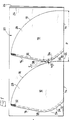
- the filter horns 10 shown in FIG. 1 are laid out flat along a generally trapezoidal contour with a bottom edge 12, two divergent rectilinear side edges 14 and 16, and an opening edge 18.
- These horns are formed in series by cutting from a strip of filter paper 20 folded along its median longitudinal axis 22 to obtain two superimposed sheets 24 and 26.
- One of the lateral edges 14 of each horn is formed by the median fold 22; cutting is carried out on the remaining part of the outline of each horn to form respectively in the two sheets 24 and 26 the two opposite walls 28 and 30 of this horn; these walls are joined to each other by an assembly edge 32 extending along the other lateral edge 16 and along the bottom edge 12; this assembly border is obtained, for example, by embossing the paper according to a usual technique.
- the bottom edge 12 has, in its region adjacent to the side edge 16, a curvilinear shape whose concavity is turned towards the opening edge 18, and which tangentially connects to the side edge 16.
- this curvilinear part 34 of the bottom edge 12 has the shape of a sector of a circle which extends from the central zone 36 of the bottom edge 12 to the point of tangency 38 with the edge 16 .
- the reference P shows the pitch between two successive horns, that is to say the length of the strip of paper 20 necessary for making each horn.
- the invention therefore allows a saving of paper which can be evaluated at a percentage equal to the d / P ratio, that is to say a few percent. This saving is by no means negligible in the case of very large series of filter cones.
Landscapes
- Engineering & Computer Science (AREA)
- Food Science & Technology (AREA)
- Apparatus For Making Beverages (AREA)
- Tea And Coffee (AREA)
- Machines For Manufacturing Corrugated Board In Mechanical Paper-Making Processes (AREA)
- Packages (AREA)
- Infusion, Injection, And Reservoir Apparatuses (AREA)
- Lubrication Details And Ventilation Of Internal Combustion Engines (AREA)
- Piezo-Electric Or Mechanical Vibrators, Or Delay Or Filter Circuits (AREA)
- Separation Using Semi-Permeable Membranes (AREA)
Description
- L'invention se rapporte aux cornets-filtres en papier, en particulier pour infusion de café, qui se présentent à plat selon un contour de forme générale trapézoïdale avec une arête de fond, deux arêtes latérales rectilignes divergentes, et un bord d'ouverture.
- Un cornet-filtre de ce genre a été décrit, par exemple, dans le brevet allemand DE 640 946, en référence aux figures 1 et 2 de ce brevet.
- Selon un procédé connu, ces cornets sont formés en série par découpage dans une bande de papier filtrant pliée selon son axe longitudinal médian pour obtenir deux feuillets superposés, l'une desdites arêtes latérales de chaque cornet étant formée par ledit pli médian, et ledit découpage étant effectué sur la partie restante du contour de chaque cornet pour former respectivement dans les deux dits feuillets les deux parois opposées du cornet, ces parois étant en outre unies l'une à l'autre par une bordure d'assemblage, obtenue par exemple par gaufrage, qui s'étend le long de l'autre arête latérale et le long de l'arête de fond de chaque cornet.
- Dans les cornets-filtres connus de ce genre l'arête de fond est rectiligne et se raccorde donc par un angle à chaque arête latérale. Dans d'autres cornets-filtres connus, l'arête de fond rectiligne se raccorde par un angle à l'arête latérale formé par ledit pli, tandis que l'arête de fond, dans sa région adjacente à l'autre arête latérale, présente une forme curviligne dont la concavité est tournée vers le bord d'ouverture, cette partie curviligne se raccordant tangentiellement à ladite autre arête latérale rectiligne.
- Les cornets-filtres ainsi formés connus présentent une arête de fond qui a la forme rectiligne surtou- te sa longueur ou au moins sur la plus grande partie de sa longueur, et qui, de ce fait, repose dans l'usage de façon régulière sur l'arête de fond rectiligne correspondante du support du filtre. Ainsi, la bordure d'assemblage du cornet-filtre s'étendant selon l'arête de fond est soumise à une pression régulièrement répartie lors de son usage.
- Lorsque les cornets-filtres sont découpés en série, l'un derrière l'autre, dans la même bande de papier selon le procédé exposé ci-dessus, la saillie formée par cet angle ou même par ladite partie curviligne à l'arrière de chaque découpe oblige à utiliser pour chaque cornet une longueur de papier relativement grande se traduisant par des déchets importants.
- L'invention a pour but de réduire, de manière non négligeable, les déchets résultant des chutes de papier après découpage.
- Un cornet-filtre selon l'invention est caractérisé en ce que ladite partie curviligne de son arête de fond présente la forme d'un secteur de cercle s'étendant depuis la zone centrale de l'arête de fond jusqu'au point de tangence avec ladite autre arête latérale rectiligne.
- Ainsi, lors de l'opération de découpage, la saillie formée à l'arrière de chaque découpage est, en quelque sorte, rognée ou amoindrie ce qui permet de réduire quelque peu le pas entre deux cornets successifs, c'est-à-dire la longueur de papier nécessaire à la confection de chacun, sans pour autant réduire pratiquement leur capacité interne, et sans nuire à leur usage facile et positionnement correct.
- Les caractéristiques et avantages de l'invention ressortiront d'ailleurs de la description qui va suivre, à titre d'exemple, en référence aux dessins annexés dans lesquels :
- la figure 1 représente une bande de papier filtrant pliée dans laquelle sont réalisés des cornets selon l'invention; la figure 2 représente, à fin d'illustration, un cornet selon l'invention tel qu'il se présenterait si, après l'opération de découpage, et avant l'opération d'assemblage par gaufrage, on déployait dans un plan le flan de papier qui le constitue.
- Les cornets-filtres 10 représentés à la figure 1 se présentent à plat selon un contour de forme générale trapézoïdale avec une arête de fond 12, deux arêtes latérales rectilignes divergentes 14 et 16, et un bord d'ouverture 18.
- Ces cornets sont formés en série par découpage dans une bande de papier filtrant 20 pliée selon son axe longitudinal médian 22 pour obtenir deux feuillets superposés 24 et 26. L'une des arêtes latérales 14 de chaque cornet est formée par le pli médian 22 ; le découpage est effectué sur la partie restante du contour de chaque cornet pour former respectivement dans les deux feuillets 24 et 26 les deux parois opposées 28 et 30 de ce cornet ; ces parois sont unies l'une à l'autre par une bordure d' assemblage 32 s'étendant le long de l'autre arête latérale 16 et le long de l'arête de fond 12 ; cette bordure d'assemblage est obtenue, par exemple, par gaufrage du papier selon une technique usuelle.
- L'arête de fond 12 présente, dans sa région adjacente à l'arête latérale 16, une forme curviligne dont la concavité est tournée vers le bord d'ouverture 18, et qui se raccorde tangentiellement à l'arête latérale 16. Selon la présente invention, cette partie curviligne 34 de l'arête de fond 12 présente la forme d'un secteur de cercle qui s'étend depuis la zone centrale 36 de l'arête de fond 12 jusqu'au point de tangence 38 avec l'arête 16.
- Comme on le voit sur la figure 1, lors de l'opération de découpage on laisse entre deux cornets successifs un espace E compatible avec une bonne découpe sans déchirure du papier. Sur cette figure, on a représenté par la référence P le pas entre deux cornets successifs, c'est-à-dire la longueur de la bande 20 de papier nécessaire à la confection de chaque cornet.
- Comme on le comprend, si l'arête de fond 12, au lieu d'être curviligne, avait été rectiligne, comme par exemple dans le brevet allemand DE 640 946, une saillie angulaire serait apparue à l'arrière de chaque découpe comme indiqué en traits interrompus par la référence 40 de la figure 1, et il aurait alors fallu augmenter le pas P d'une quantité égale à la distance axiale d entre la pointe 40 et la partie curviligne 34, étant bien entendu qu'il aurait encore fallu conserver un espace E entre la pointe 40 et le bord 18 du cornet suivant.
- L'invention permet donc une économie de papier que l'on peut évaluer à un pourcentage égal au rapport d/P, c'est-à-dire de quelques pour cent. Cette économie n'est nullement négligeable dans le cas d'une fabrication de cornets-filtres en très grande série.
Claims (1)
Priority Applications (1)
| Application Number | Priority Date | Filing Date | Title |
|---|---|---|---|
| AT83110404T ATE40516T1 (de) | 1982-10-22 | 1983-10-19 | Filtertuete, insbesondere zur kaffeezubereitung. |
Applications Claiming Priority (2)
| Application Number | Priority Date | Filing Date | Title |
|---|---|---|---|
| FR8217723 | 1982-10-22 | ||
| FR8217723A FR2534797B1 (fr) | 1982-10-22 | 1982-10-22 | Cornet-filtre, en particulier pour infusion de cafe |
Publications (4)
| Publication Number | Publication Date |
|---|---|
| EP0107174A2 EP0107174A2 (fr) | 1984-05-02 |
| EP0107174A3 EP0107174A3 (en) | 1987-02-04 |
| EP0107174B1 EP0107174B1 (fr) | 1989-02-01 |
| EP0107174B2 true EP0107174B2 (fr) | 1993-02-03 |
Family
ID=9278513
Family Applications (1)
| Application Number | Title | Priority Date | Filing Date |
|---|---|---|---|
| EP83110404A Expired - Lifetime EP0107174B2 (fr) | 1982-10-22 | 1983-10-19 | Cornet-filtre, en particulier pour infusion de café |
Country Status (6)
| Country | Link |
|---|---|
| EP (1) | EP0107174B2 (fr) |
| AT (1) | ATE40516T1 (fr) |
| DE (1) | DE3379097D1 (fr) |
| ES (1) | ES275143Y (fr) |
| FR (1) | FR2534797B1 (fr) |
| PT (1) | PT77548B (fr) |
Families Citing this family (2)
| Publication number | Priority date | Publication date | Assignee | Title |
|---|---|---|---|---|
| FI86159C (fi) * | 1990-08-29 | 1992-07-27 | Ahlstroem Consumer Prod | Foerfarande foer tillverkning av filterpaosar och filterpaose. |
| AU5158899A (en) | 1999-07-13 | 2000-11-21 | Braun Gmbh | Filter bag consisting of filter paper for producing brewed beverages such as coffee or tea, stack of filter bags of this type and method for producing filter bags of this type |
Family Cites Families (3)
| Publication number | Priority date | Publication date | Assignee | Title |
|---|---|---|---|---|
| NL45428C (fr) * | 1935-07-25 | |||
| FR1478980A (fr) * | 1966-05-06 | 1967-04-28 | Sac filtrant destiné à la préparation d'une infusion de café, et procédé de fabrication dudit sac | |
| DE2929194A1 (de) * | 1978-09-21 | 1980-04-03 | Walter Oldani | Verfahren und vorrichtung zum herstellen von filtertueten und filtertuete |
-
1982
- 1982-10-22 FR FR8217723A patent/FR2534797B1/fr not_active Expired
-
1983
- 1983-10-19 EP EP83110404A patent/EP0107174B2/fr not_active Expired - Lifetime
- 1983-10-19 AT AT83110404T patent/ATE40516T1/de not_active IP Right Cessation
- 1983-10-19 DE DE8383110404T patent/DE3379097D1/de not_active Expired
- 1983-10-21 PT PT77548A patent/PT77548B/fr not_active IP Right Cessation
- 1983-10-21 ES ES1983275143U patent/ES275143Y/es not_active Expired
Also Published As
| Publication number | Publication date |
|---|---|
| EP0107174A2 (fr) | 1984-05-02 |
| EP0107174A3 (en) | 1987-02-04 |
| ES275143Y (es) | 1985-05-01 |
| DE3379097D1 (en) | 1989-03-09 |
| PT77548B (fr) | 1986-03-12 |
| ES275143U (es) | 1984-07-01 |
| FR2534797A1 (fr) | 1984-04-27 |
| FR2534797B1 (fr) | 1987-11-20 |
| EP0107174B1 (fr) | 1989-02-01 |
| ATE40516T1 (de) | 1989-02-15 |
| PT77548A (fr) | 1983-11-01 |
Similar Documents
| Publication | Publication Date | Title |
|---|---|---|
| EP1060850B1 (fr) | Procédé de découpage/refoulage d'éléments plats adjacents et dispositif pour sa mise en oeuvre. | |
| FR2541231A1 (fr) | Montage de plans additionnels en bouts d'ailes | |
| EP0216164B1 (fr) | Procédé de fabrication en continu d'un matelas absorbant en forme de sablier pour une couche-culotte | |
| EP0107174B1 (fr) | Cornet-filtre, en particulier pour infusion de café | |
| FR2481231A1 (fr) | Emballage a poignee, en carton, carton ondule ou autre materiau en feuille, et flan et ebauche propres a la constitution d'un tel emballage | |
| EP1540229B1 (fr) | Collier de serrage | |
| EP2072408B1 (fr) | Flan prédécoupé pour la réalisation d'un élément d'emballage à fond renforcé | |
| FR2609965A1 (fr) | Emballage du genre caisse, en particulier caisse a legumes en carton, carton ondule ou autre materiau en feuille | |
| FR2532277A1 (fr) | Boite en deux parties | |
| EP0914567B1 (fr) | Disque a garnitures de friction pour embrayage mecanique | |
| FR2629151A1 (fr) | Agrafe, en particulier pour l'assemblage de baguettes de bois | |
| EP0114771A2 (fr) | Flan pour la constitution d'un emballage sur lequel doit être rapportée une poignée, et ébauche d'emballage et emballage correspondants | |
| FR2634456A1 (fr) | Emballage a poignee et flan propre a la constitution d'un tel emballage | |
| FR2585001A1 (fr) | Emballage a rabats de calage modulables en hauteur, en carton, carton ondule ou autre materiau en feuille convenablement decoupe et plie, et flan correspondant | |
| FR2641257A1 (fr) | Boite en carton ou similaire de forme polygonale presentant un rebord de butee pour le couvercle | |
| FR2537055A1 (fr) | Procede pour la realisation de filtres a cafe ou analogues | |
| EP1771341B1 (fr) | Barquette en bois deroule de forme octogonale | |
| FR2645796A1 (fr) | Organe conformateur pour la realisation d'une chemise de classement a volets articules avec au moins un rabat | |
| FR2525148A1 (fr) | Procede de decoupe de caisses en carton a base rectangulaire et caisses obtenues par ce procede | |
| FR2493271A1 (fr) | Rabat a poignee pour emballage, en carton, carton ondule ou autre materiau en feuille, flan en un tel materiau comportant un tel rabat, et emballage correspondant | |
| FR2463064A1 (fr) | Emballage parallelepipedique a poignee, notamment pour le conditionnement de couches, et flan et ebauche tubulaires correspondants | |
| EP1713650A1 (fr) | Organe de liaison en tole destine a etre soude avec un autre element et presentant une surface d'accostage; procede de fabrication, matrice d'emboutissage et vehicule correspondants | |
| FR2632273A1 (fr) | Barquette | |
| FR2688489A1 (fr) | Corps de boite parallelepipedique en carton a fond de type americain, et flan correspondant. | |
| FR2623749A1 (fr) | Chemise extensible pour l'archivage de documents et procede pour sa fabrication |
Legal Events
| Date | Code | Title | Description |
|---|---|---|---|
| PUAI | Public reference made under article 153(3) epc to a published international application that has entered the european phase |
Free format text: ORIGINAL CODE: 0009012 |
|
| AK | Designated contracting states |
Designated state(s): AT BE CH DE GB IT LI NL SE |
|
| 17P | Request for examination filed |
Effective date: 19841219 |
|
| PUAL | Search report despatched |
Free format text: ORIGINAL CODE: 0009013 |
|
| AK | Designated contracting states |
Kind code of ref document: A3 Designated state(s): AT BE CH DE GB IT LI NL SE |
|
| RAP1 | Party data changed (applicant data changed or rights of an application transferred) |
Owner name: MOULINEX |
|
| 17Q | First examination report despatched |
Effective date: 19880712 |
|
| GRAA | (expected) grant |
Free format text: ORIGINAL CODE: 0009210 |
|
| AK | Designated contracting states |
Kind code of ref document: B1 Designated state(s): AT BE CH DE GB IT LI NL SE |
|
| REF | Corresponds to: |
Ref document number: 40516 Country of ref document: AT Date of ref document: 19890215 Kind code of ref document: T |
|
| GBT | Gb: translation of ep patent filed (gb section 77(6)(a)/1977) | ||
| REF | Corresponds to: |
Ref document number: 3379097 Country of ref document: DE Date of ref document: 19890309 |
|
| ITF | It: translation for a ep patent filed | ||
| PLBI | Opposition filed |
Free format text: ORIGINAL CODE: 0009260 |
|
| 26 | Opposition filed |
Opponent name: MELITTA-WERKE BENTZ & SOHN Effective date: 19891102 |
|
| NLR1 | Nl: opposition has been filed with the epo |
Opponent name: MELITTA-WERKE BENTZ & SOHN |
|
| ITTA | It: last paid annual fee | ||
| PUAH | Patent maintained in amended form |
Free format text: ORIGINAL CODE: 0009272 |
|
| STAA | Information on the status of an ep patent application or granted ep patent |
Free format text: STATUS: PATENT MAINTAINED AS AMENDED |
|
| 27A | Patent maintained in amended form |
Effective date: 19930203 |
|
| AK | Designated contracting states |
Kind code of ref document: B2 Designated state(s): AT BE CH DE GB IT LI NL SE |
|
| REG | Reference to a national code |
Ref country code: CH Ref legal event code: AEN |
|
| NLR2 | Nl: decision of opposition | ||
| NLR3 | Nl: receipt of modified translations in the netherlands language after an opposition procedure | ||
| ITF | It: translation for a ep patent filed | ||
| GBTA | Gb: translation of amended ep patent filed (gb section 77(6)(b)/1977) |
Effective date: 19930331 |
|
| PGFP | Annual fee paid to national office [announced via postgrant information from national office to epo] |
Ref country code: AT Payment date: 19941014 Year of fee payment: 12 |
|
| EAL | Se: european patent in force in sweden |
Ref document number: 83110404.7 |
|
| PG25 | Lapsed in a contracting state [announced via postgrant information from national office to epo] |
Ref country code: AT Effective date: 19951019 |
|
| PGFP | Annual fee paid to national office [announced via postgrant information from national office to epo] |
Ref country code: SE Payment date: 19971016 Year of fee payment: 15 |
|
| PGFP | Annual fee paid to national office [announced via postgrant information from national office to epo] |
Ref country code: CH Payment date: 19971104 Year of fee payment: 15 |
|
| PGFP | Annual fee paid to national office [announced via postgrant information from national office to epo] |
Ref country code: GB Payment date: 19981009 Year of fee payment: 16 |
|
| PG25 | Lapsed in a contracting state [announced via postgrant information from national office to epo] |
Ref country code: SE Free format text: LAPSE BECAUSE OF NON-PAYMENT OF DUE FEES Effective date: 19981020 |
|
| PG25 | Lapsed in a contracting state [announced via postgrant information from national office to epo] |
Ref country code: LI Free format text: LAPSE BECAUSE OF NON-PAYMENT OF DUE FEES Effective date: 19981031 Ref country code: CH Free format text: LAPSE BECAUSE OF NON-PAYMENT OF DUE FEES Effective date: 19981031 |
|
| REG | Reference to a national code |
Ref country code: CH Ref legal event code: PL |
|
| EUG | Se: european patent has lapsed |
Ref document number: 83110404.7 |
|
| PG25 | Lapsed in a contracting state [announced via postgrant information from national office to epo] |
Ref country code: GB Free format text: LAPSE BECAUSE OF NON-PAYMENT OF DUE FEES Effective date: 19991019 |
|
| PGFP | Annual fee paid to national office [announced via postgrant information from national office to epo] |
Ref country code: DE Payment date: 19991022 Year of fee payment: 17 |
|
| GBPC | Gb: european patent ceased through non-payment of renewal fee |
Effective date: 19991019 |
|
| PGFP | Annual fee paid to national office [announced via postgrant information from national office to epo] |
Ref country code: NL Payment date: 20001031 Year of fee payment: 18 |
|
| PG25 | Lapsed in a contracting state [announced via postgrant information from national office to epo] |
Ref country code: DE Free format text: LAPSE BECAUSE OF NON-PAYMENT OF DUE FEES Effective date: 20010703 |
|
| PGFP | Annual fee paid to national office [announced via postgrant information from national office to epo] |
Ref country code: BE Payment date: 20011214 Year of fee payment: 19 |
|
| PG25 | Lapsed in a contracting state [announced via postgrant information from national office to epo] |
Ref country code: NL Free format text: LAPSE BECAUSE OF NON-PAYMENT OF DUE FEES Effective date: 20020501 |
|
| NLV4 | Nl: lapsed or anulled due to non-payment of the annual fee |
Effective date: 20020501 |
|
| PG25 | Lapsed in a contracting state [announced via postgrant information from national office to epo] |
Ref country code: BE Free format text: LAPSE BECAUSE OF NON-PAYMENT OF DUE FEES Effective date: 20021031 |
|
| BERE | Be: lapsed |
Owner name: *MOULINEX Effective date: 20021031 |