EP0107328A2 - Débitmètre à orifice avec dispositif de sécurité pour diminuer et égaliser la pression - Google Patents
Débitmètre à orifice avec dispositif de sécurité pour diminuer et égaliser la pression Download PDFInfo
- Publication number
- EP0107328A2 EP0107328A2 EP83305458A EP83305458A EP0107328A2 EP 0107328 A2 EP0107328 A2 EP 0107328A2 EP 83305458 A EP83305458 A EP 83305458A EP 83305458 A EP83305458 A EP 83305458A EP 0107328 A2 EP0107328 A2 EP 0107328A2
- Authority
- EP
- European Patent Office
- Prior art keywords
- valve
- seal
- sleeve
- ring
- plug
- Prior art date
- Legal status (The legal status is an assumption and is not a legal conclusion. Google has not performed a legal analysis and makes no representation as to the accuracy of the status listed.)
- Ceased
Links
Images

Classifications
-
- G—PHYSICS
- G01—MEASURING; TESTING
- G01F—MEASURING VOLUME, VOLUME FLOW, MASS FLOW OR LIQUID LEVEL; METERING BY VOLUME
- G01F1/00—Measuring the volume flow or mass flow of fluid or fluent solid material wherein the fluid passes through a meter in a continuous flow
- G01F1/05—Measuring the volume flow or mass flow of fluid or fluent solid material wherein the fluid passes through a meter in a continuous flow by using mechanical effects
- G01F1/34—Measuring the volume flow or mass flow of fluid or fluent solid material wherein the fluid passes through a meter in a continuous flow by using mechanical effects by measuring pressure or differential pressure
- G01F1/36—Measuring the volume flow or mass flow of fluid or fluent solid material wherein the fluid passes through a meter in a continuous flow by using mechanical effects by measuring pressure or differential pressure the pressure or differential pressure being created by the use of flow constriction
- G01F1/40—Details of construction of the flow constriction devices
- G01F1/42—Orifices or nozzles
Definitions
- Natural gas is generally sold by volumetric measurement, and one way to measure the volume of a flowing gas is to pass it through an orifice of a known size and measure the pressure drop across it.
- An orifice meter comprises a housing within which a disc with an orifice is supported in a gas pipeline, the housing being fitted with pressure taps for measuring pressure immediately upstream and downstream of the orifice. Because the orifice is subject to wear by impacting of sand, lime scale and other foreign particles in the flowing stream, it must be replaced at frequent intervals to ensure accuracy in measurement.
- the orifice disc carrier is moved to a location in the housing which may be sealed off from the flow passage so that flow can continue while the orifice disc is being replaced.
- a closure covering an access opening in a wall of the meter housing is removed so to enable service or replacement of the orifice disc.
- the closure is removed or loosened while the body compartment is still under pressure, serious or even catastrophic consequences may ensue.
- the orifice meter housing of this invention has a pair of parallel plates with a gate-like orifice disc carrier slidable between them. In one position, resilient seal rings on opposite sides of the carrier seal around the flow passages, and in a second position, the seal ring on one side seals around an access opening while the other seal ring seals against the opposite wall so that, together they form an isolated chamber exposed to the access opening.
- the isolated chamber is connected by a transfer duct to an adjacent flow passageway through one of the parallel plates.
- An axially movable valve plug is normally in an axially retracted position wherein an equalizing port is uncovered so that pressures in the isolation chamber and the remainder of the body chamber are equalized through the transfer duct.
- the valve plug is moved inward to close the equalizing port and open a venting port, so that the isolation chamber is vented through the transfer duct to the atmosphere.
- the closure for the access opening must be turned at least partially to open, as by threading it into the body plate, and an arm on the closure engages the axially movable valve plug only when it is in its normal, retracted pressure-balancing position. Hence, the closure cannot be unscrewed and opened unless and until the axially movable valve is moved inward to its pressure venting position.
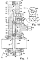
- the orifice meter 10 of this invention comprises a pair of parallel steel body plates 12 and 14, which are secured together by a plurality of bolts 16, with nuts 17 clamping the plates 12 and 14 against the edges of an oval body band 18.
- Resilient seal rings 20, which are carried by the body band 18 form a sealed body space enclosure 21 between the body plates 12 and 14.
- a gate-like carrier 22 which is of annular configuration with an opening 24 therethrough, counterbored at 26 to form an internal shoulder 28, against which is supported the orifice disc 30 having an orifice 32 therethrough of a predetermined size.
- An annular axial flange 34 on the orifice disc 30 carries a seal ring 36 to prevent the occurrence of a leak path around the orifice disc 30.
- the internal diameter of the axial flange 34, as well as the internal diameter of the opening 24 is substantially equal to the internal diameters of the flow tubes 38, so that when in active position shown in phantom aligned with the flow tubes 38, they form a continuation thereof.
- the flow tubes 38 may each comprise a section of a pipe of predetermined diameter, which is dictated by the various factors governing flow measurement.
- the flow tubes 38 are welded at 40 into a mounting ring 41.
- the mounting ring 41 and flow tube 38 are sealed at 42 and secured to the valve plates 12 and 14, as by means of cap screws 43.
- Pressure taps 44 and 45 are drilled at fixed distances upstream and downstream of the orifice disc 30 so that, when the carrier 22 is in its active position shown in phantom, the pressure drop across the orifice 32 can be determined.
- a seat ring 46 Carried on each side of the annular orifice disc carrier 22 is a seat ring 46 carrying a resilient outer seal 48 and a resilient main seal 50.
- the main seals 50 on opposite sides of the carrier 22 maintain constant sealing engagement with the valve plates 12 and 14 so that, in any position thereof, away from the flow tubes 38, the portion of the orifice carrier radially inside the main seal rings 50 constitutes an isolation chamber 51, which is sealed off from the remainder of the valve body space 21.
- the orifice carrier 22 has an integral, panhandle stem 52 which is pivoted at 54 on a crank arm 56, carried on a sealed, rotatable shaft 58 with a squared end 60 for partial rotation, as by means of a suitable wrench (not shown).
- a service access opening 62 Displaced from the flow passageways 38 is a service access opening 62, through which the orifice disc 30 may be serviced or replaced, when the carrier is moved into position in alignment with the opening 62, as shown in solid lines in FIG. 1.
- the access opening 62 is normally closed by a closure member 64, as by providing complementary, engagable Acme threads 66 on the opening 62 and closure 64.
- Suitable seal means such as an O-ring 68 may be provided to prevent leakage past the threads 66.
- the closure 64 may be unthreaded from the opening 62, by applying a wrench to the squared end 70 of a stem 72, which is secured to, or formed integral with, the closure 64.
- a venting and equalizing valve assembly 74 Closely spaced from the access opening 62,and connected to it by a transfer duct 73, is a venting and equalizing valve assembly 74, including an axially movable valve plug 76, the operation of which will be described hereinafter.
- a lock arm 78 Secured to the access opening closure 64 by any suitable means 77 is a lock arm 78 with a recess or yoke 80 (FIG. 1A) overlying the end of the axially movable valve plug 76.
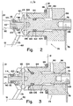
- the pressure venting-equalizing valve 74 is shown in its normal position, as occurs while the valve carrier 22 is in alignment with the flow tubes 38, as shown in phantom in FIG. 1.
- the pressure venting-equalizing valve 74 includes a bore 80 opening from the inside of wall plate 12 from the body space 21, and a coaxial counterbore 82 opening from the outer wall of the plate 12.
- the counterbore 82 is tapped at 84 to threadedly receive a sleeve 86, with a seal, such as an O-ring 88 preventing leakage around the sleeve 86.
- a generally radial venting passage 90 is provided from the inside of the sleeve 86 to the atmosphere.
- valve body plug 76 Formed around the axially movable valve body plug 76 is an annular groove or recess 100 in which is carried a vent seal O-ring 102.
- the O-ring 102 engages the inner surface 104 of the sleeve 86, so that, as long as the O-ring 102 is engaged in the sleeve 86, there can be no venting through the passageways 90 from either the body space 21 or the confined space 51.
- Complementary threads 106 on the valve plug 76 and the sleeve 86 cause the valve plug 76 to be moved axially upon rotation thereof, as a means of a suitable wrench in the end socket 108.
- valve plug 76 In the normal position shown in FIG. 2, the valve plug 76 is fully retracted with an extension 110 thereon partially withdrawn from the bore 80 wherein an equalizing O-ring 112 carried in a groove 114 is out of sealing engagement with the bore 80. In this position, which is defined by engagement of a collar with the end of the sleeve 86, there is pressure equalizing communication between the body space 21 and the isolation space 51.
- the recess 114 is formed by the extension 110 which is pinned at 116 to the plug to extend therefrom and the annular end 118 of the plug itself.
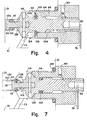
- the pressure venting-equalizing valve plug 76 is in its intermediate position with the forward extension 110 and leading O-ring seal 112 entered into the bore 80 to seal off communication from the body interior 21. It is significant to note that the sealing of the bore 80 by the O-ring 112 is established before the venting O-ring 102 emerges from the inner surface 104 of the sleeve 86. Hence, the bore 80 and body space 21 are sealed off, before there can be any venting to the atmosphere through the radial passages 90 of the sleeve 86.
- the axially movable plug 76 has moved to a position wherein the venting O-ring 102 has fully emerged from the inner surface 104 of the sleeve 86, with the collar 115 engaging the bottom of the counterbore 82.
- the isolated space 51 is open to atmosphere through venting ducts 73 and 90.
- the O-ring 102 just emerges from the sleeve 86, it tends to cling to the sleeve inner surface 104 and at the same time, there is a rush of pressure toward the venting duct 80, which tends to blow the O-ring 102 out of its recess 100.
- the end of the sleeve 86 is chamfered at 124 so that there is an internal conical surface that restricts outer radial expansion of the O-ring 102.
- there are Vee grooves 126 which provide a bypass for initial flow of the venting fluid toward the outer duct 90 to equalize pressures, allowing the O-ring 102 to reach a position of stability, as shown in FIG. 5, wherein venting continues to the atmosphere through the radial passages 90.
- the axially movable plug 76 is free of the arm 78, enabling rotation of the threaded access opening closure 64 for service of the orifice disc 30.
- valve 76 is shown being retracted, with the forward O-ring 112 just emerging from the bore 80. Again, there is a tendency for the O-ring both to cling to the surface 80 and to be blown from the O-ring recess 114 by the sudden rush of pressure from the body space 21 to equalize with the isolated space 51 through the passage 73.
- a restricting chamf er 128 is provided at the inner end of the bore 80 and the vent passages 122 enable the fluid to bypass the O-ring 112 until it stablizes to the position shown in FIG. 1.
- the lips 120 around the recess 114 provide mechanical restraining means for retention of the O-ring 112.
- the vent passages 122 have a total area several times greater than the clearance gap 110a around the extension 110. This greatly reduces differential pressure across the O-ring enabling it to snap back into its groove 114 under its own tension.
Landscapes
- Physics & Mathematics (AREA)
- Fluid Mechanics (AREA)
- General Physics & Mathematics (AREA)
- Self-Closing Valves And Venting Or Aerating Valves (AREA)
- Measuring Volume Flow (AREA)
- Safety Valves (AREA)
Applications Claiming Priority (2)
| Application Number | Priority Date | Filing Date | Title |
|---|---|---|---|
| US06/429,621 US4476730A (en) | 1982-09-30 | 1982-09-30 | Orifice meter with pressure venting and equalizing safety device |
| US429621 | 1982-09-30 |
Publications (2)
| Publication Number | Publication Date |
|---|---|
| EP0107328A2 true EP0107328A2 (fr) | 1984-05-02 |
| EP0107328A3 EP0107328A3 (fr) | 1984-07-11 |
Family
ID=23704031
Family Applications (1)
| Application Number | Title | Priority Date | Filing Date |
|---|---|---|---|
| EP83305458A Ceased EP0107328A3 (fr) | 1982-09-30 | 1983-09-16 | Débitmètre à orifice avec dispositif de sécurité pour diminuer et égaliser la pression |
Country Status (4)
| Country | Link |
|---|---|
| US (1) | US4476730A (fr) |
| EP (1) | EP0107328A3 (fr) |
| JP (1) | JPS59131117A (fr) |
| CA (1) | CA1190415A (fr) |
Cited By (1)
| Publication number | Priority date | Publication date | Assignee | Title |
|---|---|---|---|---|
| EP0242825A3 (en) * | 1986-04-18 | 1989-10-11 | Fujikin International, Inc. | Apparatus for interchanging orifice plates for orifice flowmeter |
Families Citing this family (12)
| Publication number | Priority date | Publication date | Assignee | Title |
|---|---|---|---|---|
| JP2557330Y2 (ja) * | 1991-12-09 | 1997-12-10 | 住友建機株式会社 | クレ−ンにおけるドラムブレ−キ調整機構 |
| US5464036A (en) * | 1994-02-09 | 1995-11-07 | Valgro, Ltd. | Orifice fitting with venting passage and injection seal |
| US5464035A (en) * | 1994-06-21 | 1995-11-07 | Itt Corporation | Gate-type, side-ported, line blind valve |
| US5758692A (en) * | 1995-03-15 | 1998-06-02 | Crane Manufacturing, Inc. | Orifice fitting |
| US5778933A (en) * | 1995-03-15 | 1998-07-14 | Crane Manufacturing, Inc. | Orifice fitting |
| US9062994B2 (en) * | 2007-06-15 | 2015-06-23 | Dieterich Standard, Inc. | Locating of pressure taps on face of orifice plate device |
| MY183270A (en) | 2013-02-15 | 2021-02-18 | Derold Clark | Method and apparatus for installing and removing a flow restrictor from a differential pressure measurement device |
| CA2853935C (fr) | 2014-06-09 | 2019-09-24 | Derold Gary Clark | Dispositif de retenue d'une bande de valve |
| MX389682B (es) * | 2014-12-12 | 2025-03-20 | Daniel Opco Llc | Sistema de multi-doble bloqueo y purgado para un orificio conector |
| US9651410B2 (en) | 2015-03-31 | 2017-05-16 | Dieterich Standard, Inc. | Paddle style orifice plate with integral pressure ports |
| DE102017114977B4 (de) * | 2017-07-05 | 2022-04-28 | Postberg + Co. GmbH | Wechselarmatur |
| CN117053881B (zh) * | 2023-08-30 | 2025-11-18 | 北京博思达新世纪测控技术有限公司 | 一种宽量程的差压强式流量计及其差压强流量测定方法 |
Family Cites Families (6)
| Publication number | Priority date | Publication date | Assignee | Title |
|---|---|---|---|---|
| DE1935899C3 (de) * | 1969-07-15 | 1980-01-10 | Baezold, Karl, 6000 Frankfurt | Selbsttätiges Entlüftungsventil |
| CH631531A5 (en) * | 1978-02-01 | 1982-08-13 | Rolf Keller | Valve for bleeding radiators |
| US4191216A (en) * | 1978-07-10 | 1980-03-04 | Daniel Industries, Inc. | Fabricated orifice fitting mechanism for pipelines |
| GB2049953B (en) * | 1979-02-17 | 1983-05-25 | Dawson R W | Fluid low measuring apparatus |
| FR2470326B1 (fr) * | 1979-11-19 | 1986-05-23 | Reglerbau Mannemann Gmbh Co Kg | Dispositif porte-orifice pour mesure de debit dans les canalisations sous pression |
| US4370893A (en) * | 1981-06-08 | 1983-02-01 | Grove Valve And Regulator Company | Orifice meter with replacable orifice disc |
-
1982
- 1982-09-30 US US06/429,621 patent/US4476730A/en not_active Expired - Fee Related
-
1983
- 1983-09-16 EP EP83305458A patent/EP0107328A3/fr not_active Ceased
- 1983-09-22 CA CA000437302A patent/CA1190415A/fr not_active Expired
- 1983-09-29 JP JP58179458A patent/JPS59131117A/ja active Pending
Cited By (1)
| Publication number | Priority date | Publication date | Assignee | Title |
|---|---|---|---|---|
| EP0242825A3 (en) * | 1986-04-18 | 1989-10-11 | Fujikin International, Inc. | Apparatus for interchanging orifice plates for orifice flowmeter |
Also Published As
| Publication number | Publication date |
|---|---|
| EP0107328A3 (fr) | 1984-07-11 |
| JPS59131117A (ja) | 1984-07-27 |
| US4476730A (en) | 1984-10-16 |
| CA1190415A (fr) | 1985-07-16 |
Similar Documents
| Publication | Publication Date | Title |
|---|---|---|
| US4370893A (en) | Orifice meter with replacable orifice disc | |
| US4476730A (en) | Orifice meter with pressure venting and equalizing safety device | |
| US4593915A (en) | Orifice plate seal ring | |
| US4972867A (en) | Valve stem seal leak protection and detection apparatus | |
| US3591131A (en) | Railroad tank car ball valve | |
| US4478251A (en) | Orifice fitting seal assembly | |
| US3955591A (en) | Insert type sliding gate valve | |
| US5186199A (en) | Conduit stopper | |
| CA1175318A (fr) | Soupape annulaire coulissante | |
| US4393722A (en) | Flow measuring device | |
| US8167268B2 (en) | Dual chamber orifice fitting plate support | |
| US3765448A (en) | Flow control valve | |
| US2872939A (en) | Flow control valve | |
| US4313462A (en) | Sequentially operated valve structure | |
| US6062540A (en) | Double seal drain cock | |
| US2931380A (en) | Lubricated rotary plug valve | |
| EP0070094B1 (fr) | Montage de tuyaux pour débitmètres porte-orifice | |
| US4529167A (en) | Valve apparatus | |
| US4256137A (en) | Check valve | |
| US3097660A (en) | Check valve with removable filter | |
| EP0522708A2 (fr) | Débitmètre | |
| US4413532A (en) | Orifice meter with isolation valve on the carrier | |
| US5201344A (en) | Emissions eliminator blind | |
| US4864871A (en) | Transducer for fluid flow | |
| WO1989011611A1 (fr) | Clapet antirefouleur |
Legal Events
| Date | Code | Title | Description |
|---|---|---|---|
| PUAI | Public reference made under article 153(3) epc to a published international application that has entered the european phase |
Free format text: ORIGINAL CODE: 0009012 |
|
| AK | Designated contracting states |
Designated state(s): DE FR GB IT NL |
|
| PUAL | Search report despatched |
Free format text: ORIGINAL CODE: 0009013 |
|
| AK | Designated contracting states |
Designated state(s): DE FR GB IT NL |
|
| 17P | Request for examination filed |
Effective date: 19840810 |
|
| STAA | Information on the status of an ep patent application or granted ep patent |
Free format text: STATUS: THE APPLICATION HAS BEEN REFUSED |
|
| 18R | Application refused |
Effective date: 19861230 |
|
| RIN1 | Information on inventor provided before grant (corrected) |
Inventor name: BRUMM, RICHARD S. |