EP0107519B1 - Aktendeckel mit verstärkten Rändern und Verfahren zu dessen Herstellung - Google Patents
Aktendeckel mit verstärkten Rändern und Verfahren zu dessen Herstellung Download PDFInfo
- Publication number
- EP0107519B1 EP0107519B1 EP83306584A EP83306584A EP0107519B1 EP 0107519 B1 EP0107519 B1 EP 0107519B1 EP 83306584 A EP83306584 A EP 83306584A EP 83306584 A EP83306584 A EP 83306584A EP 0107519 B1 EP0107519 B1 EP 0107519B1
- Authority
- EP
- European Patent Office
- Prior art keywords
- edge
- film
- folder
- paper stock
- extension
- Prior art date
- Legal status (The legal status is an assumption and is not a legal conclusion. Google has not performed a legal analysis and makes no representation as to the accuracy of the status listed.)
- Expired - Lifetime
Links
Images



Classifications
-
- B—PERFORMING OPERATIONS; TRANSPORTING
- B42—BOOKBINDING; ALBUMS; FILES; SPECIAL PRINTED MATTER
- B42F—SHEETS TEMPORARILY ATTACHED TOGETHER; FILING APPLIANCES; FILE CARDS; INDEXING
- B42F17/00—Card-filing arrangements, e.g. card indexes or catalogues or filing cabinets
-
- B—PERFORMING OPERATIONS; TRANSPORTING
- B42—BOOKBINDING; ALBUMS; FILES; SPECIAL PRINTED MATTER
- B42C—BOOKBINDING
- B42C7/00—Manufacturing bookbinding cases or covers of books or loose-leaf binders
-
- B—PERFORMING OPERATIONS; TRANSPORTING
- B42—BOOKBINDING; ALBUMS; FILES; SPECIAL PRINTED MATTER
- B42F—SHEETS TEMPORARILY ATTACHED TOGETHER; FILING APPLIANCES; FILE CARDS; INDEXING
- B42F21/00—Indexing means; Indexing tabs or protectors therefor
- B42F21/04—Tabs permanently fastened to sheets, papers, cards, or suspension files
Definitions
- This invention relates to file folders and more particularly to such folders having at least one reinforced edge for use in such systems and to a method of manufacture thereof.
- Side tab folders should be distinguished from top tab folders.
- Top tab folders are indexed on the upper edge parallel to the spine or fold between the front and back surfaces of the folder.
- Side tab folders are indexed on the side at right angles to the spine or fold.
- the file folders are placed upright on shelves with their side edges projecting outwardly from the shelf.
- Side tab filing systems have become most advantageous, especially in larger filing systems, because the filing and finding of folders is faster and easier. Also, side tab filing systems save floor space as compared with drawer filing.
- the colour coding of the files is not a necessity but can usually be an enhancement.
- the reinforced edge can advantageously be used in either top or lateral systems.
- the folder stock commonly used for file folders is a folder stock approximately .011 inches or .014 inches (0.28 mm or 0.36 mm) thick.
- the folders are manufactured from web stock on high speed automatic folder machines.
- this type of high tensile strength film may be bonded to the edge of a file folder to unexpectedly greatly increase the strength of the folder and its resistance to tear. Because of the thinness of the film, little bulk is added to the folder thickness and the film may be conveniently applied during the manufacture of the file folder.
- coloured adhesives which may be applied to a clear film just prior to bonding the film to the folder edge, the edge of the folder front and back panels may be provided with a distinct colour to which colour coded labels may be subsequently applied.
- An alternative to a coloured adhesive is to use a coloured paper on the folder edge which is covered by a clear film.
- Another alternative is to use coloured film which is secured to the folder edge to provide the desired colour band.
- the folders can be manufactured from web stock on high speed automatic folder machines where the high tensile strength film when bonded to the edge of a file folder unexpectedly greatly increases the strength of the folder and its resistance to tear.
- This advantage can be accomplished during the folder manufacturing process in a way that only marginally increases the manufacturing cost.
- This marginal cost factor in relation to a much superior file folder is a worthwhile and important advantage.
- Such high tensile strength film complements and increases additionally the strength of a folder edge which consists of ploughed over web stock to provide a double thickness of paper stock at the edge.
- the high tensile strength film provides a superior bonding surface for the attachment of the self adhesive indexing and colour coded labels used to identify the folders.
- a file folder of paper stock having generally rectangular front and back panels separated by a fold which extends to an edge of the folder which is formed with an integral identification extension, in which the said edge of the folder and the extension are reinforced by an adhesively secured film of plastics material which extends about the outer edge of the extension and covers both faces thereof and which is adhesively secured to the front and back panels on either side thereof along the length of the edge to reinforce the extension, the outer edge of the extension, the said edge of the folder and the intersecting fold.
- the invention extends to a method for producing a file folder of paper stock having generally rectangular front and back panels separated by a fold which extends to an edge of the folder which is formed with an integral identification extension which comprises the steps of advancing a web of paper stock from a supply roll, the web having parallel side edges and upper and lower surfaces when advanced horizontally, applying to the web stock adjacent one side edge thereof a width of a film of plastics material, wrapping the film about the one side edge and adhering it to upper and lower surface portions along said one side edge while said paper stock is moving, cutting the paper stock within the width of the adhered film along the one side edge to leave the extension and define the remaining portion of said edge of the folder, cutting the paper stock to a predetermined length to provide the front and back panels and folding the cut paper stock along a fold separating the front and back panels and extending to said folder edge.
- a method for producing a file folder of paper stock having generally rectangular front and back panels separated by a fold which extends to and is at right angles to an edge of the folder which is formed with an integral identification extension which comprises the steps of withdrawing the paper stock from a supply roll and advancing the paper stock, applying and adhering a width of reinforcing film of plastics material, drawn from a roll of such material, to one surface of the advancing paper stock adjacent one side edge thereof, folding the paper stock and the adhered film in the length of the film to produce two opposed paper stock portions with the film adhered to the exterior thereof, adhesively uniting the opposed paper stock portions and cutting the opposed paper stock portions within the width of the film to leave the extension and form the remaining portion of said edge of the folder, cutting the paper stock from the supply to provide said front and back panels and folding the cut paper stock to produce the fold separating the front and back panels and extending to said edge of the folder.
- the edge of the folder can then be die cut to provide the desired shape for the side of the folder and at the same time or at another station the web stock is die cut to produce a folder blank which is then folded about its mid-section to provide a file folder.
- the method for reinforcing side edge portions of the front and back panels of the folder comprises securing a width of reinforcing tear resistant plastic film along an edge of the paper stock for the folder.
- the film is secured to the paper stock by an adhesive with the film wrapped about the edge and along portions of both surfaces of the material adjacent the edge.
- the paper material can be cut along the edge within the width of the film to provide the desired shape for the folder edge with a tab projecting from the side edge of the back panel.
- the film as it extends along both edge surface portions of the front and back panels reinforces the projecting tab and a portion of the panels adjacent the tab. This serves to reinforce both the tab and the junction of the tab and the panel.
- Various coloured adhesives may be used with clear film, or a coloured film may be used to provide desired colour bands along the folder side to designate groups in a file system.
- the band width colour on the exterior of the front folder flap may be wider than on the exterior of the folder so that the colour designation is more noticeable when the folder lies upright on a desk.
- File folders according to this invention optionally having colour banding applied thereto are particularly useful in lateral filing systems.
- Such filing systems differ from the standard drawer type in that the file folders are placed on shelves and stand upright as they rest on the spine portion of each file. Only the side edges of the file folder project from the shelf where each folder side edge carries labels or a label defining the code for the file. It is possible to use colour coded labels with this system to provide an orderly colour array in which misfiles are easily spotted. Details of this system are discussed in previously mentioned United States Patent 4,204,639.
- File folder 10 for use in a lateral file system is shown.
- File folder 10 comprises a back panel 12 and a front panel 14.
- the back panel 12 has a top edge 16 and side edges 18 and 20.
- the front panel has top edge 22 and side edges 24 and 26.
- the bottom edges of front and back panels are interconnected at the fold or spine portion 28.
- a reinforcing film 30 is applied to both the top and bottom surfaces of panel edges 20 and 26 in the manner shown, to reinforce the folder edge generally designated 32 along the length of edges 20 and 26.
- Reinforcement of edge 32 includes reinforcing the projecting tab 32a to decrease damage by creasing or folding causing weakening and separation of the layers making up the web stock as well as reinforcing of the area securing the tab to the panel.
- This second type of reinforcing is accomplished by having a portion of the film overlie the paper web panels to distribute the local forces exerted on the tab to. a larger area of the file folder.
- labels 34 are applied over the film 30 to designate at least in part a code for the file folder. In accordance with the aforementioned United States Patent 4,204,639, these labels may be colour coded.
- the file folder 10 is formed from a file folder blank which in turn is cut from a web of file folder paper stock. As shown in Figure 2, the file folder stock is a web having side edges 38 and 40.
- the paper stock 36 has a reinforcing film 30 applied along edge 40. The film 30 is wrapped around edge 40 and secured to adjacent top and bottom surfaces, of the paper stock.
- folder edge 32 is formed by cutting web edge 40 within the width of film 30 along edge 26 to provide a cut-out portion 42.
- the folder blank is cut from the web along lines 44 and 46 either simultaneously with cutting the edge 40 or cut subsequently at another station.
- Such cut-out blank is subsequently folded along line 28 to form the folder of Figure 1.
- portion 42 cut from the web of paper stock to define the side tab 32a of the folder an undercut portion 48 is provided at the fold line 28. It is this edge portion of the folder side carrying the tab 32a and where the fold line meets the side edge which is most susceptible to wear and tear and can be ripped as the folder is used in lateral file systems, carrying baskets, carts and the like.
- the undercut portion 48 is curved at 50 to reduce sharp edges which are more likely to tear. That in conjunction with the reinforcing film 30 considerably strengthens the folder in the area of the undercut portion 48 to minimize tearing of the folder in this area.
- the corner edge of the tab 32a adjacent to the undercut area is cut at an angle as at 49 to avoid fraying and splitting of this portion of the side tab. From the standpoint of cutting the outer edge, the angled portion 49 is more accurately cut than a radius because the die cutting edge may extend well beyond the folder edge. This ensures a clean cut to the outer edge of the folder side even if the web should shift slightly laterally before being cut.
- the web of paper stock material may have a side edge folded over to provide double thickness of material along the edge.
- the edge of the web of paper stock material therefore has an underlying layer 52 which has adhesively secured thereto a folded over upper layer 54 which has an inner edge 56.
- the reinforcing film 30 is secured to the surfaces along the edge 40 of the web.
- the reinforcing film 30 is wrapped around the edge where the film is of a sufficient width to extend beyond the inner edge 56 of the folded over web stock material.
- the side tab portion 32a of the folder to be made has the reinforcing web wrapped therearound.
- the film has been cut so as to be flush with corresponding cut edges of the layers 52 and 54.
- the folder 58 comprises back panel 60 and front panel 62. Projecting outwardly from rear panel 60 is side tab 64. A reinforcing film 66 is applied to both surfaces of the side tab 64 and also along both surfaces of the edge 68 of the front panel 62. The reinforcing film 66 reinforces this entire side of the folder 58, particularly the neighbourhood of undercut at 70 where the shorter front panel 62 intersects the longer rear panel 60. As shown in Figure 6, file folder 72 has corresponding back panel 74 and front panel 76 with side tab 78. Film 80 is secured to both surfaces of the front and back panels to reinforce the panel edges and particularly the undercut portion 80a. In the embodiment of Figure 6 the undercut portion 80a is located upwardly from the fold line or spine 82 of the folder.
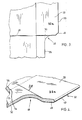
- FIG. 7 an enlarged portion of area adjacent the undercut 70 of the folder 58 of Figure 5 is shown where the film 66 is secured by an appropriate adhesive to both surfaces of the front and back panels 60 and 62.
- the notch 84 is protected by the film 66 secured to both surfaces surrounding the notch 84 to prevent or minimize tearing of the material of the folder in this area.
- the film itself may be provided in the form of a roll already having an adhesive on one face thereof, or the film may have applied thereto the adhesive with the film subsequently directly applied to folder web stock material.
- the desirable forms of adhesives are the pressure sensitive type where, if the adhesive is applied to the film and re-rolled the adhesive has less affinity for the film to which it is applied than for the paper stock material to which it is subsequently applied.
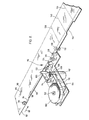
- a machine is shown which withdraws film having alreaedy applied thereto a pressure sensitive adhesive for securing the reinforcing film to the paper stock material.
- the film is of a high tensile strength tear resistant type.
- An example of such film is polyethylene terephthalate which is sold by Dupont under the Registered Trade Mark "Mylar".
- the web of paper stock 86 is withdrawn from a supply roll, (not shown), and fed in the direction of arrow 88.
- the web stock has edge portions 90 and 92. Adjacent edge portion 92, an adhesive 94 is applied by adhesive application wheel 96.
- the edge 92 is folded over in the direction of arrow 98 and adhered to the adjacent marginal edge of the paper stock by a device (not shown) to provide a double edged portion along the stock 86. This will in turn form the side edge of a folder of the type shown in the enlarged view of Figure 4.
- a supply roll 100 of reinforcing tear resistant plastic film having a pressure sensitive adhesive already thereon is mounted on a spindle 102 of the film application apparatus 104.
- Nip rollers 106 and 108 withdraw the film 110 from the supply roll 100.
- the rollers 106 and 108 are driven by a motor 112 the speed of which is coordinated with the rate of feed of the web stock 86 in the direction of arrow 88 to withdraw and feed the film 110 at a linear speed equal to the speed at which the web stock 86 is travelling in the direction of arrow 88.
- the film 110 is passed over a spring loaded arm having a roller 114 to compensate for slack in the film due to variations in the speed of the web stock 86 should the motor 112 not be capable of quickly compensating for variations in speed of the web stock 86.
- the film is then passed over a series of standard rollers generally designated 116 which are usually used to fold the film over edge 118 of the paper stock and apply it to both surfaces along the edge.
- the rollers 116 comprise a first vertical planar roller 120 which presses the film against the edge 118 of the moving web stock 86.
- a spring loaded device or a movable guide is placed on the other side of the web to constantly urge the web against the rollers 116.
- the film 110 is gradually creased at the edge 118 of the web stock 86 by grooved roller 122.
- Planar vertical roller 124 maintains the slightly creased film against the edge of the web stock where roller 126 having an accentuated grooved portion creases the film further to essentially overlie both surfaces of the web stock along the edge 118.
- Vertical roller 128 maintains the film in this position as opposing compression rollers 130 and 132 press the film with pressure sensitive adhesive against the web stock material. With the film now adhered to both surfaces along the side edge of the web stock it is ready for cutting to form the desired side tab shape.
- a standard device (not shown) is used to cut out from the web stock, edge portion 134 which resembles the shape of cut out portion 42 as shown in Figure 2 in forming the side tab arrangement for the file folder of Figure 1.
- the file folder blank is cut from the web stock along lines 136 and 138 and folded about its mid section along fold 140 to form the folder of Figure 4.
- this may be accomplished by selecting a coloured adhesive which is applied to a clear reinforcing film and which is in turn applied to the file folder.
- a reinforcing film which is itself of the desired colour.
- Such coloured film may then have clear adhesive applied thereto or have adhesive previously applied and re-rolled. In the latter instance with the coloured film having the adhesive already thereon, such film may be applied to folders by using an apparatus such as that shown in Figure 8.
- the width of the film applied to the edge of the web stock or the folder side may vary depending upon whether it is a clear film or a coloured arrangement to provide the band of colour.
- a significant portion of the exterior of the front panel 14 includes the Mylar (RTM) film as with the exterior of the back panel.
- RTM Mylar
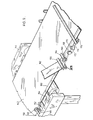
- the device shown in Figure 9 is similar to that shown in Figure 8.
- the web stock 142 is conveyed over framework 144 and over a support 146.
- a glue applicator roll 148 applies glue to an edge 150 of the web 142.
- a device (not shown) is used to plough over the edge 150 in the direction of arrow 152 and rollers are used to lay down and secure the folded over edge portion 154 of the web stock 142.
- the adhesive used is such that the folded over edge portion 154 remains flat after passing between spring loaded pressure rollers 156 and 158.
- the film is of sufficient width and secured to the web 142 in a manner so as to extend beyond edge 160 of the folded over portion 154 such that when the film 162 with pressure sensitive adhesive on its underside passes between the web edge 154 supported by roller 158 and the spring loaded roller 156, it is secured to the web edge and overlaps the edge 160 of the folded over portion of the web stock.
- the film is then wrapped around and onto the undersurface of the web stock in a four-stage process. Having secured a portion of the width of the film 162 to the upper surface of the web stock, the accurate location of the film relative to the web stock is now determined.
- a four inch (10.2 cm) width of film one and a half inches (3.8 cm) of the film width is laid onto and secured to the presented surface of the folder stock.
- the next stage is to fold over the remaining two and a half inches (6.35 cm) of film which is commenced by roller 164 having bevelled face portion 166. Bevelled face 166 bends the film downwardly at an angle relative to the plane of the web stock.
- the next stage in bending the film is provided by vertical roller 168 which bends the film to a 90 degree angle relative to the plane of the web stock.
- the next stage of the fold over is provided by roller 170 having bevelled face 172 which begins to fold the film underneath the web stock at an acute angle relative to the underside of the plane of the web stock.
- the film, as bent under the web stock, can now be passed through spring loaded pressure rollers 174 and 176 to complete the securement of the folded over film to the web stock.
- the overall length of the roller arrangement 178 is sufficient to ensure a smooth wrap around the film without creases therein.
- the web stock is now ready for the next stage in manufacture, namely the die cutting thereof to provide the desired shape to the side of the folder and cut the folder blank from the web stock in a manner which is commonly used in the art.
- a clear film is applied to the web stock a narrower film width may be used because of the nonrequirement of a large colour band.
- a 7.6 cm (three inch) clear film may be used where the film is folded over equally on both surfaces of the web stock to reinforce the edge.
- a coloured band can be provided by having coloured paper on the web stock edge and covered by the Mylar (RTM) film.
- the colour of the paper shows through the clear film to provide a desired colour band.
- the coloured paper may be secured to the Mylar (RTM) film and the paper, in turn, be secured to the folder edge or conversely, the coloured paper may be secured to the folder edge and the Mylar (RTM) film applied over the coloured paper.
- the plastic reinforcing film must, when applied to the paper web stock, reduce the tendency of the tab or edge to be torn from the paper web stock and distribute forces such that creasing and folding of the tab or panel adjacent the tab are reduced.
- Films which are suitable include, polyethylene terephthalate films such as sold by Dupont under Mylar (RTM), "Celanar” (RTM) from Celanese, and "Scotchpar” (RTM) from 3M.
- the film is preferably of a thickness in the approximate range of 0.006 to 0.025 mm (0.25 to about 1 thousandth of an inch) and with advantage from about 0.012 to 0.025 mm (0.5 to 1 thousandth of an inch) and it may usefully be about 0.025 mm (1 thousandth of an inch).
- the thickness of the folder stock is normally in the approximate range of 0.254 to 0.381 mm (0.010 to 0.015 inches).
- Figures 10 through 14 illustrate a variation of the method of manufacturing the product. For this reason, a new numbering scheme will be used.
- the web 300 of paper web stock is advanced from a roll (not shown) and undergoes a number of operations to produce the file folder blank 302 shown in Figure 13 or the modified folder blank 302a shown in Figure 14.
- the difference between the folder blank of Figure 13 and that of Figure 14 is that a portion of the reinforced edge has been removed from the front panel 308 to thereby define an outward extension portion 305 on the back panel 310.
- the reinforced edge 303 has a high tensile strength reinforcing film 312 secured about the straight reinforced edge 303 with a portion of the film extending beyond the reinforced edge to be in direct contact with the portion of the web stock 300 adjacent the reinforced edge. In this way, reinforcement of the file folder adjacent the junction of the reinforced edge 303 and the abutting paper stock is achieved. This serves to distribute localized forces exerted on the outward extension 305 to the file folder and thereby avoid localized deterioration of the extension.
- paper web stock and film are not folded in the center line of the film as it is preferable to have the film extend across the junction of the reinforced edge and the paper web stock to reinforce this and reduce the tendency of this reinforced area to be torn from the remaining body of the web stock.
- the high tensile strength film 312 is secured by an adhesive 311 to one surface of the paper web stock 300 adjacent the edge thereof, in this case to the lower surface of the paper web stock, as the web stock is advanced. This advancement is generally indicated by arrow 320 showing movement of the paper web stock and arrow 321 showing movement of the high tensile strength film with adhesive applied thereto.
- a paper web stock aligning device 322 accurately maintains alignment of the paper web stock as it is being withdrawn from the supply roll.
- One such aligning device is manufactured by G. W. D. Controls Limited and is referred to as a paper stock guide.
- This apparatus accurately maintains the edge of the paper web stock and therefore a manual aligning roller generally shown as 330 in Figure 11 can be used to align the high tensile strength film with the edge of the paper web stock to assure placement of the film adjacent the edge of the web stock.
- the high tensile strength film 312 is applied to the lower surface of the web stock 300 and is retained on the web stock as it is passed between pressure rollers 340 and 341. This assures the pressure sensitive adhesive 311 firmly bonds the high tensile strength film to the lower surface of the paper web stock.
- the high tensile strength film is not driven but merely advanced by the web stock.
- a further adhesive 314 is then applied adjacent the edge of the paper web stock and is used to secure the paper web stock portions 316 and 318 as shown in Figure 13.
- the web stock is passed through a number of folding rollers generally designated as 350 to fold the paper web stock upon itself and subsequently pass the folded web stock through pressure rollers 352 and 354 in order to strongly adhere the paper web stock portions 316 and 318.
- the paper web stock is passed through a number of cutting or blanking operations to form folder blanks generally as shown in Figure 13 and Figure 14.
- a fold line 370 has been produced on the folder blank 302 and 302a to thereby define front and back panels of the file folder.
- a file folder having a laterally extending portion 305 is produced suitable for use in lateral filing.
- Paper web stock is very susceptible to wear and separation of the individual layers thereof which substantially weakens the overall strength of the web stock. This problem is particularly acute at areas of high stress which are subject to damage such as the portion of the file folder which extends beyond the panels of the folder to present a surface to which labels can be applied for identifying of the file folder. As such, the label identifying portion is prone to wear and often will tear from the body of the folder.
- a high tensile strength film either side of the paper substrate, and in a manner to bridge the transition between the reinforced edge and the body of the file folder, the tendency of the paper stock to separate is reduced as the high tensile strength film reinforces the area and limits the separation of the individual layers.
Landscapes
- Engineering & Computer Science (AREA)
- Manufacturing & Machinery (AREA)
- Mechanical Engineering (AREA)
- Sheet Holders (AREA)
- Pharmaceuticals Containing Other Organic And Inorganic Compounds (AREA)
- Radiation-Therapy Devices (AREA)
- Medicines Containing Antibodies Or Antigens For Use As Internal Diagnostic Agents (AREA)
- Folding Of Thin Sheet-Like Materials, Special Discharging Devices, And Others (AREA)
- Laminated Bodies (AREA)
Claims (17)
Priority Applications (1)
| Application Number | Priority Date | Filing Date | Title |
|---|---|---|---|
| AT83306584T ATE58678T1 (de) | 1982-10-29 | 1983-10-28 | Aktendeckel mit verstaerkten raendern und verfahren zu dessen herstellung. |
Applications Claiming Priority (2)
| Application Number | Priority Date | Filing Date | Title |
|---|---|---|---|
| CA414537 | 1982-10-29 | ||
| CA000414537A CA1221598A (en) | 1982-10-29 | 1982-10-29 | Reinforced file folder panel edges and method |
Publications (3)
| Publication Number | Publication Date |
|---|---|
| EP0107519A2 EP0107519A2 (de) | 1984-05-02 |
| EP0107519A3 EP0107519A3 (en) | 1986-01-08 |
| EP0107519B1 true EP0107519B1 (de) | 1990-11-28 |
Family
ID=4123849
Family Applications (1)
| Application Number | Title | Priority Date | Filing Date |
|---|---|---|---|
| EP83306584A Expired - Lifetime EP0107519B1 (de) | 1982-10-29 | 1983-10-28 | Aktendeckel mit verstärkten Rändern und Verfahren zu dessen Herstellung |
Country Status (6)
| Country | Link |
|---|---|
| EP (1) | EP0107519B1 (de) |
| JP (1) | JPS59135193A (de) |
| AT (1) | ATE58678T1 (de) |
| AU (1) | AU563833B2 (de) |
| CA (1) | CA1221598A (de) |
| DE (1) | DE3382027D1 (de) |
Cited By (1)
| Publication number | Priority date | Publication date | Assignee | Title |
|---|---|---|---|---|
| US10017002B2 (en) | 2012-05-21 | 2018-07-10 | ACCO Brands Corporation | Reinforced pocket device |
Family Cites Families (15)
| Publication number | Priority date | Publication date | Assignee | Title |
|---|---|---|---|---|
| US2052623A (en) * | 1932-06-10 | 1936-09-01 | Yawman & Erbe Mfg Co | Folder |
| US2712342A (en) * | 1946-12-05 | 1955-07-05 | M B Claff & Sons Inc | Laminating machine for producing composite webs of paper |
| FR1083320A (fr) * | 1952-09-13 | 1955-01-07 | Machine à coller des bandes sur des objets | |
| FR1252460A (fr) * | 1960-03-29 | 1961-01-27 | Manuf Normande De Papeterie | Perfectionnements aux répertoires alphabétiques ou articles analogues |
| DE1198663B (de) * | 1963-06-06 | 1965-08-12 | Weyerhaeuser Co | Verfahren zum Herstellen von zu Verpackungs-behaeltern weiterverarbeitbaren Zuschnitten mit Kantenversteifung |
| DE1948594U (de) * | 1966-04-06 | 1966-10-27 | Kalle Ag | Vorrichtung zum aufbringen einer randverstaerkung an technischen zeichnungen. |
| GB1072130A (en) * | 1968-09-13 | 1967-06-14 | Hardinge Brothers Inc | Improvements in machine tools |
| JPS5323324B2 (de) * | 1971-12-27 | 1978-07-14 | ||
| FR2300685A1 (fr) * | 1975-02-14 | 1976-09-10 | Chevalerias Sa | Dossier suspendu destine notamment aux armoires de classement |
| JPS5258316A (en) * | 1975-11-08 | 1977-05-13 | Matsushita Electric Ind Co Ltd | Tv receiver |
| US4204639A (en) * | 1977-03-09 | 1980-05-27 | Datafile Limited | Coded label |
| US4175476A (en) * | 1978-03-27 | 1979-11-27 | H. G. Weber & Co., Inc. | Method and apparatus for forming reinforced top file folders |
| US4240848A (en) * | 1978-07-05 | 1980-12-23 | Datafile Limited | System for alphabetically labelling articles |
| FR2477504A1 (fr) * | 1980-03-07 | 1981-09-11 | Habilclass | Dispositif pour le pliage et le collage de bandes adhesives sur des documents plats |
| US4445711A (en) * | 1980-10-02 | 1984-05-01 | Cunningham Walter F | Color-coded numeric or alphabetic filing system |
-
1982
- 1982-10-29 CA CA000414537A patent/CA1221598A/en not_active Expired
-
1983
- 1983-10-28 EP EP83306584A patent/EP0107519B1/de not_active Expired - Lifetime
- 1983-10-28 AT AT83306584T patent/ATE58678T1/de active
- 1983-10-28 DE DE8383306584T patent/DE3382027D1/de not_active Expired - Fee Related
- 1983-10-28 JP JP58201137A patent/JPS59135193A/ja active Pending
- 1983-10-31 AU AU20814/83A patent/AU563833B2/en not_active Expired
Cited By (1)
| Publication number | Priority date | Publication date | Assignee | Title |
|---|---|---|---|---|
| US10017002B2 (en) | 2012-05-21 | 2018-07-10 | ACCO Brands Corporation | Reinforced pocket device |
Also Published As
| Publication number | Publication date |
|---|---|
| JPS59135193A (ja) | 1984-08-03 |
| ATE58678T1 (de) | 1990-12-15 |
| AU2081483A (en) | 1984-05-03 |
| CA1221598A (en) | 1987-05-12 |
| EP0107519A2 (de) | 1984-05-02 |
| AU563833B2 (en) | 1987-07-23 |
| EP0107519A3 (en) | 1986-01-08 |
| DE3382027D1 (de) | 1991-01-10 |
Similar Documents
| Publication | Publication Date | Title |
|---|---|---|
| US4749121A (en) | Reinforced file folder | |
| US4588463A (en) | Method of producing a reinforced file folder | |
| US4986868A (en) | Method of making an intermediate blank for identification card or the like | |
| US5466013A (en) | Card intermediate and method | |
| EP0232054B1 (de) | Etiketten und ihre Fertigung | |
| US6413604B1 (en) | Multiple layer labels and methods | |
| US4696843A (en) | Differential pressure sensitive adhesive joined business form | |
| US6669804B2 (en) | Label having tab member and methods for forming, applying and using the same | |
| US5458374A (en) | Universal non-jamming multi-ply multi-fold outsert with compact peripheral edges (and related method) | |
| KR19990029078A (ko) | 라벨 및 그의 제조방법 | |
| JPS61164926A (ja) | 包装、包装積層材料および包装方法 | |
| CA2376836A1 (en) | Paperboard cartons with laminated reinforcing ribbons and method of making same | |
| US6533325B1 (en) | Integral card and method of making | |
| US4520055A (en) | Split label index tab | |
| US4690720A (en) | Method of manufacturing multilayer labels and apparatus therefor | |
| US4685610A (en) | Container and method of making a container with integral bottom panel and side panels | |
| US5030189A (en) | Method of making envelope with tear line formed by ultrasonic energy | |
| CA1197155A (en) | Reinforced file folder and method | |
| EP0386399A1 (de) | Behälterverpackung | |
| US4347274A (en) | Visible indexes | |
| EP0597609B1 (de) | Kombiniertes Anhänger- und Etikettenblatt und Verfahren zur Herstellung desselben | |
| CN102015321A (zh) | 包括以共面方式组装的至少两个平坦的部分打印载体的打印载体、部分打印载体及其制造方法 | |
| CA1216486A (en) | Reinforced file folder and method | |
| EP0107519A2 (de) | Aktendeckel mit verstärkten Rändern und Verfahren zu dessen Herstellung | |
| JP4167016B2 (ja) | ラベルを製造する方法及び装置並びにこの方法で得られるラベル |
Legal Events
| Date | Code | Title | Description |
|---|---|---|---|
| PUAI | Public reference made under article 153(3) epc to a published international application that has entered the european phase |
Free format text: ORIGINAL CODE: 0009012 |
|
| AK | Designated contracting states |
Designated state(s): AT BE CH DE FR GB IT LI LU NL SE |
|
| PUAL | Search report despatched |
Free format text: ORIGINAL CODE: 0009013 |
|
| AK | Designated contracting states |
Designated state(s): AT BE CH DE FR GB IT LI LU NL SE |
|
| 17P | Request for examination filed |
Effective date: 19860703 |
|
| 17Q | First examination report despatched |
Effective date: 19871207 |
|
| RAP1 | Party data changed (applicant data changed or rights of an application transferred) |
Owner name: WRIGHT LINE OF CANADA LTD. |
|
| GRAA | (expected) grant |
Free format text: ORIGINAL CODE: 0009210 |
|
| AK | Designated contracting states |
Kind code of ref document: B1 Designated state(s): AT BE CH DE FR GB IT LI LU NL SE |
|
| PG25 | Lapsed in a contracting state [announced via postgrant information from national office to epo] |
Ref country code: SE Effective date: 19901128 Ref country code: LI Effective date: 19901128 Ref country code: CH Effective date: 19901128 Ref country code: BE Effective date: 19901128 Ref country code: AT Effective date: 19901128 |
|
| REF | Corresponds to: |
Ref document number: 58678 Country of ref document: AT Date of ref document: 19901215 Kind code of ref document: T |
|
| REF | Corresponds to: |
Ref document number: 3382027 Country of ref document: DE Date of ref document: 19910110 |
|
| ITF | It: translation for a ep patent filed | ||
| ET | Fr: translation filed | ||
| REG | Reference to a national code |
Ref country code: CH Ref legal event code: PL |
|
| PGFP | Annual fee paid to national office [announced via postgrant information from national office to epo] |
Ref country code: SE Payment date: 19910918 Year of fee payment: 9 |
|
| PLBE | No opposition filed within time limit |
Free format text: ORIGINAL CODE: 0009261 |
|
| STAA | Information on the status of an ep patent application or granted ep patent |
Free format text: STATUS: NO OPPOSITION FILED WITHIN TIME LIMIT |
|
| 26N | No opposition filed | ||
| ITTA | It: last paid annual fee | ||
| PGFP | Annual fee paid to national office [announced via postgrant information from national office to epo] |
Ref country code: LU Payment date: 19930924 Year of fee payment: 11 |
|
| PGFP | Annual fee paid to national office [announced via postgrant information from national office to epo] |
Ref country code: NL Payment date: 19931031 Year of fee payment: 11 |
|
| EPTA | Lu: last paid annual fee | ||
| PG25 | Lapsed in a contracting state [announced via postgrant information from national office to epo] |
Ref country code: LU Free format text: LAPSE BECAUSE OF NON-PAYMENT OF DUE FEES Effective date: 19941028 |
|
| PG25 | Lapsed in a contracting state [announced via postgrant information from national office to epo] |
Ref country code: NL Effective date: 19950501 |
|
| NLV4 | Nl: lapsed or anulled due to non-payment of the annual fee | ||
| PGFP | Annual fee paid to national office [announced via postgrant information from national office to epo] |
Ref country code: GB Payment date: 20001018 Year of fee payment: 18 |
|
| PGFP | Annual fee paid to national office [announced via postgrant information from national office to epo] |
Ref country code: FR Payment date: 20001026 Year of fee payment: 18 |
|
| PGFP | Annual fee paid to national office [announced via postgrant information from national office to epo] |
Ref country code: DE Payment date: 20001222 Year of fee payment: 18 |
|
| PG25 | Lapsed in a contracting state [announced via postgrant information from national office to epo] |
Ref country code: GB Free format text: LAPSE BECAUSE OF NON-PAYMENT OF DUE FEES Effective date: 20011028 |
|
| REG | Reference to a national code |
Ref country code: GB Ref legal event code: IF02 |
|
| GBPC | Gb: european patent ceased through non-payment of renewal fee |
Effective date: 20011028 |
|
| PG25 | Lapsed in a contracting state [announced via postgrant information from national office to epo] |
Ref country code: FR Free format text: LAPSE BECAUSE OF NON-PAYMENT OF DUE FEES Effective date: 20020628 |
|
| PG25 | Lapsed in a contracting state [announced via postgrant information from national office to epo] |
Ref country code: DE Free format text: LAPSE BECAUSE OF NON-PAYMENT OF DUE FEES Effective date: 20020702 |
|
| REG | Reference to a national code |
Ref country code: FR Ref legal event code: ST |