EP0107546A1 - Paumelle réglable en hauteur - Google Patents
Paumelle réglable en hauteur Download PDFInfo
- Publication number
- EP0107546A1 EP0107546A1 EP83401885A EP83401885A EP0107546A1 EP 0107546 A1 EP0107546 A1 EP 0107546A1 EP 83401885 A EP83401885 A EP 83401885A EP 83401885 A EP83401885 A EP 83401885A EP 0107546 A1 EP0107546 A1 EP 0107546A1
- Authority
- EP
- European Patent Office
- Prior art keywords
- hinge
- male plug
- collar
- hinge portion
- axial
- Prior art date
- Legal status (The legal status is an assumption and is not a legal conclusion. Google has not performed a legal analysis and makes no representation as to the accuracy of the status listed.)
- Granted
Links
- 238000000034 method Methods 0.000 claims description 5
- 239000004952 Polyamide Substances 0.000 claims description 3
- 230000005489 elastic deformation Effects 0.000 claims description 3
- 229920002647 polyamide Polymers 0.000 claims description 3
- 239000000843 powder Substances 0.000 claims description 3
- 238000010079 rubber tapping Methods 0.000 abstract 3
- 239000000428 dust Substances 0.000 description 3
- 239000004519 grease Substances 0.000 description 2
- 230000003647 oxidation Effects 0.000 description 2
- 238000007254 oxidation reaction Methods 0.000 description 2
- 230000002093 peripheral effect Effects 0.000 description 2
- 230000006835 compression Effects 0.000 description 1
- 238000007906 compression Methods 0.000 description 1
- 238000010276 construction Methods 0.000 description 1
- 238000000151 deposition Methods 0.000 description 1
- 210000002445 nipple Anatomy 0.000 description 1
- XLYOFNOQVPJJNP-UHFFFAOYSA-N water Substances O XLYOFNOQVPJJNP-UHFFFAOYSA-N 0.000 description 1
Images

Classifications
-
- E—FIXED CONSTRUCTIONS
- E05—LOCKS; KEYS; WINDOW OR DOOR FITTINGS; SAFES
- E05D—HINGES OR SUSPENSION DEVICES FOR DOORS, WINDOWS OR WINGS
- E05D5/00—Construction of single parts, e.g. the parts for attachment
- E05D5/10—Pins, sockets or sleeves; Removable pins
- E05D5/12—Securing pins in sockets, movably or not
- E05D5/121—Screw-threaded pins
-
- E—FIXED CONSTRUCTIONS
- E05—LOCKS; KEYS; WINDOW OR DOOR FITTINGS; SAFES
- E05D—HINGES OR SUSPENSION DEVICES FOR DOORS, WINDOWS OR WINGS
- E05D7/00—Hinges or pivots of special construction
- E05D7/0009—Adjustable hinges
- E05D7/0018—Adjustable hinges at the hinge axis
- E05D7/0027—Adjustable hinges at the hinge axis in an axial direction
-
- E—FIXED CONSTRUCTIONS
- E05—LOCKS; KEYS; WINDOW OR DOOR FITTINGS; SAFES
- E05D—HINGES OR SUSPENSION DEVICES FOR DOORS, WINDOWS OR WINGS
- E05D11/00—Additional features or accessories of hinges
- E05D11/0054—Covers, e.g. for protection
- E05D2011/0072—Covers, e.g. for protection for the gap between hinge parts
-
- E—FIXED CONSTRUCTIONS
- E05—LOCKS; KEYS; WINDOW OR DOOR FITTINGS; SAFES
- E05Y—INDEXING SCHEME ASSOCIATED WITH SUBCLASSES E05D AND E05F, RELATING TO CONSTRUCTION ELEMENTS, ELECTRIC CONTROL, POWER SUPPLY, POWER SIGNAL OR TRANSMISSION, USER INTERFACES, MOUNTING OR COUPLING, DETAILS, ACCESSORIES, AUXILIARY OPERATIONS NOT OTHERWISE PROVIDED FOR, APPLICATION THEREOF
- E05Y2900/00—Application of doors, windows, wings or fittings thereof
- E05Y2900/10—Application of doors, windows, wings or fittings thereof for buildings or parts thereof
- E05Y2900/13—Type of wing
- E05Y2900/132—Doors
Definitions
- the present invention relates to a hinge adjustable in height.
- Hinges are already known comprising, between a lower hinge, secured to a fixed part, and an upper hinge, secured to a movable part, a male plug having a collar at an intermediate point of its length, this collar defining a shoulder. cooperating with a bearing surface of an axial housing provided in the hinge, and, below this collar, a threaded rod which is screwed into an axial thread provided in the hinge.
- the hinge is drilled right through an axial hole essentially constituting the housing of the cylindrical part of the male plug located above the intermediate collar.
- This axial hole opens into the upper front face of the hinge and makes it possible to rotate, by means of a tool such as a screwdriver, the male plug, which ensures the adjustment, at the desired height, of the mobile hinge by relative to the fixed hinge, that is to say in fact the position of a door or window leaf, relative to the fixed frame.
- a tool such as a screwdriver
- the male plug which ensures the adjustment, at the desired height, of the mobile hinge by relative to the fixed hinge, that is to say in fact the position of a door or window leaf, relative to the fixed frame.
- the present invention relates to improvements made to a hinge of this type in order to improve its tightness and to allow the use of style vases of the same type screwed at the two ends of the hinge.
- this height-adjustable hinge comprising a hinge and a hinge secured to members allowing them to be fixed respectively to fixed and movable parts, and a male plug ensuring the connection between them and constituting an axis of articulation
- this male plug comprising a cylindrical upper part engaging in a housing constituted by an axial hole passing right through the body of the hinge, an intermediate collar delimiting, with the cylindrical upper part, a shoulder cooperating with a bearing surface of said housing of the hinge, and a threaded lower part screwed into an axial thread drilled in the hinge, the hinge having, on its upper face, a smooth recess of diameter equal to that of the neck let of the male plug and in which this collar is more or less engaged depending on the height adjustment, this recess being extended downwards by the axial thread in which is screwed the threaded rod of the male plug and which opens into the face lower hinge, characterized in that the lower end part of the axial thread of the hinge and the upper end tapped part of the central housing of the hinge
- the hinge according to the invention offers several advantages. Because the collar of the male plug is permanently embedded, partially, in the recess provided in the upper face of the hinge, a perfect seal is obtained with regard to dust and other detritus which can be deposited on the door hinges , windows, shutters and shutters of construction sites, when the opening is unfolded, which is often the case. In addition, the threaded rod of the male plug is completely hidden inside the hinge, regardless of the height adjustment, so that it is perfectly protected against any oxidation.
- the hinge according to the invention allows the same style vase to be used at each end of the hinge, which thus simplifies the keeping of stocks at hardware stores and user companies.
- the hinges can be delivered without style vases, the upper holes of the hinge and lower of the hinge being closed by identical buckles each having, in its central part, a threaded stud. These hinges can later receive any style vase, according to the owner's taste, these style vases being screwed in place of the two closure caps.
- the threading of the threaded rod of the male plug is treated by a self-braking process, which avoids having to use an additional compression spring to brake the threaded rod.
- the thread of this rod threaded is covered with a polyamide powder having elastic deformation properties, which provides effective protection against loosening of the male plug.
- the hinge according to the invention shown in the drawing essentially comprises three main parts, namely a lower hinge 1, an upper hinge 2 and a male plug 3 ensuring the connection between the two preceding elements.
- the hinge 1 comprises a body 4 of generally cylindrical shape which is integral with a member allowing its fixing on a fixed part.
- This member can be for example a radial threaded rod 5 ( Figure 1) or even a plate pierced with holes for the passage of fixing screws.
- the lower orifice of the thread 6 is closed by a plug 3 of diameter equal to that of the body 4 and which has, in its central part, a threaded stud 9 which is screwed into the lower end of the thread 6.
- the male plug 3 comprises a cylindrical upper part 10 ending in an upper front face in which is provided a diametrical notch 11 making it possible to rotate the male plug 3 by means of a screwdriver.
- a collar 12 of larger diameter which is equal to the internal diameter of the recess 7 of the hinge 1. This collar 10 defines with the cylindrical part 10 a shoulder 13.
- the male plug 3 comprises, below the collar 12, a threaded rod 14 which screws into the axial thread 6 of the body 4.
- the hinge 2 comprises a cylindrical body 15 which is integral with a fixing member on a movable part, such as a radial threaded rod 16.
- the body 15 of the hinge 2 is pierced right through with an axial hole which has several parts of different diameters, namely an upper part 17 of diameter corresponding to that of the cylindrical upper part 10 of the plug 3, then an intermediate part 18 of diameter corresponding to that of the collar 12 and connected to the upper part 17 by a bearing surface 19 and finally a lower part 20 of diameter equal to or slightly greater than the external diameter of the body 4 of the hinge 1.
- This part 20 of large diameter defines a peripheral skirt 21 which covers the upper part of the body 4 of the hinge 1.
- the body 15 of the hinge 2 has a tapped hole 22 separated from the axial hole 17 by an annular internal lip 23.
- This plug 25 is provided, as is also the case with the lower plug 8, with a diametrical slot 26 making it possible to block or unblock it by means of a screwdriver.
- This plug 25 constitutes a grease plug and it delimits, between itself and the upper end of the plug 3, a volume forming a grease reservoir. This plug 25 also opposes any entry of water or dust inside the hinge.
- the lower 8 and upper 25 plugs can be replaced by strictly identical style vases 27.
- Each of these style vases has, on its front support surface, an axial threaded stud 28 which is screwed either in the lower end portion of the thread 6 of the hinge 1 or in the upper threaded hole 22 of the hinge 2.
- the style vases 27 can have a flat front end face or else they can comprise a peripheral skirt which covers the lower extreme part of the hinge 1 and the upper extreme part of the hinge 2.
- the hinge according to the invention is further characterized in that the threaded rod 14 is treated by a self-braking process consisting in depositing on the thread of this rod a polyamide powder having elastic deformation properties ensuring effective protection against loosening of the male plug 3.
- a self-braking process consisting in depositing on the thread of this rod a polyamide powder having elastic deformation properties ensuring effective protection against loosening of the male plug 3.
Landscapes
- Engineering & Computer Science (AREA)
- Mechanical Engineering (AREA)
- Pivots And Pivotal Connections (AREA)
- Hinges (AREA)
- Hinge Accessories (AREA)
- Fluid-Damping Devices (AREA)
- Chair Legs, Seat Parts, And Backrests (AREA)
Abstract
Description
- La présente invention concerne une paumelle réglable en hauteur.
- On connaît déjà des paumelles comportant, entre un gond inférieur, solidaire d'une partie fixe, et une penture supérieure, solidaire d'une partie mobile, une fiche mâle présentant un collet en un point intermédiaire de sa longueur, ce collet définissant un épaulement coopérant avec une portée d'un logement axial prévu dans la penture, et, en dessous de ce collet, une tige filetée qui est vissée dans un taraudage axial prévu dans le gond. La penture est percée de part en part d'un trou axial constituant pour l'essentiel le logement de la partie cylindrique de la fiche mâle située au dessus du collet intermédiaire. Ce trou axial débouche dans la face frontale supérieure de la penture et permet de faire tourner, au moyen d'un outil tel qu'un tournevis, la fiche mâle, ce qui assure le réglage, à la hauteur désirée, de la penture mobile par rapport au gond fixe, c'est-à-dire en fait la position d'un vantail de porte ou fenêtre, par rapport au cadre fixe. Un telle paumelle réglable en hauteur est décrite dans le brevet français N° 77 33385.
- La présente invention concerne des perfectionnements apportés à une paumelle de ce type dans le but d'améliorer son étanchéité et de permettre d'utiliser des vases de style d'un même type se vissant aux deux extrémités de la paumelle.
- A cet effet cette paumelle réglable en hauteur comportant un gond et une penture solidaires d'organes permettant leur fixation respectivement sur des parties fixe et mobile, et une fiche mâle assurant la liaison entre eux et constituant un axe d'articulation, cette fiche mâle comportant une partie supérieure cylindrique s'engageant dans un logement constitué par un trou axial traversant de part en part le corps de la penture, un collet intermédiaire délimitant, avec la partie supérieure cylindrique, un épaulement coopérant avec une portée dudit logement de la penture, et une partie inférieure filetée vissée dans un taraudage axial percé dans le gond, le gond présentant, dans sa face supérieure, un chambrage lisse de diamètre égal à celui du collet de la fiche mâle et dans lequel ce collet est plus ou moins engagé en fonction du réglage en hauteur, ce chambrage étant prolongé vers le bas par le taraudage axial dans lequel est vissée la tige filetée de la fiche mâle et qui débouche dans la face inférieure du gond, caractérisée en ce que la partie extrême inférieure du taraudage axial du gond et la partie extrême supérieure taraudée du logement central de la penture sont destinées à recevoir des tétons filetés de bouchons de fermeture ou de vases de style identiques.
- La paumelle suivant l'invention offre plusieurs avantages. Du fait que le collet de la fiche mâle est encastré en permanence, partiellement, dans le chambrage prévu dans la face supérieure du gond, on obtient une étanchéité parfaite à l'égard des poussières et autres détritus qui peuvent se déposer sur les paumelles des portes, fenêtres, volets et persiennes des chantiers de construction, lorsque les ouvrants sont dégondés, ce qui est souvent le cas. En outre la tige filetée de la fiche mâle est totalement cachée à l'intérieur du gond, quel que soit le réglage en hauteur, si bien qu'ele est parfaitement protégée à l'égard de toute oxydation.
- Un autre avantage offert par la paumelle suivant l'invention est qu'elle permet d'employer le même vase de style à chaque bout de la paumelle, ce qui simplifie ainsi la tenue des stocks chez les quincaillers et les entreprises utilisatrices. Les paumelles peuvent être livrées sans vases de style, les orifices supérieur de la penture et inférieur du gond étant obturés par des bouclions identiques présentant chacun, dans sa partie centrale, un téton fileté. Ces paumelles peuvent recevoir ultérieurement n'importe quel vase de style, suivant le goût du propriétaire, ces vases de style étant vissés h la place des deux bouchons de fermeture.
- Suivant une caractéristique complémentaire de l'invention le filetage de la tige filetée de la fiche mâle est traité par un procédé auto-freinant, ce qui évite d'avoir à utiliser un ressort de compression additionnel pour freiner la tige filetée. De préférence le filetage de cette tige filetée est recouvert d'une poudre polyamide ayant des propriétés de déformation élastique, ce qui assure une protection efficace contre le desserrage de la fiche mâle.
- On décrira ci-après, à titre d'exemple non limitatif, une forme d'exécution de la présente invention, en référence au dessin annexé sur lequel
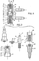
- La figure 1 est une vue en coupe axiale d'une paumelle suivant l'invention dont la penture et le gond sont tous les deux coiffés d'un bouchon de fermeture.
- La figure 2 est vue éclatée des divers éléments constitutifs de la paumelle suivant l'invention, une partie de ces éléments étant représentée en coupe axiale et l'autre partie en élévation.
- La figure 3 est une vue en élévation, partiellement en coupe axiale, d'une paumelle munie de deux vases de style.
- La paumelle suivant l'invention représentée sur le dessin comprend essentiellement trois parties principales à savoir un gond inférieur 1, une penture supérieure 2 et une fiche mâle 3 assurant la liaison entre les deux éléments précédents.
- Le gond 1 comporte un corps 4 de forme générale cylindrique qui est solidaire d'un organe permettant sa fixation sur une partie fixe. Cet organe peut être par exemple une tige filetée radiale 5 (Figure 1) ou bien encore une platine percée de trous pour le passage de vis de fixation.
- Dans la partie médiane et inférieure du corps 4 est percé un taraudage axial 6 qui débouche dans la face frontale inférieure 4a du corps 4. Ce taraudage 6 se raccorde, à son extrémité supérieure, à un chambrage 7 de plus grand diamètre, qui débouche lui-même dans la face frontale supérieure 4b du corps 4.
- L'orifice inférieur du taraudage 6 est obturé par un bouchon 3 de diamètre égal à celui du corps 4 et qui présente, dans sa partie centrale, un téton fileté 9 qui est vissé dans la partie extrême inférieure du taraudage 6.
- La fiche mâle 3 comporte une partie supérieure cylindrique 10 se terminant par une face frontale supérieure dans laquelle est prévue une encoche diamétrale 11 permettant de faire tourner la fiche mâle 3 au moyen d'un tournevis. En dessous de la partie supérieure cylindrique 10 se trouve un collet 12 de plus grand diamètre qui est égal au diamètre interne du chambrage 7 du gond 1. Ce collet 10 délimite avec la partie cylindrique 10 un épaulement 13. Enfin la fiche mâle 3 comporte, en dessous du collet 12, une tige filetée 14 qui se visse dans le taraudage axial 6 du corps 4.
- La penture 2 comporte un corps 15 cylindrique qui est solidaire d'un organe de fixation sur une partie mobile, tel qu'une tige filetée radiale 16. Le corps 15 de la penture 2 est percé de part en part d'un trou axial qui présente plusieurs parties de diamètres différents à savoir une partie supérieure 17 de diamètre correspondant à celui de la partie supérieure cylindrique 10 de la fiche mâle 3, puis une partie intermédiaire 18 de diamètre correspondant à celui du collet 12 et raccordée à la partie supérieure 17 par une portée 19 et enfin une partie inférieure 20 de diamètre égal ou légèrement supérieur au diamètre externe du corps 4 du gond 1. Cette partie 20 de grand diamètre délimite une jupe périphérique 21 qui coiffe la partie supérieure du corps 4 du gond 1.
- A sa partie supérieure le corps 15 de la penture 2 présente un trou taraudé 22 séparé du trou axial 17 par une lèvre interne annulaire 23. Dans ce trou taraudé 22 est vissé un téton fileté 24 d'un bouchon de fermeture 25 de même diamètre que le corps 15 et qui s'applique contre la face frontale supérieure de celui-ci. Ce bouchon 25 est pourvu, de même d'ailleurs que le bouchon inférieur 8, d'une fente diamétrale 26 permettant de le bloquer ou de le débloquer au moyen d'un tournevis. Ce bouchon 25 constitue un bouchon de graissage et il délimite, entre lui-même et l'extrémité supérieure de la fiche mâle 3, un volume formant réservoir de graisse. Ce bouchon 25 s'oppose par ailleurs à toute entrée d'eau ou de poussières à l'intérieur de la paumelle.
- On voit, d'après la description qui précéde, que le collet 12 de la fiche mâle 3 est encastré partiellement dans le chambrage 7 du corps 4 du gond 1, quel que soit le réglage en hauteur de la paumelle. Du fait de cet encastrement étroit, on évite ainsi que des poussières ou des détritus viennent se loger entre la fiche mâle 3 et le corps 4 du gond 1. En outre la tige inférieure filetée 14 de la fiche mâle 3 est protégée à l'égard de l'oxydation.
- Les bouchons inférieur 8 et supérieur 25 peuvent être remplacés par des vases de style 27 rigoureusement identiques. Chacun de ces vases de style présente, sur sa face frontale d'appui, un téton fileté axial 28 qui vient se visser soit dans la partie extrême inférieure du taraudage 6 du gond 1 soit dans le trou taraudé supérieur 22 de la penture 2.
- Les vases de style 27 peuvent présenter une face frontale d'appui plane ou bien encore ils peuvent comporter une jupe périphérique venant coiffer la partie extrême inférieure du gond 1 et la partie extrême supérieure de la penture 2.
- La paumelle suivant l'invention est en outre caractérisée en ce que la tige filetée 14 est traitée par un procédé auto-freinant consistqnt h déposer sur le filetage de cette tige une poudre polyamide ayant des propriétés de déformation élastique assurant une protection efficace contre le desserrage de la fiche mâle 3. Un tel procédé pouvant être utilisé à cet effet est connu sous le nom de "ESLOK". Naturellement on pourrait également employer tout autre procédé similaire.
Claims (3)
Priority Applications (1)
| Application Number | Priority Date | Filing Date | Title |
|---|---|---|---|
| AT83401885T ATE22591T1 (de) | 1982-09-27 | 1983-09-27 | Hoehenverstellbares scharnierband. |
Applications Claiming Priority (2)
| Application Number | Priority Date | Filing Date | Title |
|---|---|---|---|
| FR8216213A FR2533615B1 (fr) | 1982-09-27 | 1982-09-27 | Paumelle reglable en hauteur |
| FR8216213 | 1982-09-27 |
Publications (2)
| Publication Number | Publication Date |
|---|---|
| EP0107546A1 true EP0107546A1 (fr) | 1984-05-02 |
| EP0107546B1 EP0107546B1 (fr) | 1986-10-01 |
Family
ID=9277756
Family Applications (1)
| Application Number | Title | Priority Date | Filing Date |
|---|---|---|---|
| EP83401885A Expired EP0107546B1 (fr) | 1982-09-27 | 1983-09-27 | Paumelle réglable en hauteur |
Country Status (4)
| Country | Link |
|---|---|
| EP (1) | EP0107546B1 (fr) |
| AT (1) | ATE22591T1 (fr) |
| DE (1) | DE3366615D1 (fr) |
| FR (1) | FR2533615B1 (fr) |
Cited By (2)
| Publication number | Priority date | Publication date | Assignee | Title |
|---|---|---|---|---|
| GB2184776A (en) * | 1985-10-18 | 1987-07-01 | Highland Bond Pty Ltd | Adjustable hinge |
| GB2393480A (en) * | 2002-09-28 | 2004-03-31 | Window Fab & Fixing Supplies | Adjustable pin hinge |
Families Citing this family (4)
| Publication number | Priority date | Publication date | Assignee | Title |
|---|---|---|---|---|
| IT1220037B (it) * | 1987-07-20 | 1990-06-06 | Otalv Spa | Cerniera regolabile su tre assi particolarmente per serramenti |
| FR2752009A1 (fr) | 1996-08-05 | 1998-02-06 | Laurent Gilbert | Paumelle a reglage elastique, son utilisation pour le montage d'un panneau rotatif et bloc-porte la comportant |
| DE10044208B4 (de) * | 2000-09-07 | 2006-08-31 | Alfred Bopp | Türband für Holz- und Metallzargen |
| US7240400B2 (en) * | 2003-10-23 | 2007-07-10 | Brent Bonham | Vertical and horizontal adjustable hinge assembly |
Citations (8)
| Publication number | Priority date | Publication date | Assignee | Title |
|---|---|---|---|---|
| FR347872A (fr) * | 1904-11-12 | 1905-03-25 | Paul Gruenwald | Penture de portes ou fenetres, réglable en hauteur |
| FR2034401A1 (fr) * | 1969-03-27 | 1970-12-11 | Deckmyn Louis | |
| FR2120971A7 (fr) * | 1970-12-28 | 1972-08-18 | Omnitechnic Gmbh | |
| FR2215828A1 (fr) * | 1973-04-06 | 1974-08-23 | Comercial Calrower Sl | |
| US3896760A (en) * | 1972-12-13 | 1975-07-29 | Usm Corp | Apparatus for making self-locking internally threaded articles |
| US4285378A (en) * | 1976-11-29 | 1981-08-25 | The Oakland Corporation | Thread lock |
| FR2479884A1 (fr) * | 1980-04-02 | 1981-10-09 | Laurent Solange | Perfectionnements apportes aux paumelles reglables en hauteur |
| DE3042257A1 (de) * | 1980-07-30 | 1982-03-18 | Walter 8903 Birmensdorf Pfäffli | Tuerband mit verstellmoeglichkeit |
-
1982
- 1982-09-27 FR FR8216213A patent/FR2533615B1/fr not_active Expired
-
1983
- 1983-09-27 EP EP83401885A patent/EP0107546B1/fr not_active Expired
- 1983-09-27 DE DE8383401885T patent/DE3366615D1/de not_active Expired
- 1983-09-27 AT AT83401885T patent/ATE22591T1/de active
Patent Citations (8)
| Publication number | Priority date | Publication date | Assignee | Title |
|---|---|---|---|---|
| FR347872A (fr) * | 1904-11-12 | 1905-03-25 | Paul Gruenwald | Penture de portes ou fenetres, réglable en hauteur |
| FR2034401A1 (fr) * | 1969-03-27 | 1970-12-11 | Deckmyn Louis | |
| FR2120971A7 (fr) * | 1970-12-28 | 1972-08-18 | Omnitechnic Gmbh | |
| US3896760A (en) * | 1972-12-13 | 1975-07-29 | Usm Corp | Apparatus for making self-locking internally threaded articles |
| FR2215828A1 (fr) * | 1973-04-06 | 1974-08-23 | Comercial Calrower Sl | |
| US4285378A (en) * | 1976-11-29 | 1981-08-25 | The Oakland Corporation | Thread lock |
| FR2479884A1 (fr) * | 1980-04-02 | 1981-10-09 | Laurent Solange | Perfectionnements apportes aux paumelles reglables en hauteur |
| DE3042257A1 (de) * | 1980-07-30 | 1982-03-18 | Walter 8903 Birmensdorf Pfäffli | Tuerband mit verstellmoeglichkeit |
Cited By (3)
| Publication number | Priority date | Publication date | Assignee | Title |
|---|---|---|---|---|
| GB2184776A (en) * | 1985-10-18 | 1987-07-01 | Highland Bond Pty Ltd | Adjustable hinge |
| GB2393480A (en) * | 2002-09-28 | 2004-03-31 | Window Fab & Fixing Supplies | Adjustable pin hinge |
| GB2393480B (en) * | 2002-09-28 | 2005-10-26 | Window Fab & Fixing Supplies | Adjustable pin hinge |
Also Published As
| Publication number | Publication date |
|---|---|
| DE3366615D1 (en) | 1986-11-06 |
| ATE22591T1 (de) | 1986-10-15 |
| EP0107546B1 (fr) | 1986-10-01 |
| FR2533615B1 (fr) | 1987-07-31 |
| FR2533615A1 (fr) | 1984-03-30 |
Similar Documents
| Publication | Publication Date | Title |
|---|---|---|
| CH676156A5 (fr) | ||
| WO2002038060A1 (fr) | Materiel d'arthrodese vertebrale | |
| EP0107546B1 (fr) | Paumelle réglable en hauteur | |
| FR2485609A1 (fr) | Charnieres a pivot avec dispositif de fermeture de porte | |
| WO1996018793A1 (fr) | Moyen de montage et d'articulation d'un panneau ouvrant dans un encadrement et porte ou pivot de sol comportant un tel moyen | |
| FR2640674A3 (fr) | Charniere a axe d'articulation orientale | |
| FR2641382A1 (fr) | Charniere elastique pour branche de monture de lunettes | |
| FR2570774A1 (fr) | Articulation a rotule a rotation limitee ou supprimee suivant un degre de liberte | |
| FR2599155A1 (fr) | Monture de lunettes avec charnieres, permettant une articulation sans vis des branches et pouvant etre inclinables | |
| FR2743771A1 (fr) | Volant de direction et module de securite en faisant partie | |
| CA1206064A (fr) | Obturateur destine a etre monte dans un corps | |
| FR2471793A1 (fr) | Dispositif de blocage d'une extremite d'une ceinture de securite pour vehicules automobiles, combine avec une glissiere d'un siege | |
| EP0803625B1 (fr) | Ferrure d'articulation, notamment un support d'angle pour porte, fenêtre ou analogue | |
| FR2964135A1 (fr) | Gond de portail reglable | |
| EP0306446B1 (fr) | Charnière élastique pour monture de lunettes | |
| FR2479884A1 (fr) | Perfectionnements apportes aux paumelles reglables en hauteur | |
| EP0770363B1 (fr) | Système implantable de support pour prothèse dentaire | |
| FR2861125A1 (fr) | Portillon de securite | |
| FR2735175A1 (fr) | Gond de reception d'une penture de volet, du type a axe rapporte | |
| WO1998018041A1 (fr) | Procede de liaison entre une branche et une façade de lunettes et charniere de lunettes | |
| FR2845068A1 (fr) | Dispositif de distribution de fluide | |
| FR2497864A1 (fr) | Ensemble reglable de ferrure d'angle situe du cote du battant d'une fenetre tournante et basculante | |
| EP0628757B1 (fr) | Dispositif d'assemblage à inviolabilité renforcée pour robinet à fermeture temporisée | |
| FR2674916A1 (fr) | Dispositif d'assemblage des deux branches pivotantes d'un outil. | |
| FR2713270A1 (fr) | Paumelle de vantail réglable. |
Legal Events
| Date | Code | Title | Description |
|---|---|---|---|
| PUAI | Public reference made under article 153(3) epc to a published international application that has entered the european phase |
Free format text: ORIGINAL CODE: 0009012 |
|
| AK | Designated contracting states |
Designated state(s): AT BE CH DE GB IT LI NL SE |
|
| 17P | Request for examination filed |
Effective date: 19841024 |
|
| GRAA | (expected) grant |
Free format text: ORIGINAL CODE: 0009210 |
|
| AK | Designated contracting states |
Kind code of ref document: B1 Designated state(s): AT BE CH DE GB IT LI NL SE |
|
| PG25 | Lapsed in a contracting state [announced via postgrant information from national office to epo] |
Ref country code: NL Effective date: 19861001 Ref country code: IT Free format text: LAPSE BECAUSE OF FAILURE TO SUBMIT A TRANSLATION OF THE DESCRIPTION OR TO PAY THE FEE WITHIN THE PRESCRIBED TIME-LIMIT;WARNING: LAPSES OF ITALIAN PATENTS WITH EFFECTIVE DATE BEFORE 2007 MAY HAVE OCCURRED AT ANY TIME BEFORE 2007. THE CORRECT EFFECTIVE DATE MAY BE DIFFERENT FROM THE ONE RECORDED. Effective date: 19861001 Ref country code: AT Effective date: 19861001 |
|
| REF | Corresponds to: |
Ref document number: 22591 Country of ref document: AT Date of ref document: 19861015 Kind code of ref document: T |
|
| PG25 | Lapsed in a contracting state [announced via postgrant information from national office to epo] |
Ref country code: SE Effective date: 19861031 |
|
| REF | Corresponds to: |
Ref document number: 3366615 Country of ref document: DE Date of ref document: 19861106 |
|
| NLV1 | Nl: lapsed or annulled due to failure to fulfill the requirements of art. 29p and 29m of the patents act | ||
| PLBE | No opposition filed within time limit |
Free format text: ORIGINAL CODE: 0009261 |
|
| STAA | Information on the status of an ep patent application or granted ep patent |
Free format text: STATUS: NO OPPOSITION FILED WITHIN TIME LIMIT |
|
| 26N | No opposition filed | ||
| PG25 | Lapsed in a contracting state [announced via postgrant information from national office to epo] |
Ref country code: LI Effective date: 19870930 Ref country code: CH Effective date: 19870930 Ref country code: BE Effective date: 19870930 |
|
| BERE | Be: lapsed |
Owner name: LAURENT SOLANGE Effective date: 19870930 |
|
| REG | Reference to a national code |
Ref country code: CH Ref legal event code: PL |
|
| PG25 | Lapsed in a contracting state [announced via postgrant information from national office to epo] |
Ref country code: DE Effective date: 19880601 |
|
| GBPC | Gb: european patent ceased through non-payment of renewal fee | ||
| PG25 | Lapsed in a contracting state [announced via postgrant information from national office to epo] |
Ref country code: GB Free format text: LAPSE BECAUSE OF NON-PAYMENT OF DUE FEES Effective date: 19881122 |