EP0107560B1 - Elektronische Zündsteuervorrichtung für einen Kraftfahrzeugbrennkraftmotor - Google Patents
Elektronische Zündsteuervorrichtung für einen Kraftfahrzeugbrennkraftmotor Download PDFInfo
- Publication number
- EP0107560B1 EP0107560B1 EP83401955A EP83401955A EP0107560B1 EP 0107560 B1 EP0107560 B1 EP 0107560B1 EP 83401955 A EP83401955 A EP 83401955A EP 83401955 A EP83401955 A EP 83401955A EP 0107560 B1 EP0107560 B1 EP 0107560B1
- Authority
- EP
- European Patent Office
- Prior art keywords
- ignition
- combustion engine
- internal
- generator
- control apparatus
- Prior art date
- Legal status (The legal status is an assumption and is not a legal conclusion. Google has not performed a legal analysis and makes no representation as to the accuracy of the status listed.)
- Expired
Links
- 238000002485 combustion reaction Methods 0.000 title claims description 10
- 238000004804 winding Methods 0.000 claims description 12
- 239000003990 capacitor Substances 0.000 claims description 7
- 238000006243 chemical reaction Methods 0.000 description 9
- 230000006978 adaptation Effects 0.000 description 3
- 238000004880 explosion Methods 0.000 description 2
- 238000006073 displacement reaction Methods 0.000 description 1
- 230000000694 effects Effects 0.000 description 1
- 230000004048 modification Effects 0.000 description 1
- 238000012986 modification Methods 0.000 description 1
- 230000001960 triggered effect Effects 0.000 description 1
Images

Classifications
-
- F—MECHANICAL ENGINEERING; LIGHTING; HEATING; WEAPONS; BLASTING
- F02—COMBUSTION ENGINES; HOT-GAS OR COMBUSTION-PRODUCT ENGINE PLANTS
- F02P—IGNITION, OTHER THAN COMPRESSION IGNITION, FOR INTERNAL-COMBUSTION ENGINES; TESTING OF IGNITION TIMING IN COMPRESSION-IGNITION ENGINES
- F02P5/00—Advancing or retarding ignition; Control therefor
- F02P5/04—Advancing or retarding ignition; Control therefor automatically, as a function of the working conditions of the engine or vehicle or of the atmospheric conditions
- F02P5/145—Advancing or retarding ignition; Control therefor automatically, as a function of the working conditions of the engine or vehicle or of the atmospheric conditions using electrical means
- F02P5/155—Analogue data processing
- F02P5/1558—Analogue data processing with special measures for starting
-
- F—MECHANICAL ENGINEERING; LIGHTING; HEATING; WEAPONS; BLASTING
- F02—COMBUSTION ENGINES; HOT-GAS OR COMBUSTION-PRODUCT ENGINE PLANTS
- F02P—IGNITION, OTHER THAN COMPRESSION IGNITION, FOR INTERNAL-COMBUSTION ENGINES; TESTING OF IGNITION TIMING IN COMPRESSION-IGNITION ENGINES
- F02P7/00—Arrangements of distributors, circuit-makers or -breakers, e.g. of distributor and circuit-breaker combinations or pick-up devices
- F02P7/06—Arrangements of distributors, circuit-makers or -breakers, e.g. of distributor and circuit-breaker combinations or pick-up devices of circuit-makers or -breakers, or pick-up devices adapted to sense particular points of the timing cycle
- F02P7/067—Electromagnetic pick-up devices, e.g. providing induced current in a coil
-
- Y—GENERAL TAGGING OF NEW TECHNOLOGICAL DEVELOPMENTS; GENERAL TAGGING OF CROSS-SECTIONAL TECHNOLOGIES SPANNING OVER SEVERAL SECTIONS OF THE IPC; TECHNICAL SUBJECTS COVERED BY FORMER USPC CROSS-REFERENCE ART COLLECTIONS [XRACs] AND DIGESTS
- Y02—TECHNOLOGIES OR APPLICATIONS FOR MITIGATION OR ADAPTATION AGAINST CLIMATE CHANGE
- Y02T—CLIMATE CHANGE MITIGATION TECHNOLOGIES RELATED TO TRANSPORTATION
- Y02T10/00—Road transport of goods or passengers
- Y02T10/10—Internal combustion engine [ICE] based vehicles
- Y02T10/40—Engine management systems
Definitions
- the invention relates to an electronic ignition device of an internal combustion engine, in particular for motor vehicles device comprising a magnetic generator consisting of a rotor and an induced winding delivering applied alternating signals, via resistors , at the inputs of a control circuit of an electronic switch controlling the passage of a current in the primary winding of an ignition coil to deliver a spark, of constant energy, to spark plugs connected following the secondary winding of the ignition coil by a distributor.
- generators of the kind such as that described, for example in application FR-A-2 393 949 are that they cause, as a function of the increase of their speed of rotation and of their resulting armature reaction, an increasing shift of the ignition point in the direction of an ignition delay.
- the ignition point shifts accordingly in the direction of an ignition advance due to the fact that at low starting speeds the armature reaction of the magnetic generator is practically zero, whereas the value of this reaction at 400 rpm was included in the point of setting.
- the present invention aims to remedy this drawback and for this purpose relates to an electronic ignition device, of an internal combustion engine, comprising a magnetic generator consisting of a rotor and an induced winding delivering alternating signals applied, by means of resistors to the inputs of a control circuit of an electronic switch controlling the passage of a current in the primary winding of an ignition coil to deliver a spark, of constant energy, to spark plugs connected consecutively to the secondary winding of the coil by a distributor, device characterized in that a capacitor is connected between one end of one of the resistors and one of the inputs of the circuit of control of the electronic switch so that the variation in capacitor impedance compensates for the advance of the ignition point caused by the magnetic generator in the range of its low ro speeds tation.
- the advantage obtained by this invention is that this makes it easier to start engines whose ignition devices include a magnetic generator.
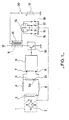
- the ignition device shown diagrammatically in FIG. 1 comprises a magnetic generator 1, of the kind such as that described, for example in the request FR-A-2 393 949.
- This generator consisting of a rotor 2 and an induced winding 3, delivers alternating signals V1, FIG. 3, the amplitude of which increases as the speed of rotation of the generator increases.
- alternating signals V1 are applied via resistors 4, 5, 6 to the inputs 7, 8 of a circuit 9 for controlling an electronic switch 10 controlling the passage of a current in the primary winding 11 of an ignition coil 12, so as to deliver a spark, of constant energy, to spark plugs 15, 16, 17, 18 connected consecutively to the secondary winding 13 of the ignition coil 12, by a distributor 14, in which is housed the magnetic generator 1, linked to a centrifugal advance mechanism, for obtaining an offset of the ignition point as a function of variations in the speed of rotation of the internal combustion engine, which drives the distributor 14.
- the ignition coil 12 is supplied by a battery 19, by means of an ignition key 20.
- the ignition point is triggered for a threshold S1 of the circuit 9 and for a positive value of the alternating signals V1, FIG. 3, delivered by the magnetic generator 1.
- a well-known drawback of magnetic generators is that the variation in their armature reaction, as a function of the speed of rotation, causes an increasing offset of the lighter point. mage in the direction of an ignition delay, delay represented by curve A in FIG. 2.
- This delay ⁇ is easily compensated by an adaptation of the characteristics of the centrifugal advance mechanism in the field of speeds, of rotation of the generator, greater than 400 revolutions / minute, which speed generally corresponds to the set point, PR, of ignition on motor vehicles.
- This adjustment point, PR represents the reference value of the ignition device, reference value in which the armature reaction of the generator is included, figure 2, curve B.
- the adaptation of the characteristics of the centrifugal advance mechanism consists in a modification of the force of the return springs of the masses deviating by the effect of the centrifugal force, and by a displacement of the stop limiting the movement of the said masses, this with respect to the same mechanism used, for example in a mechanical breaker ignition device.
- This offset in the direction of an advance a at ignition has the disadvantage that, during the starting phase of the internal combustion engine, it is not desirable that the force of the explosions, caused in advance with respect to at the top dead center of the cylinders, come to oppose the force produced by the electric motor starting the internal combustion engine.
- the resistors 4 and 6 have a value of 62,000 ohms, the resistance 5 has a value of 1,000 ohms and the capacitance of the capacitor 21 is 0.47 microfarad.
Landscapes
- Engineering & Computer Science (AREA)
- Chemical & Material Sciences (AREA)
- Combustion & Propulsion (AREA)
- Mechanical Engineering (AREA)
- General Engineering & Computer Science (AREA)
- Signal Processing (AREA)
- Physics & Mathematics (AREA)
- Electromagnetism (AREA)
- Ignition Installations For Internal Combustion Engines (AREA)
Claims (1)
- Elektronische Vorrichtung zum Verstellen des Zündzeitpunktes eines Verbrennungsmotors, insbesondere für Kraftfahrzeuge, mit einem von einem Rotor (2) und einer Ankerwicklung (3) . gebildeten magnetischen Generator (1), der Wechselspannungssignale erzeugt, welche über Widerstände (4, 5, 6) den Eingängen (7, 8) einer Steuerschaltung (9) eines elektronischen Unterbrechers (10) zugeführt werden, der das Fließen eines Stroms durch die Primärwicklung (11) einer Zündspule (12) steuert, um einen Zündfunken von konstanter Energie an Zündkerzen (15, 16, 17, 18) abzugeben, die von einem Verteiler (14) nacheinander mit der Sekundärwicklung (13) der Spule (12) verbunden werden, dadurch gekennzeichnet, daß zwischen das Ende (6a) des Widerstandes (6) und den Eingang (8) der Schaltung (9) ein Kondensator (21) so zwischengeschaltet ist, daß die Impedanzveränderung des Kondensators (21) die vom Generator (1) in seinem unteren Drehzahlbereich hervorgerufene Vorverstellung des Zündzeitpunktes ausgleicht.
Applications Claiming Priority (2)
| Application Number | Priority Date | Filing Date | Title |
|---|---|---|---|
| FR8217192 | 1982-10-14 | ||
| FR8217192A FR2534634B1 (fr) | 1982-10-14 | 1982-10-14 | Dispositif electronique de commande d'allumage d'un moteur a combustion interne, notamment pour vehicules automobiles |
Publications (2)
| Publication Number | Publication Date |
|---|---|
| EP0107560A1 EP0107560A1 (de) | 1984-05-02 |
| EP0107560B1 true EP0107560B1 (de) | 1986-09-10 |
Family
ID=9278260
Family Applications (1)
| Application Number | Title | Priority Date | Filing Date |
|---|---|---|---|
| EP83401955A Expired EP0107560B1 (de) | 1982-10-14 | 1983-10-07 | Elektronische Zündsteuervorrichtung für einen Kraftfahrzeugbrennkraftmotor |
Country Status (4)
| Country | Link |
|---|---|
| EP (1) | EP0107560B1 (de) |
| DE (1) | DE3366117D1 (de) |
| ES (1) | ES526244A0 (de) |
| FR (1) | FR2534634B1 (de) |
Families Citing this family (1)
| Publication number | Priority date | Publication date | Assignee | Title |
|---|---|---|---|---|
| DE3430660A1 (de) * | 1984-08-21 | 1986-03-06 | Robert Bosch Gmbh, 7000 Stuttgart | Zuendanlage fuer brennkraftmaschinen |
Family Cites Families (2)
| Publication number | Priority date | Publication date | Assignee | Title |
|---|---|---|---|---|
| GB1023928A (en) * | 1961-07-12 | 1966-03-30 | Lucas Industries Ltd | Spark ignition apparatus for internal combustion engines |
| JPS5037331B1 (de) * | 1969-10-22 | 1975-12-02 |
-
1982
- 1982-10-14 FR FR8217192A patent/FR2534634B1/fr not_active Expired
-
1983
- 1983-10-05 ES ES526244A patent/ES526244A0/es active Granted
- 1983-10-07 EP EP83401955A patent/EP0107560B1/de not_active Expired
- 1983-10-07 DE DE8383401955T patent/DE3366117D1/de not_active Expired
Also Published As
| Publication number | Publication date |
|---|---|
| EP0107560A1 (de) | 1984-05-02 |
| ES8405479A1 (es) | 1984-06-16 |
| FR2534634B1 (fr) | 1987-03-20 |
| FR2534634A1 (fr) | 1984-04-20 |
| ES526244A0 (es) | 1984-06-16 |
| DE3366117D1 (en) | 1986-10-16 |
Similar Documents
| Publication | Publication Date | Title |
|---|---|---|
| FR2510199A1 (fr) | Systeme d'allumage pour des moteurs a combustion interne | |
| JPH01216070A (ja) | 小型船舶の始動装置 | |
| EP0107560B1 (de) | Elektronische Zündsteuervorrichtung für einen Kraftfahrzeugbrennkraftmotor | |
| EP0202136A1 (de) | Verfahren und Anlage zur Drehzahlbegrenzung von Brennkraftmaschinen mit elektronischer Zündung | |
| EP0118646B1 (de) | Hilfszündanlage für Brennkraftmaschinen | |
| EP0102260B1 (de) | Verfahren und Anlage zur Regelung der verzögerten Zündung einer Brennkraftmaschine in der Startphase | |
| SE428142B (sv) | Tendanleggning for forbrenningsmotor med en magnetgenerator | |
| US6311664B1 (en) | Ignition coil output pulse controlled power switch for internal combustion engine | |
| US970794A (en) | Governing means for internal-combustion engines. | |
| JPH0351905B2 (de) | ||
| US4917060A (en) | Ignition device for starting an internal combustion engine | |
| EP0046092B1 (de) | Elektronische Vorrichtung zum Steuern der Zündung einer Brennkraftmaschine | |
| FR2753233A1 (fr) | Systeme de commande d'allumage pour un vehicule a embrayage centrifuge ou a transmission continue de type a courroie | |
| US3094108A (en) | Automatic spark advance device for ignition system | |
| US20050205073A1 (en) | Supplemental capacitive discharge ignition system | |
| EP0187071B1 (de) | Elektronische Schaltungsanordnung zur Verarbeitung eines Synchronsignals aus dem Zündzeitpunktsignal einer Brennkraftmaschine | |
| US803339A (en) | Internal-combustion-engine regulator. | |
| US1226083A (en) | Ignition device for internal-combustion engines. | |
| JPH0114423B2 (de) | ||
| US3099772A (en) | Auxiliary dynamotor for the ignition system of an internal combustion engine | |
| GB191302591A (en) | Device for Controlling the Speed of Motor Cars and the like Driven by Internal Combustion Engines. | |
| US1304835A (en) | Ignition system | |
| JPS58165576A (ja) | 車両の発進抑制装置 | |
| FR2493413A1 (fr) | Generateur de signaux agence pour declencher des processus d'allumage dans des moteurs a combustion interne | |
| US1883873A (en) | Ignition apparatus |
Legal Events
| Date | Code | Title | Description |
|---|---|---|---|
| PUAI | Public reference made under article 153(3) epc to a published international application that has entered the european phase |
Free format text: ORIGINAL CODE: 0009012 |
|
| AK | Designated contracting states |
Designated state(s): DE GB IT |
|
| 17P | Request for examination filed |
Effective date: 19840517 |
|
| GRAA | (expected) grant |
Free format text: ORIGINAL CODE: 0009210 |
|
| AK | Designated contracting states |
Kind code of ref document: B1 Designated state(s): DE GB IT |
|
| REF | Corresponds to: |
Ref document number: 3366117 Country of ref document: DE Date of ref document: 19861016 |
|
| ITF | It: translation for a ep patent filed | ||
| PLBE | No opposition filed within time limit |
Free format text: ORIGINAL CODE: 0009261 |
|
| STAA | Information on the status of an ep patent application or granted ep patent |
Free format text: STATUS: NO OPPOSITION FILED WITHIN TIME LIMIT |
|
| 26N | No opposition filed | ||
| PG25 | Lapsed in a contracting state [announced via postgrant information from national office to epo] |
Ref country code: GB Effective date: 19881007 |
|
| PG25 | Lapsed in a contracting state [announced via postgrant information from national office to epo] |
Ref country code: DE Effective date: 19890701 |
|
| GBPC | Gb: european patent ceased through non-payment of renewal fee |