EP0107572A1 - Vorrichtung und Verfahren zur Bestimmung des Kavitationsschutzes einer Verdränger pumpe - Google Patents
Vorrichtung und Verfahren zur Bestimmung des Kavitationsschutzes einer Verdränger pumpe Download PDFInfo
- Publication number
- EP0107572A1 EP0107572A1 EP83401984A EP83401984A EP0107572A1 EP 0107572 A1 EP0107572 A1 EP 0107572A1 EP 83401984 A EP83401984 A EP 83401984A EP 83401984 A EP83401984 A EP 83401984A EP 0107572 A1 EP0107572 A1 EP 0107572A1
- Authority
- EP
- European Patent Office
- Prior art keywords
- venturi
- positive displacement
- cavitation
- displacement pump
- pressure
- Prior art date
- Legal status (The legal status is an assumption and is not a legal conclusion. Google has not performed a legal analysis and makes no representation as to the accuracy of the status listed.)
- Granted
Links
- 238000006073 displacement reaction Methods 0.000 title claims abstract description 41
- 238000000034 method Methods 0.000 title claims description 4
- 238000001514 detection method Methods 0.000 title description 2
- 239000000446 fuel Substances 0.000 abstract description 9
- 239000012530 fluid Substances 0.000 description 4
- 238000009834 vaporization Methods 0.000 description 4
- 230000008016 vaporization Effects 0.000 description 3
- 238000005516 engineering process Methods 0.000 description 2
- 238000012544 monitoring process Methods 0.000 description 2
- 101100536354 Drosophila melanogaster tant gene Proteins 0.000 description 1
- 238000010276 construction Methods 0.000 description 1
- 238000007599 discharging Methods 0.000 description 1
- 238000011144 upstream manufacturing Methods 0.000 description 1
Images
Classifications
-
- F—MECHANICAL ENGINEERING; LIGHTING; HEATING; WEAPONS; BLASTING
- F04—POSITIVE - DISPLACEMENT MACHINES FOR LIQUIDS; PUMPS FOR LIQUIDS OR ELASTIC FLUIDS
- F04C—ROTARY-PISTON, OR OSCILLATING-PISTON, POSITIVE-DISPLACEMENT MACHINES FOR LIQUIDS; ROTARY-PISTON, OR OSCILLATING-PISTON, POSITIVE-DISPLACEMENT PUMPS
- F04C14/00—Control of, monitoring of, or safety arrangements for, machines, pumps or pumping installations
- F04C14/02—Control of, monitoring of, or safety arrangements for, machines, pumps or pumping installations specially adapted for several machines or pumps connected in series or in parallel
-
- F—MECHANICAL ENGINEERING; LIGHTING; HEATING; WEAPONS; BLASTING
- F02—COMBUSTION ENGINES; HOT-GAS OR COMBUSTION-PRODUCT ENGINE PLANTS
- F02C—GAS-TURBINE PLANTS; AIR INTAKES FOR JET-PROPULSION PLANTS; CONTROLLING FUEL SUPPLY IN AIR-BREATHING JET-PROPULSION PLANTS
- F02C7/00—Features, components parts, details or accessories, not provided for in, or of interest apart form groups F02C1/00 - F02C6/00; Air intakes for jet-propulsion plants
- F02C7/22—Fuel supply systems
- F02C7/236—Fuel delivery systems comprising two or more pumps
-
- F—MECHANICAL ENGINEERING; LIGHTING; HEATING; WEAPONS; BLASTING
- F04—POSITIVE - DISPLACEMENT MACHINES FOR LIQUIDS; PUMPS FOR LIQUIDS OR ELASTIC FLUIDS
- F04B—POSITIVE-DISPLACEMENT MACHINES FOR LIQUIDS; PUMPS
- F04B11/00—Equalisation of pulses, e.g. by use of air vessels; Counteracting cavitation
-
- F—MECHANICAL ENGINEERING; LIGHTING; HEATING; WEAPONS; BLASTING
- F04—POSITIVE - DISPLACEMENT MACHINES FOR LIQUIDS; PUMPS FOR LIQUIDS OR ELASTIC FLUIDS
- F04B—POSITIVE-DISPLACEMENT MACHINES FOR LIQUIDS; PUMPS
- F04B23/00—Pumping installations or systems
- F04B23/04—Combinations of two or more pumps
- F04B23/08—Combinations of two or more pumps the pumps being of different types
- F04B23/14—Combinations of two or more pumps the pumps being of different types at least one pump being of the non-positive-displacement type
-
- G—PHYSICS
- G05—CONTROLLING; REGULATING
- G05B—CONTROL OR REGULATING SYSTEMS IN GENERAL; FUNCTIONAL ELEMENTS OF SUCH SYSTEMS; MONITORING OR TESTING ARRANGEMENTS FOR SUCH SYSTEMS OR ELEMENTS
- G05B13/00—Adaptive control systems, i.e. systems automatically adjusting themselves to have a performance which is optimum according to some preassigned criterion
- G05B13/02—Adaptive control systems, i.e. systems automatically adjusting themselves to have a performance which is optimum according to some preassigned criterion electric
- G05B13/04—Adaptive control systems, i.e. systems automatically adjusting themselves to have a performance which is optimum according to some preassigned criterion electric involving the use of models or simulators
Definitions
- the invention relates to a device and a method for detecting the cavitation protection of a positive displacement pump.
- Positive displacement pumps in particular fuel pumps, are sensitive to the cavitation phenomenon which appears when the filling conditions are insufficient to avoid local or complete vaporization of the fuel in the suction area of the pump.
- This critical pressure Pc depends on the one hand on factors essentially related to the nature of the fuel at the temperature existing at the inlet of the pump and on the other hand, on a factor which, for a given technology pump, depends only on of the training regime.
- the object of the invention is to provide a signal representative of the difference between the booster pressure of a rotary positive displacement pump and the critical value of the pressure leading to cavitation.
- a device which comprises, on the pressure supply of the positive displacement pump, a bypass associating a flow generator proportional to the positive displacement of the positive displacement pump with a cavitation venturi discharging on a low pressure level, the characteristics of the flow generator and the venturi being predetermined as a function of the characteristics of the positive displacement pump so that the venturi reaches its cavitation regime before the cavitation of the positive displacement pump and that, at this regime, the pressure at the inlet of the convergent of the venturi is equal to the critical boost pressure of the positive displacement pump, the device further comprising means detecting the difference between the supply pressure of the positive displacement pump and the inlet pressure of the venturi.
- the flow generator is a volumetric machine driven in proportion to the drive of the volumetric pump.
- the positive displacement pump is supplied by a booster pump and the venturi delivers on the output of the inductor of said booster pump.
- the venturi has an adjustable section neck, which makes it possible to regulate the cavitation regime of the pump.
- the invention also relates to a method for detecting the cavitation protection of a positive displacement pump, consisting in deriving from the supply of the positive displacement pump a flow rate proportional to the flow rate of said pump on a flow cavitation venturi. on a low pressure level. by adjusting said proportional flow and the cavitation of the venturi so that it reaches its cavitation regime before the cavitation of the positive displacement pump at quo, At this regime, the propossion to the cone of the convergent of the venturi is equal to the pressure of critical boost of the positive displacement pump, and that the difference is detected between the supply pressure of the positive displacement pump and the inlet pressure of the venturi.
- the invention differs from anti-cavitation devices known for example from the documents FR - A 2 268 956 and FR - 2 343 138 in that it above all proposes a system for monitoring cavitation.
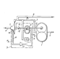
- the positive displacement pump 1 to be monitored is supplied through a line 2 by a booster pump 3 itself connected by line 4 to a power source not shown.
- the pump 1 delivers a fluid under high pressure in the delivery pipe 5, while a valve return is provided on the pipe 2 through the return pipe 6.
- the device of the invention 7 the assembly of which is schematically circumscribed by the dashed line, comprises a bypass line 8-9-10 connected to the supply line 2 of the positive displacement pump 1.
- a flow generator 11 in the form of a volumetric machine (such as gear pump, piston, vane, ...) whose flow is proportional to the pump flow volumetric 1 which is shown diagrammatically by a common drive shaft 12 for the booster pump 3, the volumetric machine 11 and the pump 1.
- a volumetric machine such as gear pump, piston, vane, .
- the volumetric machine 11 has lower linear (or tangential) speeds than those of the pump to be monitored 1 so as to operate outside the cavitation regime when the critical boost pressure is reached or about to be reached in the pump to monitor.
- the volumetric machine 11 delivers on a cavitation venturi 13, itself delivering on a pressure level P 3 very low compared to the pressure P 1 supplying the pump 1, for example on the outlet 14 of the inductor of the booster pump 3.
- a differential pressure detector 15 detects the pressure difference between the supply pressure P 1 of the pump 1 and the pressure P 2 at the inlet of the convergent of the venturi 13, in the pipe section 9.
- K 1 is a proportionality factor depending on the characteristics of the volumetric machine 11 (its displacement)
- K 2 a proportionality factor depending on the characteristics of the venturi 13 (its neck section).
- the pressure P 2 is smaller than P 1 , and the cavitation of the pump to be monitored is not to be feared.
- the detected cavitation regime can be made variable by using a venturi with a neck section adjustable by a needle.
- the monitoring of the pressure difference P 1 - P 2 given by the detector 15 makes it possible to know the operating margin outside cavitation, this detection being able to be used as an alarm, (allowing for example on a supersonic aircraft to switch the fuel supply coming from a warmer tank, to a tank where the fuel is still relatively cold), or as a regulation parameter making it possible to restore a sufficient booster pressure.
Landscapes
- Engineering & Computer Science (AREA)
- Mechanical Engineering (AREA)
- General Engineering & Computer Science (AREA)
- Combustion & Propulsion (AREA)
- Chemical & Material Sciences (AREA)
- Evolutionary Computation (AREA)
- Software Systems (AREA)
- Physics & Mathematics (AREA)
- General Physics & Mathematics (AREA)
- Automation & Control Theory (AREA)
- Medical Informatics (AREA)
- Health & Medical Sciences (AREA)
- Computer Vision & Pattern Recognition (AREA)
- Artificial Intelligence (AREA)
- Structures Of Non-Positive Displacement Pumps (AREA)
- Reciprocating Pumps (AREA)
- Jet Pumps And Other Pumps (AREA)
Applications Claiming Priority (2)
| Application Number | Priority Date | Filing Date | Title |
|---|---|---|---|
| FR8218053A FR2535408A1 (fr) | 1982-10-28 | 1982-10-28 | Dispositif et procede de detection de la garde a la cavitation d'une pompe volumetrique |
| FR8218053 | 1982-10-28 |
Publications (2)
| Publication Number | Publication Date |
|---|---|
| EP0107572A1 true EP0107572A1 (de) | 1984-05-02 |
| EP0107572B1 EP0107572B1 (de) | 1986-09-10 |
Family
ID=9278680
Family Applications (1)
| Application Number | Title | Priority Date | Filing Date |
|---|---|---|---|
| EP83401984A Expired EP0107572B1 (de) | 1982-10-28 | 1983-10-12 | Vorrichtung und Verfahren zur Bestimmung des Kavitationsschutzes einer Verdränger pumpe |
Country Status (5)
| Country | Link |
|---|---|
| US (1) | US4512722A (de) |
| EP (1) | EP0107572B1 (de) |
| JP (1) | JPS5999075A (de) |
| DE (1) | DE3366118D1 (de) |
| FR (1) | FR2535408A1 (de) |
Cited By (2)
| Publication number | Priority date | Publication date | Assignee | Title |
|---|---|---|---|---|
| EP0194474A3 (en) * | 1985-03-14 | 1989-03-08 | Klaus Metzger | Method for regulating cavitation |
| WO2018115653A1 (fr) * | 2016-12-22 | 2018-06-28 | Safran Aircraft Engines | Procede ameliore de regulation d'un circuit d'alimentation |
Families Citing this family (18)
| Publication number | Priority date | Publication date | Assignee | Title |
|---|---|---|---|---|
| US4746276A (en) * | 1987-02-27 | 1988-05-24 | Dana Corporation | Gear pump having conditional dry valve closure structure |
| DE3725754A1 (de) * | 1987-08-04 | 1989-02-16 | Busch Dieter & Co Prueftech | Einrichtung zum ueberwachen von pumpen auf gefaehrdung durch kavitation |
| US6537817B1 (en) | 1993-05-31 | 2003-03-25 | Packard Instrument Company | Piezoelectric-drop-on-demand technology |
| US6203759B1 (en) | 1996-05-31 | 2001-03-20 | Packard Instrument Company | Microvolume liquid handling system |
| US6521187B1 (en) | 1996-05-31 | 2003-02-18 | Packard Instrument Company | Dispensing liquid drops onto porous brittle substrates |
| US5601414A (en) * | 1995-09-25 | 1997-02-11 | Imo Industries, Inc. | Interstage liquid/gas phase detector |
| US5772403A (en) * | 1996-03-27 | 1998-06-30 | Butterworth Jetting Systems, Inc. | Programmable pump monitoring and shutdown system |
| US6083762A (en) * | 1996-05-31 | 2000-07-04 | Packard Instruments Company | Microvolume liquid handling system |
| US6663349B1 (en) | 2001-03-02 | 2003-12-16 | Reliance Electric Technologies, Llc | System and method for controlling pump cavitation and blockage |
| US6655922B1 (en) * | 2001-08-10 | 2003-12-02 | Rockwell Automation Technologies, Inc. | System and method for detecting and diagnosing pump cavitation |
| US7093437B2 (en) * | 2004-01-29 | 2006-08-22 | United Technologies Corporation | Extended operability aircraft fuel delivery system |
| GB0525573D0 (en) * | 2005-12-16 | 2006-01-25 | Rolls Royce Plc | Engine Health Monitoring |
| US9546652B2 (en) * | 2012-03-28 | 2017-01-17 | Imo Industries, Inc. | System and method for monitoring and control of cavitation in positive displacement pumps |
| JP5999739B2 (ja) * | 2012-03-28 | 2016-09-28 | アイエムオー・インダストリーズ・インコーポレーテッド | 容積式ポンプにおけるキャビテーションの監視および制御のためのシステムおよび方法 |
| US10422332B2 (en) | 2013-03-11 | 2019-09-24 | Circor Pumps North America, Llc | Intelligent pump monitoring and control system |
| US9776728B2 (en) | 2014-07-22 | 2017-10-03 | Hamilton Sundstrand Corporation | Dual-stage gear pump with reduced pressure ripple |
| FR3090042B1 (fr) * | 2018-12-17 | 2021-04-09 | Safran Aircraft Engines | Dispositif amélioré de régulation de débit d’alimentation |
| IT202300027930A1 (it) * | 2023-12-22 | 2025-06-22 | Cnh Ind Italia Spa | Sistema idraulico migliorato per un veicolo da lavoro e relativo veicolo da lavoro |
Citations (5)
| Publication number | Priority date | Publication date | Assignee | Title |
|---|---|---|---|---|
| FR1282772A (fr) * | 1961-01-16 | 1962-01-27 | Lucas Industries Ltd | Perfectionnement aux installations d'alimentation en combustible des avions |
| FR2170637A5 (de) * | 1972-01-06 | 1973-09-14 | Plessey Handel Investment Ag | |
| US3942724A (en) * | 1974-08-01 | 1976-03-09 | S.R.C. Laboratories, Inc. | Variable throat nozzle |
| US3963378A (en) * | 1975-06-04 | 1976-06-15 | Caterpillar Tractor Co. | Part throttle control -- pump override |
| FR2320435A1 (fr) * | 1975-08-06 | 1977-03-04 | Sundstrand Corp | Circuit de distribution de fluide |
Family Cites Families (6)
| Publication number | Priority date | Publication date | Assignee | Title |
|---|---|---|---|---|
| US2640423A (en) * | 1950-01-18 | 1953-06-02 | Gen Motors Corp | Fuel system |
| US2782595A (en) * | 1952-08-29 | 1957-02-26 | Westinghouse Electric Corp | Fuel system for a gas turbine engine |
| FR2268956B1 (de) * | 1974-04-24 | 1977-06-24 | Messier Hispano Sa | |
| US3987628A (en) * | 1976-03-04 | 1976-10-26 | Deere & Company | Charge pump augmenting device |
| US4311436A (en) * | 1979-11-13 | 1982-01-19 | International Business Machines Corporation | Fluid pressure and velocity sensing apparatus |
| US4404812A (en) * | 1981-11-27 | 1983-09-20 | Carrier Corporation | Method and apparatus for controlling the operation of a centrifugal compressor in a refrigeration system |
-
1982
- 1982-10-28 FR FR8218053A patent/FR2535408A1/fr active Granted
-
1983
- 1983-10-12 EP EP83401984A patent/EP0107572B1/de not_active Expired
- 1983-10-12 DE DE8383401984T patent/DE3366118D1/de not_active Expired
- 1983-10-18 US US06/543,067 patent/US4512722A/en not_active Expired - Lifetime
- 1983-10-25 JP JP58199879A patent/JPS5999075A/ja active Granted
Patent Citations (5)
| Publication number | Priority date | Publication date | Assignee | Title |
|---|---|---|---|---|
| FR1282772A (fr) * | 1961-01-16 | 1962-01-27 | Lucas Industries Ltd | Perfectionnement aux installations d'alimentation en combustible des avions |
| FR2170637A5 (de) * | 1972-01-06 | 1973-09-14 | Plessey Handel Investment Ag | |
| US3942724A (en) * | 1974-08-01 | 1976-03-09 | S.R.C. Laboratories, Inc. | Variable throat nozzle |
| US3963378A (en) * | 1975-06-04 | 1976-06-15 | Caterpillar Tractor Co. | Part throttle control -- pump override |
| FR2320435A1 (fr) * | 1975-08-06 | 1977-03-04 | Sundstrand Corp | Circuit de distribution de fluide |
Non-Patent Citations (2)
| Title |
|---|
| IBM TECHNICAL DISCLOSURE BULLETIN, vol. 11, no. 9, février 1969, New York (US) * |
| MESURES, REGULATION, AUTOMATISME, vol. 34, no. 10, octobre 1969, Paris (FR) * |
Cited By (5)
| Publication number | Priority date | Publication date | Assignee | Title |
|---|---|---|---|---|
| EP0194474A3 (en) * | 1985-03-14 | 1989-03-08 | Klaus Metzger | Method for regulating cavitation |
| WO2018115653A1 (fr) * | 2016-12-22 | 2018-06-28 | Safran Aircraft Engines | Procede ameliore de regulation d'un circuit d'alimentation |
| FR3061240A1 (fr) * | 2016-12-22 | 2018-06-29 | Safran Aircraft Engines | Procede ameliore de regulation d'un circuit d'alimentation |
| CN110177927A (zh) * | 2016-12-22 | 2019-08-27 | 赛峰航空器发动机 | 用于调节供给回路的改良方法 |
| US11306662B2 (en) | 2016-12-22 | 2022-04-19 | Safran Aircraft Engines | Method for regulating a supply circuit |
Also Published As
| Publication number | Publication date |
|---|---|
| JPS5999075A (ja) | 1984-06-07 |
| DE3366118D1 (en) | 1986-10-16 |
| FR2535408A1 (fr) | 1984-05-04 |
| US4512722A (en) | 1985-04-23 |
| EP0107572B1 (de) | 1986-09-10 |
| JPH048633B2 (de) | 1992-02-17 |
| FR2535408B1 (de) | 1984-12-21 |
Similar Documents
| Publication | Publication Date | Title |
|---|---|---|
| EP0107572B1 (de) | Vorrichtung und Verfahren zur Bestimmung des Kavitationsschutzes einer Verdränger pumpe | |
| EP2564045B1 (de) | Kraftstoffsystem einer turbomaschine | |
| EP1685025B1 (de) | Fluidkühlsystem für flugzeuge und flugzeug ausgestattet mit einem solchen system | |
| US4706636A (en) | Purge and prime fuel delivery system and method | |
| EP3137756B1 (de) | Flüssigkeitsversorgungskreislauf mit variablen geometrien für eine turbomaschine ohne volumetrische pumpe | |
| FR2953563A1 (fr) | Installation d'alimentation en carburant d'un turboreacteur d'avion | |
| EP0346462A1 (de) | Brennstoffzufuhrsystem mit von einer turbine angetriebenen pumpe | |
| EP0533567B1 (de) | Schutzsystem gegen die Löschung einer Turbomaschine bei Eindrigen von Wasser oder Hagel | |
| EP0473494B1 (de) | Brennstoffversorgungssystem für einen Turbomotor | |
| EP3938638B1 (de) | Verfahren zur regelung der temperatur der abgase einer turbomaschine | |
| FR3081193A1 (fr) | Compresseur et procede de controle du debit | |
| EP3670867B1 (de) | Verbesserte vorrichtung zur regulierung des versorgungsdurchsatzes | |
| FR2859761A1 (fr) | Moteur a turbine d'helicoptere | |
| FR3020403B1 (fr) | Circuit d'alimentation en fluide de geometries variables sans pompe volumetrique et circuit d'alimentation de chambre de combustion avec pompe volumetrique electrique | |
| FR2704905A1 (fr) | Turbomachine comportant un régulateur secondaire du débit de son alimentation en carburant. | |
| FR3153376A1 (fr) | Systeme d’alimentation en carburant d’une turbomachine | |
| FR3153856A1 (fr) | Systeme d’alimentation en carburant de turbomachine | |
| EP0049200A1 (de) | Antriebsvorrichtung für die Klappen der Düse eines Gasturbinentriebwerks | |
| FR3153857A1 (fr) | Systeme d’alimentation en carburant de turbomachine | |
| FR3016185A1 (fr) | Moteur a combustion de vehicule automobile a systeme de degazage securise | |
| FR3020404A1 (fr) | Circuit d'alimentation en fluide de geometries variables de turbomachine sans pompe volumetrique | |
| WO2024252096A1 (fr) | Dispositif de détection de carburant dans l'huile par analyse de phase gazeuse | |
| WO2026003451A1 (fr) | Turbomachine comprenant un circuit auxiliaire d'alimentation en huile | |
| FR3050778A1 (fr) | Pompe a jet pour turbomachine, comprenant un aubage pour mise en rotation de fluide actif | |
| FR3020405A1 (fr) | Systeme d'alimentation a plusieurs pompes centrifuges en amont d'une pompe volumetrique |
Legal Events
| Date | Code | Title | Description |
|---|---|---|---|
| PUAI | Public reference made under article 153(3) epc to a published international application that has entered the european phase |
Free format text: ORIGINAL CODE: 0009012 |
|
| 17P | Request for examination filed |
Effective date: 19831020 |
|
| AK | Designated contracting states |
Designated state(s): DE FR GB |
|
| GRAA | (expected) grant |
Free format text: ORIGINAL CODE: 0009210 |
|
| AK | Designated contracting states |
Kind code of ref document: B1 Designated state(s): DE FR GB |
|
| REF | Corresponds to: |
Ref document number: 3366118 Country of ref document: DE Date of ref document: 19861016 |
|
| PLBE | No opposition filed within time limit |
Free format text: ORIGINAL CODE: 0009261 |
|
| STAA | Information on the status of an ep patent application or granted ep patent |
Free format text: STATUS: NO OPPOSITION FILED WITHIN TIME LIMIT |
|
| 26N | No opposition filed | ||
| PGFP | Annual fee paid to national office [announced via postgrant information from national office to epo] |
Ref country code: DE Payment date: 19951229 Year of fee payment: 13 |
|
| PGFP | Annual fee paid to national office [announced via postgrant information from national office to epo] |
Ref country code: FR Payment date: 19960912 Year of fee payment: 14 |
|
| PGFP | Annual fee paid to national office [announced via postgrant information from national office to epo] |
Ref country code: GB Payment date: 19961003 Year of fee payment: 14 |
|
| PG25 | Lapsed in a contracting state [announced via postgrant information from national office to epo] |
Ref country code: DE Effective date: 19970701 |
|
| PG25 | Lapsed in a contracting state [announced via postgrant information from national office to epo] |
Ref country code: GB Free format text: LAPSE BECAUSE OF NON-PAYMENT OF DUE FEES Effective date: 19971012 |
|
| PG25 | Lapsed in a contracting state [announced via postgrant information from national office to epo] |
Ref country code: FR Free format text: THE PATENT HAS BEEN ANNULLED BY A DECISION OF A NATIONAL AUTHORITY Effective date: 19971031 |
|
| GBPC | Gb: european patent ceased through non-payment of renewal fee |
Effective date: 19971012 |
|
| REG | Reference to a national code |
Ref country code: FR Ref legal event code: ST |