EP0107580A2 - Dispositif pour la détection et la quantification d'agglutinats - Google Patents
Dispositif pour la détection et la quantification d'agglutinats Download PDFInfo
- Publication number
- EP0107580A2 EP0107580A2 EP83402000A EP83402000A EP0107580A2 EP 0107580 A2 EP0107580 A2 EP 0107580A2 EP 83402000 A EP83402000 A EP 83402000A EP 83402000 A EP83402000 A EP 83402000A EP 0107580 A2 EP0107580 A2 EP 0107580A2
- Authority
- EP
- European Patent Office
- Prior art keywords
- disc
- axis
- containers
- photosensitive elements
- cells
- Prior art date
- Legal status (The legal status is an assumption and is not a legal conclusion. Google has not performed a legal analysis and makes no representation as to the accuracy of the status listed.)
- Granted
Links
Images


Classifications
-
- G—PHYSICS
- G01—MEASURING; TESTING
- G01N—INVESTIGATING OR ANALYSING MATERIALS BY DETERMINING THEIR CHEMICAL OR PHYSICAL PROPERTIES
- G01N33/00—Investigating or analysing materials by specific methods not covered by groups G01N1/00 - G01N31/00
- G01N33/48—Biological material, e.g. blood, urine; Haemocytometers
- G01N33/50—Chemical analysis of biological material, e.g. blood, urine; Testing involving biospecific ligand binding methods; Immunological testing
- G01N33/80—Chemical analysis of biological material, e.g. blood, urine; Testing involving biospecific ligand binding methods; Immunological testing involving blood groups or blood types or red blood cells
-
- G—PHYSICS
- G01—MEASURING; TESTING
- G01N—INVESTIGATING OR ANALYSING MATERIALS BY DETERMINING THEIR CHEMICAL OR PHYSICAL PROPERTIES
- G01N21/00—Investigating or analysing materials by the use of optical means, i.e. using sub-millimetre waves, infrared, visible or ultraviolet light
- G01N21/17—Systems in which incident light is modified in accordance with the properties of the material investigated
- G01N21/25—Colour; Spectral properties, i.e. comparison of effect of material on the light at two or more different wavelengths or wavelength bands
- G01N21/251—Colorimeters; Construction thereof
- G01N21/253—Colorimeters; Construction thereof for batch operation, i.e. multisample apparatus
-
- G—PHYSICS
- G01—MEASURING; TESTING
- G01N—INVESTIGATING OR ANALYSING MATERIALS BY DETERMINING THEIR CHEMICAL OR PHYSICAL PROPERTIES
- G01N21/00—Investigating or analysing materials by the use of optical means, i.e. using sub-millimetre waves, infrared, visible or ultraviolet light
- G01N21/75—Systems in which material is subjected to a chemical reaction, the progress or the result of the reaction being investigated
- G01N21/77—Systems in which material is subjected to a chemical reaction, the progress or the result of the reaction being investigated by observing the effect on a chemical indicator
- G01N21/82—Systems in which material is subjected to a chemical reaction, the progress or the result of the reaction being investigated by observing the effect on a chemical indicator producing a precipitate or turbidity
-
- G—PHYSICS
- G01—MEASURING; TESTING
- G01N—INVESTIGATING OR ANALYSING MATERIALS BY DETERMINING THEIR CHEMICAL OR PHYSICAL PROPERTIES
- G01N21/00—Investigating or analysing materials by the use of optical means, i.e. using sub-millimetre waves, infrared, visible or ultraviolet light
- G01N21/17—Systems in which incident light is modified in accordance with the properties of the material investigated
- G01N21/59—Transmissivity
- G01N21/5907—Densitometers
- G01N2021/5957—Densitometers using an image detector type detector, e.g. CCD
-
- Y—GENERAL TAGGING OF NEW TECHNOLOGICAL DEVELOPMENTS; GENERAL TAGGING OF CROSS-SECTIONAL TECHNOLOGIES SPANNING OVER SEVERAL SECTIONS OF THE IPC; TECHNICAL SUBJECTS COVERED BY FORMER USPC CROSS-REFERENCE ART COLLECTIONS [XRACs] AND DIGESTS
- Y10—TECHNICAL SUBJECTS COVERED BY FORMER USPC
- Y10S—TECHNICAL SUBJECTS COVERED BY FORMER USPC CROSS-REFERENCE ART COLLECTIONS [XRACs] AND DIGESTS
- Y10S436/00—Chemistry: analytical and immunological testing
- Y10S436/805—Optical property
-
- Y—GENERAL TAGGING OF NEW TECHNOLOGICAL DEVELOPMENTS; GENERAL TAGGING OF CROSS-SECTIONAL TECHNOLOGIES SPANNING OVER SEVERAL SECTIONS OF THE IPC; TECHNICAL SUBJECTS COVERED BY FORMER USPC CROSS-REFERENCE ART COLLECTIONS [XRACs] AND DIGESTS
- Y10—TECHNICAL SUBJECTS COVERED BY FORMER USPC
- Y10T—TECHNICAL SUBJECTS COVERED BY FORMER US CLASSIFICATION
- Y10T436/00—Chemistry: analytical and immunological testing
- Y10T436/11—Automated chemical analysis
- Y10T436/111666—Utilizing a centrifuge or compartmented rotor
Definitions
- the present invention relates to a device for the detection and quantification of agglutinates capable of being formed, under the action of at least one reagent, by particles in suspension in a liquid.
- the device for the detection and quantification in containers of which at least the bottoms are transparent, of agglutinates capable of being formed, under the action of at least one liquid reagent, by particles in suspension in doses of liquids to be tested located in said containers, device comprising a linear arrangement of a plurality n of photosensitive elements observing by transparency the bottoms of said containers containing any agglutinates by scanning said bottoms of said containers, so as to form nxm observation points distributed along a rectangular or square surface occupying most of the bottom surface of each container, said containers being made up of cells distributed along radii of a transparent horizontal disc able to rotate around its vertical axis, is remarkable in that an oscillating arm rotating around a vertical axis and provided with means for collecting and delivering liquid doses is provided for collecting such doses in reagent and liquids to be tested and bring them into said cells of the rotating disc, in that said linear arrangement of photosensitive elements is disposed at a fixed post orthogonally to a
- the oscillating arm can introduce into each cell of the rotating disc a liquid to be tested and the corresponding reagent. After reaction, each cell is examined by the arrangement of photosensitive elements during the translation of the axis of the disc, translation of which the amplitude is sufficient for all the cells of a radius of the disc to be observed, each in I'm not.
- the swinging arm carries as many removal and restitution means as a disk spoke has cells so that the swinging arm loads all the cells with a spoke at one time.
- the linear arrangement of photosensitive elements is arranged orthogonally to the vertical plane passing through the vertical axes of the transparent disc and of the swinging arm, on the side of the axis of the disc opposite to said swinging arm, so that the disk must rotate 180 'so that a radius of cells loaded with doses of liquids to be tested and of reagent can be read by said arrangement.
- the reagent tanks are arranged at a fixed position on one side of the vertical plane defined by the vertical axes of the swinging arm and of the disc, while the liquid tanks to be tested are associated with means of transport not advancing them. not parallel to this vertical plane, but on the side opposite to said reagent reservoirs.
- the arrangement of photosensitive elements can be of the type of charge coupled diode array, generally designated by the letters CCD, DTC or CCPD.
- CCD charge coupled diode array
- DTC charge coupled diode array
- CCPD charge coupled diode array
- the rectilinear bar has 256 CCD photodiodes, each having a resolution of 25 ⁇ m, the video information is digitized into 256 levels of gray, and the analyzed image is a square centered on said transparent base and formed by 256 scans separated by 25 microns.
- the installation for the recognition of blood groups comprises a device 1 according to the invention for the detection and quantification of agglutinates, associated with a display device 2, with a control device 3 and with a printing device 4.
- the entire installation is controlled by a microprocessor (not shown) according to a process not described below.
- the device 1 comprises a horizontal oscillating arm 5 capable of rotating around a vertical axis 6.
- the arm 5 carries a plurality of vertical syringes 7, the pistons of which can be actuated to suck or discharge a liquid.
- the syringes 7 scan an annular zone 8.
- reagent containers 9 in each of which the vertical syringes 7 can take a reagent and a rinsing container 10.
- the device 1 comprises a vertical axis 11 capable of rotating a disk 12 of transparent material in which the cells 13 are formed.
- the disk 12 comprises an upper disk 14 and a lower disc 15 superimposed and assembled for example by gluing.
- the discs 14 and 15 are made of a transparent synthetic material and are provided in their center with holes 16 to allow the passage of the rotary drive shaft 11 when the discs 1 and 2 are superimposed and secured.
- the upper disc 14 is provided with a plurality of through holes 17, the axes 22 of which are orthogonal to the plane of the disc 14 are distributed at a plurality of points 18 located at the intersection of spokes 19 and concentric circles 20. Furthermore, each hole 17 is flared upwards.
- the lower transparent disc 15 has a plurality of blind holes 21 whose axes 23 are distributed at a plurality of points located at the intersection of spokes and concentric circles and are offset with respect to the axes 22.
- the blind holes 21 are, in the lower disc 15, extended in the direction of the holes 17, by a communication hole 24 with a flat bottom, sufficiently elongated so that the upper edge of the funnels 17 is outside the container 21, or at least emerges from the bottom of the latter a field of vision 25 covering practically most of said bottom.
- the annular zone 8 for scanning the syringes 7 cuts the disc 12 so that it is possible to fill all the cells 13 (or container 13) arranged on a radius 19 of the disc 12, in doses of reagents coming from the reservoirs 9 by introducing the syringe needles 7 in the corresponding funnels 17, the liquid then passing through the holes 17 and 24 to reach the blind hole 21.
- agitation or centrifugation is required To do this, it suffices to subject the disc 12 to this movement and, since the holes 21 are closed by the disc 14, there is no risk of the liquid contained in the containers 13 escaping towards the outside.
- the reservoirs 26 consist (see FIG. 5) of transparent blocks 27 removably carrying tubes 28 which contain blood samples from donors and in which recesses 29 possibly containing dilutions of the liquids of said tubes are made.
- the reservoirs 26 are introduced into the device 1 by a conveyor 30 which passes them successively to different treatment stations 31, 32 and 33, before bringing them to station 34 where the syringes 7 of the arm 5 can withdraw the liquid which they -contain.
- each cell 13 of the disc 12 can serve as a reaction vessel between a liquid coming from a tank 26 and a reagent coming from a tank 9.
- the device 1 comprises a strip 35 of CCD diodes, placed under the disc 12 opposite a lighting device 36.
- the strip 35 and the lighting device 36 are opposite the arm 5 with respect to the axis 11 and the bar 35 is orthogonal to the vertical plane defined by the axes 6 and 11.
- the bar 35 examines by transparency the bottom 25 of each cell 13 according to m observations each shifted by one step. So that all the cells 13 with a radius 19 of the disc 12 can each be examined in m steps, the axis 11 of the said disc is made movable in horizontal translation, orthogonally to the said bar 35.
- Figures 6 and 7 show that the axis 11 of the disc 12 is integral with a carriage 37 movable relative to the base plate 38 of the device.
- This carriage 37 includes a frame 39 carrying a motor 40 and a plain bearing 41 for the axis 11.
- the output shaft of the motor 40 rotates a pulley 42 which is connected to a pulley 43 fixed on the axis 11, by means of a toothed belt 44.
- the carriage 37 is guided in translation by a rail 45 and it moves under the action of a jack 46, the rod 47 of which is connected to the carriage 37 by a rod 48.
- the axis 11 can slide in a slot 49, of the base plate 38, parallel to the rail 45 and orthogonal to the strip 35 of CCD diodes.
- the carriage 37 can also carry a vibrator 49 intended to animate sporadically, against the action of a spring 50, the axis 11 of an alternating movement parallel to its axis, in order to possibly agitate the liquid contained in the cells 13 of the disc 12.
- the disc 12 is advanced by the cylinder 46 in the direction of arrow F 1 so that the arrangement 35 is perpendicular to the external limit 51 of the field 25 of the bottom of the first cell 13 1. Then, step by step, the cylinder is moved m times so that the n photosensitive elements of the arrangement 35 examines in nxm points the said fields 25.
- the jack 46 moves the axis 11, still in the direction F1, so that the outer limit 52 of field 25 of the bottom of the second cell 13 2 arrives at the base of the photosensitive elements of arrangement 35.
- This second cell 13 2 is read identically and the process continues until the complete reading of cell 13p.
- the cylinder 46 returns the axis 11 to its initial position (arrow F 2 ).
Landscapes
- Health & Medical Sciences (AREA)
- Life Sciences & Earth Sciences (AREA)
- Chemical & Material Sciences (AREA)
- Physics & Mathematics (AREA)
- Engineering & Computer Science (AREA)
- Immunology (AREA)
- Hematology (AREA)
- Biochemistry (AREA)
- General Health & Medical Sciences (AREA)
- General Physics & Mathematics (AREA)
- Pathology (AREA)
- Analytical Chemistry (AREA)
- Biomedical Technology (AREA)
- Urology & Nephrology (AREA)
- Molecular Biology (AREA)
- Cell Biology (AREA)
- Biotechnology (AREA)
- Chemical Kinetics & Catalysis (AREA)
- Microbiology (AREA)
- Spectroscopy & Molecular Physics (AREA)
- Plasma & Fusion (AREA)
- Food Science & Technology (AREA)
- Medicinal Chemistry (AREA)
- Investigating Or Analysing Biological Materials (AREA)
- Automatic Analysis And Handling Materials Therefor (AREA)
- Optical Measuring Cells (AREA)
- Investigating Or Analysing Materials By Optical Means (AREA)
- Analysing Materials By The Use Of Radiation (AREA)
Abstract
Description
- La présente invention concerne un dispositif pour la détection et la quantification d'agglutinats susceptibles d'être formés, sous l'action d'au moins un réactif, par des particules en suspension dans un liquide.
- Elle peut être utilisée chaque fois que l'on a à détecter et à quantifier des agglutinats. Cependant, elle s'applique particulièrement bien en immunohématologie, notamment en vue de la détermination des groupes sanguins. On sait en effet que la détermination des groupes sanguins est liée à la recherche de l'existence dans le sang d'antigènes érythrocytaires. Les réactions immuno- cytologiques, face à un antigène de groupe spécifique, se traduisent par un phénomène d'agglutination des hématies, si ces dernières appartiennent à un autre groupe. Ces hématies peuvent former soit des agglutinats unifor- sans hématies libres, soit quelques gros agglutinats, ou bien encore un grand nombre de petits agglutinats.
- Quoique la présente invention ne soit pas limitée dans ses applications à l'immunohématologie, elle sera décrite ci-après plus particulièrement en rapport avec cette application particulière.
- Selon l'invention, le dispositif pour la détection et la quantification, dans des récipients dont au moins les fonds sont transparents, d'agglutinats susceptibles d'être formés, sous l'action d'au moins un réactif liquide, par des particules en suspension dans des doses de liquides à tester se trouvant dans lesdits récipients, dispositif comportant un agencement linéaire d'une pluralité n d'éléments photosensibles observant par transparence les fonds desdits récipients contenant les éventuels agglutinats en balayant lesdits fonds desdits récipients, de façon à former n x m points d'observation répartis selon une surface rectangulaire ou carrée occupant la plus grande partie de la surface du fond de chaque récipient, lesdits récipients étant constitués d'alvéoles répartis selon des rayons d'un disque horizontal transparent pouvant tourner autour de son axe vertical, est remarquable en ce qu'un bras oscillant tournant autour d'un axe vertical et pourvu de moyens de prélèvement et de restitution de doses liquides est prévu pour prélever de telles doses dans des réservoirs à réactifs et à liquides à tester et les amener dans lesdits alvéoles du disque tournant, en ce que ledit agencement linéaire d'éléments photosensibles est disposé à poste fixe orthogonalement à un diamètre du disque transparent et en ce que l'axe de rotation du disque est monté mobile en translation orthogonalement audit agencement linéaire d'éléments photosensibles.
- Ainsi, par l'intermédiaire de ses moyens de prélèvement et de restitution de doses liquides, qui peuvent par exemple être des seringues, le bras oscillant peut introduire dans chaque alvéole du disque tournant un liquide à tester et le réactif correspondant. Après réaction, chaque alvéole est examiné par l'agencement d'éléments photosensibles au cours de la translation de l'axe du disque, translation dont l'amplitude est suffisante pour que tous les alvéoles d'un rayon du disque soit observé, chacun en m pas.
- Avantageusement, le bras oscillant porte autant de moyens de prélèvement et de restitution qu'un rayon de disque comporte d'alvéoles de sorte que le bras oscillant charge tous les alvéoles d'un rayon en une seule fois.
- Dans un mode avantageux de réalisation, l'agencement linéaire d'éléments photosensibles est disposé orthogonalement au plan vertical passant par les axes verticaux du disque transparent et du bras oscillant, du côté de l'axe du disque opposé audit bras oscillant, de sorte que le disque doit effectuer une rotation de 180' pour qu'un rayon d'alvéoles chargés en doses de liquides à tester et en réactif puisse être lu par ledit agencement.
- De préférence, les réservoirs à réactifs sont disposés à poste fixe d'un côté du plan vertical défini par les axes verticaux de bras oscillant et du disque, tandis que les réservoirs à liquides à tester sont associés à des moyens de transport les avançant pas à pas, parallèlement à ce plan vertical, mais du côté opposé auxdits réservoirs de réactifs.
- L'agencement d'éléments photosensibles peut être du type barrette de diodes à couplage de charges, désignées généralement par les lettres CCD, DTC ou CCPD. Selon l'invention, dans laquelle on utilise une barrette rectiligne de n dispositifs à couplage de charges, on observe, en vue de la détection des éventuels agglutinats et lors du mouvement relatif de chaque fond transparent du récipient suivant m positions écartées et parallèles de ladite barrette, de façon à former n x m points d'observation répartis selon une surface rectangulaire ou carrée occupant la plus grande partie de la surface dudit fond. Bien entendu, on peut choisir n égal à m et faire en sorte que l'écart entre deux positions d'observation consécutives de la barrette soit égal à l'écart entre deux dispositifs CCD de la barrette. Ainsi, on couvre totalement une surface carrée du fond transparent. Par exemple, la barrette rectiligne comporte 256 photodiodes CCD, ayant chacune une définition de 25 µm, l'information vidéo étant numérisée en 256 niveaux de gris, et l'image analysée représente un carré centré sur ledit fond transparent et formé par 256 balayages écartés de 25 µm.
- On obtient ainsi, pour l'observation des agglutinats et pour chaque récipient, n x m mesures, réparties en m balayages de n points.
- Les figures du dessin annexé feront bien comprendre comment l'invention peut être réalisée.
- La figure 1 est une vue d'ensemble en perspective, avec arrachement partiel, d'une installation avec dispositif selon l'invention.
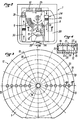
- La figure 2 est une vue de dessus simplifiée du dispositif selon l'invention.
- La figure 3 est une vue de dessus d'un disque à alvéoles utilisé dans le dispositif selon l'invention.
- La figure 4 est une coupe selon la ligne IV-IV de la figure 3.
- La figure 5 montre en perspective un porte-échantillons pour le dispositif selon l'invention.
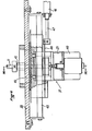
- Les figures 6 et 7 sont des coupes respectivement selon les lignes VI-VI et VII-VII de la figure 2.
- La figure 8 illustre schématiquement le processus de lecture des agglutinats.
- Sur ces figures des références identiques désignent des éléments identiques.
- L'installation pour la reconnaissance des groupes sanguins, montrée par la figure 1, comporte un dispositif 1 selon l'invention pour la détection et la quantification d'agglutinats, associé à un dispositif de visualisation 2, à un dispositif de commande 3 et à un dispositif d'impression 4. L'ensemble de l'installation est pilotée par un microprocesseur (non représenté) selon un processus non décrit ci-après.
- Comme le montré également la figure 2, le dispositif 1 selon l'invention comporte un bras oscillant horizontal 5 susceptible de tourner autour d'un axe vertical 6. Le bras 5 porte une pluralité de seringues verticales 7, dont les pistons peuvent être actionnés pour aspirer ou refouler un liquide. Lorsque le bras 5 oscille autour de l'axe vertical 6, les seringues 7 balayent une zone annulaire 8.
- Dans cette zone annulaire 8 sont prévus des récipients à réactifs 9 dans chacun desquels les seringues verticales 7 peuvent prélever un réactif et un récipient de rinçage 10.
- Par ailleurs, le dispositif 1 comporte un axe vertical 11 susceptible d'entraîner en rotation un disque 12 de matière transparente dans lequel sont pratiqués des alvéoles 13. Par exemple, comme le montrent les figures 3 et 4, le disque 12 comporte un disque supérieur 14 et un disque inférieur 15 superposés et assemblés par exemple par collage. Les disques 14 et 15 sont en une matière synthétique transparente et sont pourvus en leur centre de trous 16 pour permettre le passage de l'arbre rotatif d'entraînement 11 lorsque les disques 1 et 2 sont superposés et solidarisés.
- Le disque supérieur 14 est pourvu d'une pluralité de trous traversants 17 dont les axes 22 orthogonaux au plan du disque 14 sont répartis en une pluralité de points 18 se trouvant à l'intersection de rayons 19 et de cercles concentriques 20. Par ailleurs, chaque trou 17 est évasé vers le haut.
- A des fins de clarté du dessin, sur la figure 3, seuls quelques trous 17 ont été représentés.
- Le disque transparent inférieur 15 comporte une pluralité de trous borgnes 21 dont les axes 23 sont répartis en une pluralité de points se trouvant à l'intersection de rayons et de cercles concentriques et sont décalés par rapport aux axes 22.Les trous borgnes 21 sont, dans le disque inférieur 15, prolongés en direction des trous 17, par un trou de communication 24 à fond plat, suffisamment allongé pour que le bord supérieur des entonnoirs 17 se trouve à l'extérieur du récipient 21, ou tout au moins dégage sur le fond de celui-ci un champ de vision 25 recouvrant pratiquement la plus grande partie dudit fond.
- La zone annulaire 8 de balayage des seringues 7 coupe le disque 12 de sorte qu'il est possible de remplir tous les alvéoles 13 (ou récipient 13) disposés sur un rayon 19 du disque 12, en doses de réactifs provenant des réservoirs 9 en introduisant les aiguilles de seringues 7 dans les entonnoirs correspondants 17, le liquide traversant alors les trous 17 et 24 pour parvenir jusqu'au trou borgne 21. De la même façon, il est possible d'introduire dans les récipients 13 des doses de liquides provenant de réservoirs 26 se trouvant dans la zone 8. Lorsqu'une agitation ou une centrifugation est nécessaire, il suffit de soumettre le disque 12 à ce mouvement et, puisque les trous 21 sont obturés par le disque 14 il n'y a aucun risque que le liquide contenu dans les récipients 13 s'échappe vers l'extérieur.
- Les réservoirs 26 sont constitués (voir la figure 5) de blocs transparents 27 portant de façon amovible des tubes 28 qui contiennent des échantillons de sang provenant de donneurs et dans lesquels sont éventuellement pratiqués des évidements 29 contenant des dilutions des liquides desdits tubes.
- Les réservoirs 26 sont introduits dans le dispositif 1 par un convoyeur 30 qui les fait passer successivement à différents postes de traitement 31, 32 et 33, avant de les amener au poste 34 où les seringues 7 du bras 5 peuvent prélever le liquide qu'ils-contiennent.
- Ainsi, chaque alvéole 13 du disque 12 peut servir de récipient de réaction entre un liquide provenant d'un réservoir 26 et un réactif provenant d'un réservoir 9.
- Pour examiner le résultat de l'agglutination qui peut en résulter, le dispositif 1 comporte une barrette 35 de diodes CCD, disposée sous le disque 12 en regard d'un dispositif d'éclairage 36. La barrette 35 et le dispositif d'éclairage 36 sont opposés au bras 5 par rapport à l'axe 11 et la barrette 35 est orthogonale au plan vertical défini par les axes 6 et 11.
- La barrette 35 examine par transparence le fond 25 de chaque alvéole 13 selon m observations décalées chacune d'un pas. Pour que tous les alvéoles 13 d'un rayon 19 du disque 12 puissent être examinés chacun en m pas, l'axe 11 dudit disque est rendu mobile en translation horizontale, orthogonalement à ladite barrette 35.
- A cette fin, les figures 6 et 7 montrent que l'axe 11 du disque 12 est solidaire d'un chariot 37 mobile par rapport à la plaque de base 38 du dispositif. Ce chariot 37 comporte un bâti 39 portant un moteur 40 et un palier lisse 41 pour l'axe 11. L'arbre de sortie du moteur 40 entraîne en rotation une poulie 42 qui est reliée à une poulie 43 calée sur l'axe 11, par l'intermédiaire d'une courroie crantée 44. Le chariot 37 est guidé en translation par un rail 45 et il se déplace sous l'action d'un vérin 46, dont la tige 47 est relié au chariot 37 par une tige 48.
- Ainsi, l'axe 11 peut coulisser dans une fente 49, de la plaque de base 38, parallèle au rail 45 et orthogonal à la barrette 35 de diodes CCD.
- Le chariot 37 peut porter de plus un vibreur 49 destiné à animer épisodiquement, à l'encontre de l'action d'un ressort 50, l'axe 11 d'un mouvement alternatif parallèlement à son axe, afin d'agiter éventuellement le liquide contenu dans les alvéoles 13 du disque 12.
- Quand les alvéoles 131 à 13p du rayon 19 se trouvant dans le plan défini par les axes 6 et 11 doivent être lus par l'agencement 35 pour détecter et quantifier les agglutinations (voir la figure 8), le disque 12 est avancé par le vérin 46 dans le sens de la flèche F1 pour que l'agencement 35 soit à l'aplomb de la limite externe 51 du champ 25 du fond du premier alvéole 131.Puis, pas à pas le vérin est déplacé m fois pour que les n éléments photosensibles de l'agencement 35 examine en n x m points ledits champs 25. Lorsque la lecture du champ 25 de l'alvéole 131 est terminée, le vérin 46 déplace l'axe 11, toujours dans le sens F1, de façon que la limite externe 52 du champ 25 du fond du second alvéole 132 arrive à l'aplomb des éléments photosensibles de l'agencement 35. Ce second alvéole 132 est lu de façon identique et le processus se continue jusqu'à la lecture complète de l'alvéole 13p. Après celle-ci, le vérin 46 ramène l'axe 11 dans sa position initiale (flèche F2).
Claims (9)
caractérisé en ce que le bras oscillant (5) porte autant de moyens (7) de prélèvement et de restitution qu'un rayon (19) du disque (12) comporte d'alvéoles (13).
caractérisé en ce que l'agencement linéaire (35) d'éléments photosensibles est disposé orthogonalement au plan vertical passant par les axes verticaux (11) du disque (12) et (6) du bras oscillant (5), du côté de l'axe (11) du disque (12) opposé audit bras oscillant (5).
caractérisé en ce que les réservoirs (9) à réactifs sont disposés à poste fixe d'un côté du plan vertical défini par les axes verticaux (6 et 11) du bras oscillant (5) et du disque (12, tandis que les emplacements de prélèvement (34) des réservoirs (26) à liquides à tester sont disposés de l'autre côté dudit plan vertical.
caractérisé en ce que les réservoirs (26) contenant les liquides à tester sont mobiles et amenés à l'emplacement de prélèvement (34) par un transporteur.
caractérisé en ce que l'agencement (35) d'éléments photosensibles est une barrette de diodes CCD.
caractérisé en ce que l'axe (11) du disque (12) est solidaire d'un chariot (37), mobile en coulissement le long d'un rail (45) et portant un moteur (40) pour l'entraînement en rotation dudit axe (11).
caractérisé en ce que le chariot (37) est mû par un vérin .
caractérisé en ce que l'axe (11) du disque (12) est monté dans un palier lisse solidaire du chariot (37) et en ce qu'un vibreur (49) peut faire vibrer l'axe (11) longitudinalement.
Priority Applications (1)
| Application Number | Priority Date | Filing Date | Title |
|---|---|---|---|
| AT83402000T ATE26487T1 (de) | 1982-10-21 | 1983-10-13 | Einrichtung zur feststellung und zahlenmaessigen auswertung von agglutinaten. |
Applications Claiming Priority (2)
| Application Number | Priority Date | Filing Date | Title |
|---|---|---|---|
| FR8217635A FR2535058B1 (fr) | 1982-10-21 | 1982-10-21 | Dispositif pour la detection et la quantification d'agglutinats |
| FR8217635 | 1982-10-21 |
Publications (3)
| Publication Number | Publication Date |
|---|---|
| EP0107580A2 true EP0107580A2 (fr) | 1984-05-02 |
| EP0107580A3 EP0107580A3 (en) | 1984-12-27 |
| EP0107580B1 EP0107580B1 (fr) | 1987-04-08 |
Family
ID=9278460
Family Applications (1)
| Application Number | Title | Priority Date | Filing Date |
|---|---|---|---|
| EP83402000A Expired EP0107580B1 (fr) | 1982-10-21 | 1983-10-13 | Dispositif pour la détection et la quantification d'agglutinats |
Country Status (6)
| Country | Link |
|---|---|
| US (1) | US4687638A (fr) |
| EP (1) | EP0107580B1 (fr) |
| JP (1) | JPS59132338A (fr) |
| AT (1) | ATE26487T1 (fr) |
| DE (1) | DE3370864D1 (fr) |
| FR (1) | FR2535058B1 (fr) |
Cited By (4)
| Publication number | Priority date | Publication date | Assignee | Title |
|---|---|---|---|---|
| FR2607258A1 (fr) * | 1986-11-24 | 1988-05-27 | Materiel Biomedical | Dispositif et recipient pour la detection et la quantification d'agglutinats |
| EP0221779A3 (en) * | 1985-10-31 | 1989-10-11 | Genetic Systems Corporation | Photo densitometer |
| EP0486978A1 (fr) * | 1990-11-23 | 1992-05-27 | BEHRINGWERKE Aktiengesellschaft | Méthode et dispositif pour évaluation quantitative de réactions d'agglutination |
| WO1996007890A1 (fr) * | 1993-03-03 | 1996-03-14 | Deutsches Rotes Kreuz Blutspendedienst Baden-Württemberg Gemeinnützige Gmbh | Procede de detection photometrique d'une reaction d'agglutination |
Families Citing this family (34)
| Publication number | Priority date | Publication date | Assignee | Title |
|---|---|---|---|---|
| JP2750605B2 (ja) * | 1989-05-17 | 1998-05-13 | スズキ株式会社 | 粒子凝集パターン判定方法 |
| US5540890A (en) * | 1992-03-27 | 1996-07-30 | Abbott Laboratories | Capped-closure for a container |
| US5376313A (en) * | 1992-03-27 | 1994-12-27 | Abbott Laboratories | Injection molding a plastic assay cuvette having low birefringence |
| US5507410A (en) * | 1992-03-27 | 1996-04-16 | Abbott Laboratories | Meia cartridge feeder |
| US5575978A (en) * | 1992-03-27 | 1996-11-19 | Abbott Laboratories | Sample container segment assembly |
| US6190617B1 (en) | 1992-03-27 | 2001-02-20 | Abbott Laboratories | Sample container segment assembly |
| US5536471A (en) * | 1992-03-27 | 1996-07-16 | Abbott Laboratories | Syringe with bubble flushing |
| US5646049A (en) * | 1992-03-27 | 1997-07-08 | Abbott Laboratories | Scheduling operation of an automated analytical system |
| US5578494A (en) * | 1992-03-27 | 1996-11-26 | Abbott Laboratories | Cap actuator for opening and closing a container |
| US5635364A (en) * | 1992-03-27 | 1997-06-03 | Abbott Laboratories | Assay verification control for an automated analytical system |
| US5960160A (en) * | 1992-03-27 | 1999-09-28 | Abbott Laboratories | Liquid heater assembly with a pair temperature controlled electric heating elements and a coiled tube therebetween |
| US5610069A (en) * | 1992-03-27 | 1997-03-11 | Abbott Laboratories | Apparatus and method for washing clinical apparatus |
| US5605665A (en) * | 1992-03-27 | 1997-02-25 | Abbott Laboratories | Reaction vessel |
| US5627522A (en) * | 1992-03-27 | 1997-05-06 | Abbott Laboratories | Automated liquid level sensing system |
| US5314825A (en) * | 1992-07-16 | 1994-05-24 | Schiapparelli Biosystems, Inc. | Chemical analyzer |
| US6327031B1 (en) * | 1998-09-18 | 2001-12-04 | Burstein Technologies, Inc. | Apparatus and semi-reflective optical system for carrying out analysis of samples |
| US5856194A (en) | 1996-09-19 | 1999-01-05 | Abbott Laboratories | Method for determination of item of interest in a sample |
| US5795784A (en) | 1996-09-19 | 1998-08-18 | Abbott Laboratories | Method of performing a process for determining an item of interest in a sample |
| BR9809154B1 (pt) * | 1997-05-23 | 2012-09-04 | aparelho e sistema de teste microbiológico diagnóstico. | |
| AU3212400A (en) * | 1999-01-22 | 2000-08-07 | Human Genome Sciences, Inc. | Metalloproteinase adam 22 |
| WO2002044695A1 (fr) * | 2000-11-16 | 2002-06-06 | Burstein Technologies, Inc. | Methodes et appareils destines a la detection et au denombrement de lymphocytes utilisant des biodisques optiques |
| US7141416B2 (en) * | 2001-07-12 | 2006-11-28 | Burstein Technologies, Inc. | Multi-purpose optical analysis optical bio-disc for conducting assays and various reporting agents for use therewith |
| US20030129665A1 (en) * | 2001-08-30 | 2003-07-10 | Selvan Gowri Pyapali | Methods for qualitative and quantitative analysis of cells and related optical bio-disc systems |
| US20030143637A1 (en) * | 2001-08-31 | 2003-07-31 | Selvan Gowri Pyapali | Capture layer assemblies for cellular assays including related optical analysis discs and methods |
| AU2002335715A1 (en) * | 2001-09-07 | 2003-03-24 | Burstein Technologies, Inc. | Optical bio-disc systems for nuclear morphology based identification |
| JP2005502369A (ja) * | 2001-09-12 | 2005-01-27 | バースタイン テクノロジーズ,インコーポレイティド | 分画細胞計数方法ならびにそれを実行するための関連する装置およびソフトウェア |
| WO2003043403A2 (fr) * | 2001-11-19 | 2003-05-30 | Burstein Technologies, Inc. | Methode et appareil de typage sanguin a l'aide de bio-disques |
| AU2002352735A1 (en) * | 2001-11-20 | 2003-06-10 | Burstein Technologies, Inc. | Optical bio-discs and microfluidic devices for analysis of cells |
| US20040246252A1 (en) * | 2002-01-14 | 2004-12-09 | Morrow Jesse James | Method and apparatus for visualizing data |
| WO2003065358A2 (fr) * | 2002-01-28 | 2003-08-07 | Burstein Technologies, Inc. | Procedes et appareil pour le declenchement logique |
| US20050003459A1 (en) * | 2002-01-30 | 2005-01-06 | Krutzik Siegfried Richard | Multi-purpose optical analysis disc for conducting assays and related methods for attaching capture agents |
| AU2003209372B2 (en) * | 2002-01-31 | 2009-02-19 | Burstein Technologies, Inc. | Method for triggering through disc grooves and related optical analysis discs and system |
| US7218394B2 (en) * | 2004-07-29 | 2007-05-15 | Matsushita Electric Industrial Co., Ltd. | Liquid specimen analysis disk assembly |
| PT106871B (pt) * | 2013-04-08 | 2015-06-15 | Univ Do Minho | Dispositivo e método de análises de sangue por processamento de imagem |
Family Cites Families (15)
| Publication number | Priority date | Publication date | Assignee | Title |
|---|---|---|---|---|
| US3193358A (en) * | 1962-07-02 | 1965-07-06 | Warner Lambert Pharmacentical | Automated analytical apparatus |
| US3488156A (en) * | 1966-02-23 | 1970-01-06 | Lab Line Biomedical Products I | Automatic agglutinometer |
| US3883308A (en) * | 1967-05-12 | 1975-05-13 | Centre Nat Rech Scient | Apparatus for analysing liquid substances likely to form agglutinates |
| US3489525A (en) * | 1967-08-25 | 1970-01-13 | Scientific Industries | System of automatic analysis |
| US3607099A (en) * | 1969-03-11 | 1971-09-21 | Medical Laboratory Automation | Prothrombin time measuring apparatus |
| US3636777A (en) * | 1969-09-16 | 1972-01-25 | Vision Lab Inc | Laboratory beaker transporter and elevator |
| US3790346A (en) * | 1971-07-30 | 1974-02-05 | Sherwood Medical Ind Inc | Heating system |
| DE2553129A1 (de) * | 1974-11-26 | 1976-06-10 | Giuseppe Piazza | Analysiervorrichtung |
| US4285906A (en) * | 1979-05-11 | 1981-08-25 | Warner-Lambert Company | Rotatable detector |
| FR2475735A1 (fr) * | 1980-02-11 | 1981-08-14 | Faure Jean Marie | Analyseurs et procede pour la determination automatique de differents parametres sur de echantillons liquides |
| SE8004687L (sv) * | 1980-06-25 | 1981-12-26 | Clinicon Ab | Automatisk analysapparat |
| FR2488691A1 (fr) * | 1980-08-14 | 1982-02-19 | Commissariat Energie Atomique | Procede et dispositif pour la detection et la quantification d'agglutinats en temps reel |
| US4387164A (en) * | 1980-11-05 | 1983-06-07 | Fmc Corporation | Method and apparatus for chemical analysis using reactive reagents dispersed in soluble film |
| US4363245A (en) * | 1980-11-18 | 1982-12-14 | Peerless Electronics Research Corp. | Sampling apparatus |
| US4699767A (en) * | 1982-02-24 | 1987-10-13 | Olympus Optical Company, Ltd. | Liquid transfer apparatus for automatic analyzers |
-
1982
- 1982-10-21 FR FR8217635A patent/FR2535058B1/fr not_active Expired
-
1983
- 1983-10-13 EP EP83402000A patent/EP0107580B1/fr not_active Expired
- 1983-10-13 AT AT83402000T patent/ATE26487T1/de active
- 1983-10-13 DE DE8383402000T patent/DE3370864D1/de not_active Expired
- 1983-10-21 JP JP58198183A patent/JPS59132338A/ja active Granted
-
1985
- 1985-09-30 US US06/781,210 patent/US4687638A/en not_active Expired - Fee Related
Cited By (6)
| Publication number | Priority date | Publication date | Assignee | Title |
|---|---|---|---|---|
| EP0221779A3 (en) * | 1985-10-31 | 1989-10-11 | Genetic Systems Corporation | Photo densitometer |
| FR2607258A1 (fr) * | 1986-11-24 | 1988-05-27 | Materiel Biomedical | Dispositif et recipient pour la detection et la quantification d'agglutinats |
| EP0271398A1 (fr) * | 1986-11-24 | 1988-06-15 | LE MATERIEL BIOMEDICAL Société à Responsabilité Limitée dite: | Dispositif et récipient pour la détection et la quantification d'agglutinats |
| EP0486978A1 (fr) * | 1990-11-23 | 1992-05-27 | BEHRINGWERKE Aktiengesellschaft | Méthode et dispositif pour évaluation quantitative de réactions d'agglutination |
| US5628963A (en) * | 1990-11-23 | 1997-05-13 | Behringwerke Aktiengesellschaft | Apparatus for quanitative evaluation of agglutination reactions |
| WO1996007890A1 (fr) * | 1993-03-03 | 1996-03-14 | Deutsches Rotes Kreuz Blutspendedienst Baden-Württemberg Gemeinnützige Gmbh | Procede de detection photometrique d'une reaction d'agglutination |
Also Published As
| Publication number | Publication date |
|---|---|
| FR2535058A1 (fr) | 1984-04-27 |
| FR2535058B1 (fr) | 1987-08-21 |
| ATE26487T1 (de) | 1987-04-15 |
| EP0107580B1 (fr) | 1987-04-08 |
| US4687638A (en) | 1987-08-18 |
| JPS59132338A (ja) | 1984-07-30 |
| JPH029709B2 (fr) | 1990-03-05 |
| EP0107580A3 (en) | 1984-12-27 |
| DE3370864D1 (en) | 1987-05-14 |
Similar Documents
| Publication | Publication Date | Title |
|---|---|---|
| EP0107580B1 (fr) | Dispositif pour la détection et la quantification d'agglutinats | |
| EP0129450B1 (fr) | Procédé et dispositif pour la détection et la quantification d'agglutinats | |
| EP0445053A1 (fr) | Automate analyseur pour le groupage sanguin | |
| EP2917741B1 (fr) | Dispositif d'analyse pour diagnostic in vitro | |
| CA2639147C (fr) | Cuvette unitaire pour l'analyse d'un fluide biologique, et dispositif automatique d'analyse in vitro | |
| FR2810407A1 (fr) | Appareil pour l'analyse d'echantillons | |
| EP1086363B1 (fr) | Appareil d'analyse automatique utilisable pour la determination du temps de coagulation du sang | |
| JP6552597B2 (ja) | マイクロプレート | |
| US6162399A (en) | Universal apparatus for clinical analysis | |
| EP0286536B1 (fr) | Transporteur rotatif à avance pas-à-pas et installation de prélèvement d'échantillons liquides comportant un tel transporteur | |
| EP0726453A1 (fr) | Dispositif d'agitation et de prélèvement d'échantillons de produits sanguins dans des tubes regroupés dans des cassettes | |
| EP0046430A1 (fr) | Procédé pour la détection et la quantification d'agglutinats en temps réel | |
| EP1470425B1 (fr) | Dispositif pour l'analyse automatisee d'un echantillon liquide | |
| EP0301583B1 (fr) | Appareil pour l'analyse immunologique automatique | |
| JPS6020695B2 (ja) | 液体中の固形物の検査装置 | |
| EP0363265A1 (fr) | Analyseur automatique d'échantillons par colorimétrie, notamment pour les analyses sanguines | |
| US20020042141A1 (en) | Apparatus for the preparation and the performance of sedimentation velocity tests on organic liquids and other substances | |
| FR2579755A1 (fr) | Procede pour la realisation d'analyses medicales d'un echantillon liquide a l'aide de reactifs secs, et dispositif pour la mise en oeuvre du procede | |
| EP0072284B1 (fr) | Support de réaction à récipients multiples pour tests de doses liquides | |
| EP0169794A1 (fr) | Coagulomètre et procédé de mesure du temps de coagulation d'échantillons de produits fluides | |
| EP1042663B1 (fr) | Dispositif, procede et appareil de mise en oeuvre du procede, pour effectuer un dosage d'au moins un composant particulier dans un echantillon de produit | |
| EP3423840B1 (fr) | Système d'analyse automatique pour diagnostic in vitro | |
| EP0271398B1 (fr) | Dispositif et récipient pour la détection et la quantification d'agglutinats | |
| EP0176643A1 (fr) | Dispositif d'actionnement pour un automatisme comportant une pluralité d'organes mobiles combinés | |
| FR2726653A1 (fr) | Dispositif pour la collecte ou la distribution d'echatillons liquides |
Legal Events
| Date | Code | Title | Description |
|---|---|---|---|
| PUAI | Public reference made under article 153(3) epc to a published international application that has entered the european phase |
Free format text: ORIGINAL CODE: 0009012 |
|
| AK | Designated contracting states |
Designated state(s): AT BE CH DE GB IT LI LU NL SE |
|
| PUAL | Search report despatched |
Free format text: ORIGINAL CODE: 0009013 |
|
| AK | Designated contracting states |
Designated state(s): AT BE CH DE GB IT LI LU NL SE |
|
| 17P | Request for examination filed |
Effective date: 19850307 |
|
| 17Q | First examination report despatched |
Effective date: 19860605 |
|
| GRAA | (expected) grant |
Free format text: ORIGINAL CODE: 0009210 |
|
| AK | Designated contracting states |
Kind code of ref document: B1 Designated state(s): AT BE CH DE GB IT LI LU NL SE |
|
| REF | Corresponds to: |
Ref document number: 26487 Country of ref document: AT Date of ref document: 19870415 Kind code of ref document: T |
|
| REF | Corresponds to: |
Ref document number: 3370864 Country of ref document: DE Date of ref document: 19870514 |
|
| ITF | It: translation for a ep patent filed | ||
| PLBE | No opposition filed within time limit |
Free format text: ORIGINAL CODE: 0009261 |
|
| STAA | Information on the status of an ep patent application or granted ep patent |
Free format text: STATUS: NO OPPOSITION FILED WITHIN TIME LIMIT |
|
| 26N | No opposition filed | ||
| ITTA | It: last paid annual fee | ||
| EPTA | Lu: last paid annual fee | ||
| EAL | Se: european patent in force in sweden |
Ref document number: 83402000.0 |
|
| PGFP | Annual fee paid to national office [announced via postgrant information from national office to epo] |
Ref country code: LU Payment date: 19951001 Year of fee payment: 13 |
|
| PGFP | Annual fee paid to national office [announced via postgrant information from national office to epo] |
Ref country code: CH Payment date: 19951002 Year of fee payment: 13 |
|
| PGFP | Annual fee paid to national office [announced via postgrant information from national office to epo] |
Ref country code: GB Payment date: 19951003 Year of fee payment: 13 |
|
| PGFP | Annual fee paid to national office [announced via postgrant information from national office to epo] |
Ref country code: SE Payment date: 19951010 Year of fee payment: 13 |
|
| PGFP | Annual fee paid to national office [announced via postgrant information from national office to epo] |
Ref country code: AT Payment date: 19951018 Year of fee payment: 13 |
|
| PGFP | Annual fee paid to national office [announced via postgrant information from national office to epo] |
Ref country code: DE Payment date: 19951023 Year of fee payment: 13 |
|
| PGFP | Annual fee paid to national office [announced via postgrant information from national office to epo] |
Ref country code: NL Payment date: 19951031 Year of fee payment: 13 |
|
| BERE | Be: lapsed |
Owner name: LE MATERIEL BIOMEDICAL Effective date: 19951031 |
|
| PGFP | Annual fee paid to national office [announced via postgrant information from national office to epo] |
Ref country code: BE Payment date: 19960906 Year of fee payment: 13 |
|
| PG25 | Lapsed in a contracting state [announced via postgrant information from national office to epo] |
Ref country code: LU Free format text: LAPSE BECAUSE OF NON-PAYMENT OF DUE FEES Effective date: 19961013 Ref country code: GB Effective date: 19961013 Ref country code: AT Effective date: 19961013 |
|
| PG25 | Lapsed in a contracting state [announced via postgrant information from national office to epo] |
Ref country code: SE Effective date: 19961014 |
|
| PG25 | Lapsed in a contracting state [announced via postgrant information from national office to epo] |
Ref country code: LI Effective date: 19961031 Ref country code: CH Effective date: 19961031 Ref country code: BE Effective date: 19961031 |
|
| BERR | Be: reestablished | ||
| BERE | Be: lapsed |
Owner name: LE MATERIEL BIOMEDICAL Effective date: 19961031 |
|
| PG25 | Lapsed in a contracting state [announced via postgrant information from national office to epo] |
Ref country code: NL Effective date: 19970501 |
|
| GBPC | Gb: european patent ceased through non-payment of renewal fee |
Effective date: 19961013 |
|
| REG | Reference to a national code |
Ref country code: CH Ref legal event code: PL |
|
| NLV4 | Nl: lapsed or anulled due to non-payment of the annual fee |
Effective date: 19970501 |
|
| PG25 | Lapsed in a contracting state [announced via postgrant information from national office to epo] |
Ref country code: DE Effective date: 19970701 |
|
| EUG | Se: european patent has lapsed |
Ref document number: 83402000.0 |