EP0107663B1 - Querbalkenteil für eine tür - Google Patents
Querbalkenteil für eine tür Download PDFInfo
- Publication number
- EP0107663B1 EP0107663B1 EP19820903439 EP82903439A EP0107663B1 EP 0107663 B1 EP0107663 B1 EP 0107663B1 EP 19820903439 EP19820903439 EP 19820903439 EP 82903439 A EP82903439 A EP 82903439A EP 0107663 B1 EP0107663 B1 EP 0107663B1
- Authority
- EP
- European Patent Office
- Prior art keywords
- transom
- energy
- transom member
- sensing device
- cover member
- Prior art date
- Legal status (The legal status is an assumption and is not a legal conclusion. Google has not performed a legal analysis and makes no representation as to the accuracy of the status listed.)
- Expired
Links
- 230000005855 radiation Effects 0.000 claims description 14
- 230000005670 electromagnetic radiation Effects 0.000 claims description 9
- 229910052751 metal Inorganic materials 0.000 claims description 6
- 239000002184 metal Substances 0.000 claims description 6
- 239000004033 plastic Substances 0.000 claims description 5
- 229920003023 plastic Polymers 0.000 claims description 5
- 239000000463 material Substances 0.000 claims description 4
- 238000011179 visual inspection Methods 0.000 claims description 3
- 239000011324 bead Substances 0.000 description 15
- 238000001125 extrusion Methods 0.000 description 5
- 230000000717 retained effect Effects 0.000 description 3
- 239000004411 aluminium Substances 0.000 description 2
- 229910052782 aluminium Inorganic materials 0.000 description 2
- 238000010276 construction Methods 0.000 description 2
- 238000001514 detection method Methods 0.000 description 2
- 238000010586 diagram Methods 0.000 description 2
- 230000000694 effects Effects 0.000 description 2
- 230000035945 sensitivity Effects 0.000 description 2
- 150000001398 aluminium Chemical class 0.000 description 1
- XAGFODPZIPBFFR-UHFFFAOYSA-N aluminium Chemical compound [Al] XAGFODPZIPBFFR-UHFFFAOYSA-N 0.000 description 1
- 230000015572 biosynthetic process Effects 0.000 description 1
- 230000000295 complement effect Effects 0.000 description 1
- 230000003247 decreasing effect Effects 0.000 description 1
- 230000014759 maintenance of location Effects 0.000 description 1
- 230000004048 modification Effects 0.000 description 1
- 238000012986 modification Methods 0.000 description 1
- 238000009877 rendering Methods 0.000 description 1
- 229910001220 stainless steel Inorganic materials 0.000 description 1
- 239000010935 stainless steel Substances 0.000 description 1
Images


Classifications
-
- E—FIXED CONSTRUCTIONS
- E06—DOORS, WINDOWS, SHUTTERS, OR ROLLER BLINDS IN GENERAL; LADDERS
- E06B—FIXED OR MOVABLE CLOSURES FOR OPENINGS IN BUILDINGS, VEHICLES, FENCES OR LIKE ENCLOSURES IN GENERAL, e.g. DOORS, WINDOWS, BLINDS, GATES
- E06B1/00—Border constructions of openings in walls, floors, or ceilings; Frames to be rigidly mounted in such openings
- E06B1/04—Frames for doors, windows, or the like to be fixed in openings
- E06B1/34—Coverings, e.g. protecting against weather, for decorative purposes
-
- E—FIXED CONSTRUCTIONS
- E05—LOCKS; KEYS; WINDOW OR DOOR FITTINGS; SAFES
- E05D—HINGES OR SUSPENSION DEVICES FOR DOORS, WINDOWS OR WINGS
- E05D15/00—Suspension arrangements for wings
- E05D15/06—Suspension arrangements for wings for wings sliding horizontally more or less in their own plane
- E05D15/0621—Details, e.g. suspension or supporting guides
- E05D15/0626—Details, e.g. suspension or supporting guides for wings suspended at the top
- E05D15/0652—Tracks
-
- E—FIXED CONSTRUCTIONS
- E05—LOCKS; KEYS; WINDOW OR DOOR FITTINGS; SAFES
- E05F—DEVICES FOR MOVING WINGS INTO OPEN OR CLOSED POSITION; CHECKS FOR WINGS; WING FITTINGS NOT OTHERWISE PROVIDED FOR, CONCERNED WITH THE FUNCTIONING OF THE WING
- E05F15/00—Power-operated mechanisms for wings
- E05F15/70—Power-operated mechanisms for wings with automatic actuation
- E05F15/73—Power-operated mechanisms for wings with automatic actuation responsive to movement or presence of persons or objects
-
- E—FIXED CONSTRUCTIONS
- E06—DOORS, WINDOWS, SHUTTERS, OR ROLLER BLINDS IN GENERAL; LADDERS
- E06B—FIXED OR MOVABLE CLOSURES FOR OPENINGS IN BUILDINGS, VEHICLES, FENCES OR LIKE ENCLOSURES IN GENERAL, e.g. DOORS, WINDOWS, BLINDS, GATES
- E06B3/00—Window sashes, door leaves, or like elements for closing wall or like openings; Layout of fixed or moving closures, e.g. windows in wall or like openings; Features of rigidly-mounted outer frames relating to the mounting of wing frames
- E06B3/32—Arrangements of wings characterised by the manner of movement; Arrangements of movable wings in openings; Features of wings or frames relating solely to the manner of movement of the wing
- E06B3/34—Arrangements of wings characterised by the manner of movement; Arrangements of movable wings in openings; Features of wings or frames relating solely to the manner of movement of the wing with only one kind of movement
- E06B3/42—Sliding wings; Details of frames with respect to guiding
- E06B3/46—Horizontally-sliding wings
- E06B3/4636—Horizontally-sliding wings for doors
-
- E—FIXED CONSTRUCTIONS
- E05—LOCKS; KEYS; WINDOW OR DOOR FITTINGS; SAFES
- E05Y—INDEXING SCHEME ASSOCIATED WITH SUBCLASSES E05D AND E05F, RELATING TO CONSTRUCTION ELEMENTS, ELECTRIC CONTROL, POWER SUPPLY, POWER SIGNAL OR TRANSMISSION, USER INTERFACES, MOUNTING OR COUPLING, DETAILS, ACCESSORIES, AUXILIARY OPERATIONS NOT OTHERWISE PROVIDED FOR, APPLICATION THEREOF
- E05Y2201/00—Constructional elements; Accessories therefor
- E05Y2201/10—Covers; Housings
- E05Y2201/11—Covers
-
- E—FIXED CONSTRUCTIONS
- E05—LOCKS; KEYS; WINDOW OR DOOR FITTINGS; SAFES
- E05Y—INDEXING SCHEME ASSOCIATED WITH SUBCLASSES E05D AND E05F, RELATING TO CONSTRUCTION ELEMENTS, ELECTRIC CONTROL, POWER SUPPLY, POWER SIGNAL OR TRANSMISSION, USER INTERFACES, MOUNTING OR COUPLING, DETAILS, ACCESSORIES, AUXILIARY OPERATIONS NOT OTHERWISE PROVIDED FOR, APPLICATION THEREOF
- E05Y2201/00—Constructional elements; Accessories therefor
- E05Y2201/60—Suspension or transmission members; Accessories therefor
- E05Y2201/606—Accessories therefor
- E05Y2201/61—Cooperation between suspension or transmission members
- E05Y2201/612—Cooperation between suspension or transmission members between carriers and rails
- E05Y2201/614—Anti-derailing means
-
- E—FIXED CONSTRUCTIONS
- E05—LOCKS; KEYS; WINDOW OR DOOR FITTINGS; SAFES
- E05Y—INDEXING SCHEME ASSOCIATED WITH SUBCLASSES E05D AND E05F, RELATING TO CONSTRUCTION ELEMENTS, ELECTRIC CONTROL, POWER SUPPLY, POWER SIGNAL OR TRANSMISSION, USER INTERFACES, MOUNTING OR COUPLING, DETAILS, ACCESSORIES, AUXILIARY OPERATIONS NOT OTHERWISE PROVIDED FOR, APPLICATION THEREOF
- E05Y2201/00—Constructional elements; Accessories therefor
- E05Y2201/60—Suspension or transmission members; Accessories therefor
- E05Y2201/622—Suspension or transmission members elements
- E05Y2201/688—Rollers
-
- E—FIXED CONSTRUCTIONS
- E05—LOCKS; KEYS; WINDOW OR DOOR FITTINGS; SAFES
- E05Y—INDEXING SCHEME ASSOCIATED WITH SUBCLASSES E05D AND E05F, RELATING TO CONSTRUCTION ELEMENTS, ELECTRIC CONTROL, POWER SUPPLY, POWER SIGNAL OR TRANSMISSION, USER INTERFACES, MOUNTING OR COUPLING, DETAILS, ACCESSORIES, AUXILIARY OPERATIONS NOT OTHERWISE PROVIDED FOR, APPLICATION THEREOF
- E05Y2600/00—Mounting or coupling arrangements for elements provided for in this subclass
- E05Y2600/10—Adjustable
-
- E—FIXED CONSTRUCTIONS
- E05—LOCKS; KEYS; WINDOW OR DOOR FITTINGS; SAFES
- E05Y—INDEXING SCHEME ASSOCIATED WITH SUBCLASSES E05D AND E05F, RELATING TO CONSTRUCTION ELEMENTS, ELECTRIC CONTROL, POWER SUPPLY, POWER SIGNAL OR TRANSMISSION, USER INTERFACES, MOUNTING OR COUPLING, DETAILS, ACCESSORIES, AUXILIARY OPERATIONS NOT OTHERWISE PROVIDED FOR, APPLICATION THEREOF
- E05Y2600/00—Mounting or coupling arrangements for elements provided for in this subclass
- E05Y2600/60—Mounting or coupling members; Accessories therefor
-
- E—FIXED CONSTRUCTIONS
- E05—LOCKS; KEYS; WINDOW OR DOOR FITTINGS; SAFES
- E05Y—INDEXING SCHEME ASSOCIATED WITH SUBCLASSES E05D AND E05F, RELATING TO CONSTRUCTION ELEMENTS, ELECTRIC CONTROL, POWER SUPPLY, POWER SIGNAL OR TRANSMISSION, USER INTERFACES, MOUNTING OR COUPLING, DETAILS, ACCESSORIES, AUXILIARY OPERATIONS NOT OTHERWISE PROVIDED FOR, APPLICATION THEREOF
- E05Y2800/00—Details, accessories and auxiliary operations not otherwise provided for
- E05Y2800/26—Form or shape
- E05Y2800/27—Profiles; Strips
-
- E—FIXED CONSTRUCTIONS
- E05—LOCKS; KEYS; WINDOW OR DOOR FITTINGS; SAFES
- E05Y—INDEXING SCHEME ASSOCIATED WITH SUBCLASSES E05D AND E05F, RELATING TO CONSTRUCTION ELEMENTS, ELECTRIC CONTROL, POWER SUPPLY, POWER SIGNAL OR TRANSMISSION, USER INTERFACES, MOUNTING OR COUPLING, DETAILS, ACCESSORIES, AUXILIARY OPERATIONS NOT OTHERWISE PROVIDED FOR, APPLICATION THEREOF
- E05Y2800/00—Details, accessories and auxiliary operations not otherwise provided for
- E05Y2800/26—Form or shape
- E05Y2800/29—Form or shape forming a unitary piece with another element
-
- E—FIXED CONSTRUCTIONS
- E05—LOCKS; KEYS; WINDOW OR DOOR FITTINGS; SAFES
- E05Y—INDEXING SCHEME ASSOCIATED WITH SUBCLASSES E05D AND E05F, RELATING TO CONSTRUCTION ELEMENTS, ELECTRIC CONTROL, POWER SUPPLY, POWER SIGNAL OR TRANSMISSION, USER INTERFACES, MOUNTING OR COUPLING, DETAILS, ACCESSORIES, AUXILIARY OPERATIONS NOT OTHERWISE PROVIDED FOR, APPLICATION THEREOF
- E05Y2900/00—Application of doors, windows, wings or fittings thereof
- E05Y2900/10—Application of doors, windows, wings or fittings thereof for buildings or parts thereof
- E05Y2900/13—Type of wing
- E05Y2900/132—Doors
Definitions
- This invention relates to a transom member for a movable door, having an elongate support member and a sensing device for sensing approach of a person towards the transom member, said sensing device including an energy detector for detecting energy from a person approaching the transom member.
- Transom members of the above kind are known, the sensing device normally being incorporated in a separate enclosure which is affixed to the exterior of the support member.
- Constructions such as the above have the disadvantage that vandals can readily appreciate, by visual inspection, the location of the sensing device and cause damage thereto such as by attempting to remove the sensing device from the transom member.
- the Publication FR-A-2,160,590 shows a door surround comprising an elongate support member and a cover member secured thereto.
- Publication FR-A-2,165,755 discloses a sensor device including an energy detector positioned above a door.
- the invention provides a transom member for a movable door, having an elongate support member and sensing device for sensing approach of a person towards the transom member, said sensing device including an energy detector for detecting energy from a person approaching the transom member, characterised in that said sensing device is positioned within a cavity defined between the support member and a cover member which is elongate in a lengthwise direction of the support member, with said detector being positioned to receive said energy through said cover member, and said cover member being formed of material opaque to visible radiation, whereby the location of the sensing means within the cavity and along the length of the cover member is not apparent from external visual inspection of the transom member.
- the sensing device When the sensing device is mounted in the transom member in the above way, it is not easy to determine the precise location of the sensing device and vandals may not notice that such sensing device is provided. Furthermore they may be deterred from attempting to remove the sensing device because breaking of the cover member at a random location may not provide immediate access to the sensing device.
- a sliding door assembly 8 is shown therein as including a transom member 10 which in use extends above a door opening.
- the transom member includes a lengthwise extending track member 112 and a carriage 106 is supported for lengthwise movement along the track member by means of support wheels 110.
- a door panel 108 which is normally aluminium framed, is hangingly supported from the carriage 106 for slidable movement with the carriage in its own plane.
- the assembly 8 is arranged for power actuation.
- the precise means whereby this actuation is effected may be in accordance with well known practice and does not form part of this invention.
- the transom member 10 carries at its inner face a support plate 105 to which an electric motor 107 (shown by phantom lines) is mounted.
- Motor 107 is arranged for turning one of two sprocket wheels mounted at opposite ends of a transom.
- One of the sprocket wheels is shown by phantom lines, being designated by reference numeral 109 in Figure 1.
- a chain 111 (shown in phantom) runs in a loop around the sprocket wheels, presenting, two runs one above the other of which the upper run only being visible.
- the lower run is connected to an extension 113 (also shown by phantom lines) on carriage 106 so that by operating the motor 107 sprocket 109 is turned to move the chairi 111 around its loop thus moving the carriage 106 and panel
- a sliding door assembly having the features as described above is disclosed in more detail, in for example, Australian Patent Specification 467591 the contents which are hereby incorporated to form part of the disclosure of the present specification.
- the transom member 10 of Figure 1 includes a support member 12 in the form of an aluminium extrusion.
- the support member 12 includes an upstanding front web portion 14, a rearwardly extending upper flange 15 and a rearwardly extending lower flange 16.
- Flange 16 extends from portion 14 at a location a short distance above the lower edge of portion 14 and includes a downwardly extending end portion 16a which extends generally parallel to portion 14.
- Flange end portion 16a extends downwardly somewhat below the lower edge of web portion 14.
- a cavity 18 is defined between portion 16a and the lower part of web portion 14.
- a sensing device 20 is positioned within cavity 18, being carried by a bracket 22 which is itself secured to the flange end portion 16a of flanges 16 on member 12.
- Member 12 includes an elongate slot 24 formed between two forwardly extending ribs 24a on flange end portion 16a.
- a bolt 26 has its head maintained captive in slot 24 but freely slidable along the length of the slot. The shank of the bolt 26 extends outwardly from the slot 24 and through an opening (not shown) in bracket 22.
- a nut 28 is threadedly engaged on the free end of bolt 24 and tightened down so as to lock the bracket 22 in position at any desired location along the length of the slot 24. By releasing the nut 28 it is possible to so loosen the connection between the bracket and member 12 as to permit the bolt, bracket 22 and sensing device to move along slot 24.
- An L-shaped section plastics cover member 30 is removably positioned on member 12.
- Member 30 defines a first upstanding flange 32 and a second, lower, rearwardly extending flange 33.
- Flange 32 extends downwardly from the lower edge of web portion 14 of member 12 and flange 33 extends rearwardly to a position adjacent the lower end of flange end portion 16a on member 12.
- Cover member 30 is a snap-fit on to the member 12.
- the flange 32 carries two rearwardly extending ridges 35, 37 which extend lengthwise of the member 30 and of which ridge 35 is received in a slot 38 in web portion 14 of member 12 and ridge 37 resiliently engages the lower edge of the web portion 14 of member 12.
- Flange 33 carries an upstanding inverted L-shaped flange 40 having an upper portion 40a which extends rearwardly. Portion 40a and a portion 33a of flange 33 extending rearwardly from the location of flange 40 resiliently grip therebetween an outstanding bead 44 defined on flange end portion 16a on member 12. Portion 33a also defines an upstanding beading 46 which is received in a lengthwise extending slot 48 in the base of flange end portion 16a on member 12.
- the member 30 is positioned on member 12 by moving it from left to right as shown in the drawing so that, on the one hand, the ridges 35 and 37 are, respectively, entered into the slot 38 and engaged with with lower surface of web portion 14 of member 12 while, on the other hand, the bead 44 is forced between the portion 33a of flange 33 and portion 40a of flange 40.
- the portion 33a is downwardly resiliently biased as the beading 46 passes the underside of bead 44 until the beading 46 is aligned with the groove 48 whereupon upward movement of the portion 33a can occur to neatly fit the beading 46 into the groove 48.
- Cover member 30 may if desired be further secured in position by means of machine screws 50 extending through openings in the flange portion 33a and into an elongate slot 52 in the lower face of flange end portion 16a on member 12.
- the groove 52 has opposed side faces of undulating configuration such that transverse sections of the groove 52 correspond to axial sections of a screw thread so that the screws 50 are accommodated in the groove by threaded engagement therewith.
- a metal facia 60 is removably hinged to the member 12. More particularly, the member 12 has an elongate rubber lined groove 56 running along the upper surface of the flange 15 thereof and the facia 60 has a hooked upper flange 62 which is hingedly engaged with the groove 56. From flange 62, the facia 60 defines a downwardly depending web 64 which towards its lower end first extends forwardly at a portion 64a thereof and then extends downwardly, at a portion 64b thereof. Web 64 also includes a rearwardly extending flange 64c extending from the lower edge of web portion 64b. Web portion 64a has a groove 70 formed in the underside thereof and flange 64c has an upwardly extending bead 72 formed therealong at its free edge.
- a second cover member 80 of plastics material is removably engaged with facia 60.
- Member 80 is of generally L-shaped configuration having an upstanding web portion 82 and a lower web portion 84 which extends forwardly from portion 82 to a location just forward of and immediately below flange 64c of web 64.
- a forwardly extending beaded flange 88 provided on the upper end of portion 82 of member 80 extends into the aforementioned groove 70 in the underside of web portion 64c on facia 60.
- Lower web portion 84 carries a forwardly extending flange 86 on its upper surface this being of hooked formation arranged to be engaged over bead 72 so that the bead 72 is retained and gripped between the lower web portion 84 of member 80 and the flange 86.
- a second sensing device 100 is positioned in a cavity 102 defined between the cover member 80 and the portions 64a, 64b of web 64.
- the carriage 106 for supporting the sliding door panel 108 is movable lengthwise of the transom member 10 within this space.
- the track member 112 on which the wheels 110 of the carriage 106 run is mounted on flanged end portion 16a of member 12. Track member 112 is held in position by a retainer strip 114 bolted to member 12.
- the sensing devices 20 and 100 are of similar form each being of a known type operable on application of electrical energy thereto to generate electromagnetic radiation which is directed outwardly away from transom member 10 to the respective side of member 10 to which that device is positioned, such radiation passing through the plastics cover members 30 and 80. Reflected radiation from the sensing devices, passing back from objects approaching the transom member and passing through the cover members 30, 80, is received by detectors within devices 20, 100.
- the devices 20 or 100 are coupled to the control circuitry for the door and include electrical circuitry operable on detection of changes in the received electromagnetic radiation occurring pursuant to approach of a person towards the transom member 10 to condition the control circuitry to cause the door panel 108 to move to an open position in a manner known per se.
- Figure 4 shows the electric circuit 300 of a suitable sensor device 20 or 100. Since, as indicated, the circuit designated by reference numeral 300 is conventional, its operation is not described in detail. Briefly, however, the circuit 300 includes a generator section 302 which operates to apply high frequency electric signal to a Gunn diode 303 which then emits microwave frequency electromagnetic radiation away from the sensor device.
- a detector section 304 includes a receiving diode 305 for detecting electromagnetic radiation and is able to detect variations in the frequency of the reflected radiation received by the sensor device. On detection of such variations, indicative of movement of an object in the field of radiated energy from diode 303, the detector section operates to energize a relay 307 the contacts 307a of which are interconnected into the electric circuit for controlling operation of the motor 107.
- the transom member 10 has a metal facia 104 removably clipped to the front surface of member 12 and arranged in the same plane as the flange 32 of member 30 and extending from the top of the member 12 down to the upper edge of flange 32 so as to give a neat appearance to the front of the transom member 10.
- the facia 60 is formed of pressed metal and, as shown, combines with the member 80 to present a neat appearance to the rear face of the facia.
- the transom member 200 of Figure 2 is similar to transom member 10, similar parts in Figures 1 and 2 having corresponding, but "primed", reference numerals. The following description of the transom member 200 is confined to differences between the members 10 and 200.
- the means whereby the cover member 30' and 80' of member 200 are attached differs as compared with transom member 10.
- the cover member 30' does not have the two ridges 35, 37 of cover member 30 and instead has a single inwardly extending ridge 201 on the front flange 32'.
- Ridge 201 is of arcuate cross-section and is retained in a complementary groove 202 in the support member 12' of transom member 200, so as to permit the member 30' to be swung forwardly, with the ridge 201 moving in groove 202.
- the direction of such swinging movement is indicated by the arrow "A" in Figure 2.
- the "front" sensing device 20' is exposed, such as for servicing.
- flange 40 and flange portion 33a of the member 30 are also varied in transom 200. More particularly, flange 40 is replaced by an angled flange 40' whilst the extreme rear portion 33a' is also of slightly different configuration to the corresponding portion 33a shown in Figure 1. However, the flange 40' and portion 33a' cooperate with a bead 44' on member 12' to hold the lower part of the member 30' latched in position in a generally similar manner to Figure 1.
- the transom member 200 is provided with an elongate "L"-section, member 205 secured by screws 206 to the support member 12' this being removably positioned as shown to engage the lower edge of portion 33a' to stop downward movement of the member 30'.
- the rear cover member 80' is also differently configured as compared with the member 80 shown in Figure 1, having an arcuate ridge 209 at the upper part thereof which is slidably accommodated in a corresponding arcuate groove 210 in a channel section 212 secured by brackets (not shown) to member 12'.
- the ridge 209 cooperates with the groove 210 to permit swinging of the member 80' in the direction indicated by arrow "B" in Figure 2 to provide access to the "rear" device 100'.
- the flange 86 in transom 80 is replaced by a modified flange 86'.
- a bead 215 on section 212 is gripped between flange 86' and lower web portion 84' of cover member 80', whereby to releasably secure the member 80' in position.
- the stainless steel track members 112 and 112' are clamped in position on the member 12 or 12' by action of retainer strips 114, 114', as beforedescribed. More particularly, as shown, the retainer strips 114, 114' are, by action of tightening up of nuts 115a, 115a'- on bolts 115, 115' (secured to and spaced along members 12,12') moved downwardly and also to the left as shown in Figures 1 and 2 to bear upon the top part of the track members 112,112' and to firmly grip the track members between the retainer strips 114, 114' and the lower parts of members 12 and 12', whilst at the same time ensuring that the track member is securely pressed towards the downwardly extending end portions 16a, 16a' of members 12 and 12'.
- cover members 30, 30', 80, 80' of opaque material, it is not possible for persons to ascertain usually the precise positioning of the sensing devices 20, 20', 100, 100' thereby rendering it more difficult for vandals to cause damage to the sensing devices.
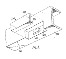
- FIG. 3 shows a still further modification to the invention where, instead of providing a cover member, such as the previously described cover member 30, which extends all along the length of the transom member and which together with the support member such as support member 12, defines an elongate compartment extending all along the transom member, simply has a small dimension recess 320 formed in a metal extrusion 322 forming the transom member.
- the recess 320 is formed adjacent the outer, lower edge 324 of the extrusion 322 and is covered with a plastics cover member 336 which is removable.
- Cover member 336 has an upward extending generally planar portion 338 and a rearwardly extending generally planar portion 340.
- a sensor device 342 similar to the previously described sensor devices such as device 20, is positioned in the compartment defined between recess 320 and cover member 336.
- Figure 5 shows in diagrammatic form the door assembly 8 of Figure 1, with its sensor device 20. Because of the internal mounting of the sensor device 20, the sensor device is located quite close to the door panel 108 and close to its median plane. As a result, the radiation pattern of radiation emitted from the diode 303, as shown by phantom lines 306 in Figure 5, has the characteristic that whilst extending some distance outwardly from the door panel so as to enable proper sensing of persons approaching the door panel, it also extends down the front surface of the metal door panel.
- the sensor device is rather clear of the door panel and the pattern 310 of radiation is less clearly directed to encompass the door panel. It has been found that by positioning the sensoring device within the transom in accordance with this invention, the proximity of the sensor device and the door panel brings about the effect of the door panel acts as an antenna for assisting in radiation of electromagnetic radiation away from the sensor device. As a consequence of this, movement of the door panel in its own plane has been found to cause minimal interference with the field of the radiation and movement of the door is not perceived readily by the detector section 304 of the sensor device.
- the door panel is positioned at a location where movement thereof is readily detectable by the sensor device.
- the positioning of the sensor device 20 within the transom member and close to the door panel allows the sensor device to be set to have a greater sensitivity without interference in operation thereof.
- the sensor device is able to direct electromagnetic radiation downwardly at an angle to the horizontal from the cavity in which it is retained and through portions of the cover member, such as cover member 30, which extend upwardly from the front rear edge of the transom member and rearwardly from such edge.
- the invention has been specifically described in relation to embodiments including a sensor device generating and detecting energy in a particular form of electromagnetic radiation, namely microwave frequency radiation, it is possible to practise the invention using sensor devices generating and detecting other forms of energy, such as sound energy or infra-red radiation.
- the sensor device may be of a kind not including an energy generator, but still responsive to energy, such as infra-red radiation, from a person approaching the device.
Landscapes
- Engineering & Computer Science (AREA)
- Civil Engineering (AREA)
- Structural Engineering (AREA)
- Mechanical Engineering (AREA)
- Power-Operated Mechanisms For Wings (AREA)
Claims (11)
Priority Applications (1)
| Application Number | Priority Date | Filing Date | Title |
|---|---|---|---|
| AT82903439T ATE36186T1 (de) | 1981-12-02 | 1982-12-01 | Querbalkenteil fuer eine tuer. |
Applications Claiming Priority (6)
| Application Number | Priority Date | Filing Date | Title |
|---|---|---|---|
| AU78158/81 | 1981-12-02 | ||
| AU78157/81A AU523382B3 (en) | 1981-12-02 | 1981-12-02 | Sliding door transom housing sensing means |
| AU78158/81A AU537963C (en) | 1981-12-02 | Transom member for sliding door | |
| AU78157/81 | 1981-12-02 | ||
| US391903 | 1982-06-25 | ||
| US06/391,903 US4809000A (en) | 1981-09-04 | 1982-06-25 | Transom member for sliding doors |
Publications (3)
| Publication Number | Publication Date |
|---|---|
| EP0107663A1 EP0107663A1 (de) | 1984-05-09 |
| EP0107663A4 EP0107663A4 (de) | 1985-09-18 |
| EP0107663B1 true EP0107663B1 (de) | 1988-08-03 |
Family
ID=27156277
Family Applications (1)
| Application Number | Title | Priority Date | Filing Date |
|---|---|---|---|
| EP19820903439 Expired EP0107663B1 (de) | 1981-12-02 | 1982-12-01 | Querbalkenteil für eine tür |
Country Status (4)
| Country | Link |
|---|---|
| EP (1) | EP0107663B1 (de) |
| DE (1) | DE3278858D1 (de) |
| GB (1) | GB2130296B (de) |
| WO (1) | WO1983001976A1 (de) |
Cited By (1)
| Publication number | Priority date | Publication date | Assignee | Title |
|---|---|---|---|---|
| EP3910145A1 (de) * | 2020-05-12 | 2021-11-17 | dormakaba Deutschland GmbH | Schiebetüranlage |
Families Citing this family (2)
| Publication number | Priority date | Publication date | Assignee | Title |
|---|---|---|---|---|
| DE8806956U1 (de) * | 1988-05-27 | 1989-09-28 | Robert Bosch Gmbh, 7000 Stuttgart | Torantrieb |
| DE4308802C5 (de) * | 1993-03-19 | 2010-12-16 | Geze Gmbh | Tür- oder Fensteranlage |
Family Cites Families (10)
| Publication number | Priority date | Publication date | Assignee | Title |
|---|---|---|---|---|
| US3039764A (en) * | 1959-01-02 | 1962-06-19 | Kawneer Co | Electric door operator |
| FR1520903A (fr) * | 1967-03-29 | 1968-04-12 | Dispositif de détection à ultra-sons | |
| US3742434A (en) * | 1971-09-30 | 1973-06-26 | Republic Industries | Automatic door-opening system using an acoustic object detection system |
| BE791601A (fr) * | 1971-11-18 | 1973-03-16 | Nordiske Kabel Traad | Moulure d'encadrement de porte ou de fenetre |
| FR2165755B1 (de) * | 1971-12-29 | 1977-01-14 | Sfim | |
| US3852592A (en) * | 1973-06-07 | 1974-12-03 | Stanley Works | Automatic door operator |
| FR2234792A5 (en) * | 1973-06-21 | 1975-01-17 | Radiotechnique Compelec | Automatic Doppler radar door control - has delay circuits with double inverter and controlling motors |
| US4009476A (en) * | 1975-06-27 | 1977-02-22 | Solfan Security Systems | Apparatus for automatically controlling door operation |
| DE2805539A1 (de) * | 1978-02-10 | 1979-08-16 | Kiekert Soehne Arn | Automatische sicherheitsschiebetuer |
| US4281481A (en) * | 1980-01-18 | 1981-08-04 | United States Gypsum Company | Fire resistant aluminum door frame assembly |
-
1982
- 1982-12-01 DE DE8282903439T patent/DE3278858D1/de not_active Expired
- 1982-12-01 EP EP19820903439 patent/EP0107663B1/de not_active Expired
- 1982-12-01 GB GB08400127A patent/GB2130296B/en not_active Expired
- 1982-12-01 WO PCT/AU1982/000203 patent/WO1983001976A1/en not_active Ceased
Cited By (1)
| Publication number | Priority date | Publication date | Assignee | Title |
|---|---|---|---|---|
| EP3910145A1 (de) * | 2020-05-12 | 2021-11-17 | dormakaba Deutschland GmbH | Schiebetüranlage |
Also Published As
| Publication number | Publication date |
|---|---|
| DE3278858D1 (en) | 1988-09-08 |
| GB8400127D0 (en) | 1984-02-08 |
| GB2130296A (en) | 1984-05-31 |
| EP0107663A1 (de) | 1984-05-09 |
| EP0107663A4 (de) | 1985-09-18 |
| WO1983001976A1 (en) | 1983-06-09 |
| GB2130296B (en) | 1985-08-07 |
Similar Documents
| Publication | Publication Date | Title |
|---|---|---|
| US4467251A (en) | Object sensing apparatus | |
| US3852592A (en) | Automatic door operator | |
| US5177900A (en) | Automatic pet door | |
| US4823010A (en) | Sliding door threshold sensor | |
| US6525659B2 (en) | Automatic sliding door system for refrigerator unit | |
| CN101855420B (zh) | 控制垂直或水平运动的门并相对于障碍物对门关闭平面加以保护的方法和装置 | |
| US4809000A (en) | Transom member for sliding doors | |
| US4569533A (en) | Van step | |
| DE69314953D1 (de) | Verfahren und vorrichtung zum auffinden und schützen von personen und objekten | |
| EP1484466A3 (de) | Verfahren und Vorrichtung zur Überwachung einer Öffnung nach einem sich in der Öffnung befindenden Objekts | |
| DE59915060D1 (de) | Automatisches Türöffnungssystem | |
| EP0107663B1 (de) | Querbalkenteil für eine tür | |
| KR100623055B1 (ko) | 방해물을 탐지하기 위한 광학 시스템 | |
| CA2398943A1 (en) | Safety interlock for mechanically actuated closure device | |
| NZ201695A (en) | Sliding door transom with concealed door opening sensor | |
| AU607699B2 (en) | Transom member for sliding doors | |
| US4157731A (en) | Protective housing for strip heaters | |
| AU776524B2 (en) | Shutter lassembly with sensor device and related sensor device assembly | |
| JPS5840625Y2 (ja) | 火災検知装置のような盤製品 | |
| CN214365725U (zh) | 一种安全的两翼旋转自动门 | |
| US5955852A (en) | Door having a door maneuvering mechanism having a slide rail with a sensor in the slide rail | |
| JPS57120875A (en) | Method for monitoring rear of vehicle | |
| JPS6460590A (en) | Step foreign-matter detector for escalator | |
| JPS6444879A (en) | Ultrasonic object detector | |
| JPH0420960Y2 (de) |
Legal Events
| Date | Code | Title | Description |
|---|---|---|---|
| PUAI | Public reference made under article 153(3) epc to a published international application that has entered the european phase |
Free format text: ORIGINAL CODE: 0009012 |
|
| 17P | Request for examination filed |
Effective date: 19840105 |
|
| AK | Designated contracting states |
Designated state(s): AT BE CH DE FR LI LU NL SE |
|
| 17Q | First examination report despatched |
Effective date: 19870211 |
|
| GRAA | (expected) grant |
Free format text: ORIGINAL CODE: 0009210 |
|
| AK | Designated contracting states |
Kind code of ref document: B1 Designated state(s): AT BE CH DE FR LI LU NL SE |
|
| PG25 | Lapsed in a contracting state [announced via postgrant information from national office to epo] |
Ref country code: AT Effective date: 19880803 |
|
| REF | Corresponds to: |
Ref document number: 36186 Country of ref document: AT Date of ref document: 19880815 Kind code of ref document: T |
|
| REF | Corresponds to: |
Ref document number: 3278858 Country of ref document: DE Date of ref document: 19880908 |
|
| ET | Fr: translation filed | ||
| PG25 | Lapsed in a contracting state [announced via postgrant information from national office to epo] |
Ref country code: LU Free format text: LAPSE BECAUSE OF NON-PAYMENT OF DUE FEES Effective date: 19881231 |
|
| PLBE | No opposition filed within time limit |
Free format text: ORIGINAL CODE: 0009261 |
|
| STAA | Information on the status of an ep patent application or granted ep patent |
Free format text: STATUS: NO OPPOSITION FILED WITHIN TIME LIMIT |
|
| 26N | No opposition filed | ||
| PGFP | Annual fee paid to national office [announced via postgrant information from national office to epo] |
Ref country code: NL Payment date: 19911231 Year of fee payment: 10 |
|
| PGFP | Annual fee paid to national office [announced via postgrant information from national office to epo] |
Ref country code: FR Payment date: 19920601 Year of fee payment: 10 |
|
| PGFP | Annual fee paid to national office [announced via postgrant information from national office to epo] |
Ref country code: SE Payment date: 19920605 Year of fee payment: 10 |
|
| PGFP | Annual fee paid to national office [announced via postgrant information from national office to epo] |
Ref country code: CH Payment date: 19920619 Year of fee payment: 10 |
|
| PGFP | Annual fee paid to national office [announced via postgrant information from national office to epo] |
Ref country code: DE Payment date: 19920629 Year of fee payment: 10 |
|
| PGFP | Annual fee paid to national office [announced via postgrant information from national office to epo] |
Ref country code: BE Payment date: 19920706 Year of fee payment: 10 |
|
| PG25 | Lapsed in a contracting state [announced via postgrant information from national office to epo] |
Ref country code: SE Effective date: 19921202 |
|
| PG25 | Lapsed in a contracting state [announced via postgrant information from national office to epo] |
Ref country code: LI Effective date: 19921231 Ref country code: CH Effective date: 19921231 Ref country code: BE Effective date: 19921231 |
|
| BERE | Be: lapsed |
Owner name: SECTON PTY.LTD Effective date: 19921231 |
|
| PG25 | Lapsed in a contracting state [announced via postgrant information from national office to epo] |
Ref country code: NL Effective date: 19930701 |
|
| NLV4 | Nl: lapsed or anulled due to non-payment of the annual fee | ||
| PG25 | Lapsed in a contracting state [announced via postgrant information from national office to epo] |
Ref country code: FR Effective date: 19930831 |
|
| REG | Reference to a national code |
Ref country code: CH Ref legal event code: PL |
|
| PG25 | Lapsed in a contracting state [announced via postgrant information from national office to epo] |
Ref country code: DE Effective date: 19930901 |
|
| REG | Reference to a national code |
Ref country code: FR Ref legal event code: ST |
|
| EUG | Se: european patent has lapsed |
Ref document number: 82903439.6 Effective date: 19930709 |