EP0107837A1 - Système d'extinction d'incendie - Google Patents
Système d'extinction d'incendie Download PDFInfo
- Publication number
- EP0107837A1 EP0107837A1 EP83110318A EP83110318A EP0107837A1 EP 0107837 A1 EP0107837 A1 EP 0107837A1 EP 83110318 A EP83110318 A EP 83110318A EP 83110318 A EP83110318 A EP 83110318A EP 0107837 A1 EP0107837 A1 EP 0107837A1
- Authority
- EP
- European Patent Office
- Prior art keywords
- tank
- fire extinguishing
- medium
- expellant
- pressure
- Prior art date
- Legal status (The legal status is an assumption and is not a legal conclusion. Google has not performed a legal analysis and makes no representation as to the accuracy of the status listed.)
- Granted
Links
- 239000000463 material Substances 0.000 claims abstract description 32
- 239000007788 liquid Substances 0.000 claims abstract description 9
- 238000001514 detection method Methods 0.000 claims abstract description 4
- IJGRMHOSHXDMSA-UHFFFAOYSA-N Atomic nitrogen Chemical compound N#N IJGRMHOSHXDMSA-UHFFFAOYSA-N 0.000 claims description 10
- 238000004891 communication Methods 0.000 claims description 7
- 150000008282 halocarbons Chemical class 0.000 claims description 5
- 230000000977 initiatory effect Effects 0.000 claims description 5
- 238000000034 method Methods 0.000 claims description 5
- 229910052757 nitrogen Inorganic materials 0.000 claims description 5
- 238000011144 upstream manufacturing Methods 0.000 claims 1
- 230000000694 effects Effects 0.000 abstract description 2
- 230000007423 decrease Effects 0.000 description 4
- 230000008878 coupling Effects 0.000 description 2
- 238000010168 coupling process Methods 0.000 description 2
- 238000005859 coupling reaction Methods 0.000 description 2
- 238000012423 maintenance Methods 0.000 description 2
- RJCQBQGAPKAMLL-UHFFFAOYSA-N bromotrifluoromethane Chemical compound FC(F)(F)Br RJCQBQGAPKAMLL-UHFFFAOYSA-N 0.000 description 1
- 238000002485 combustion reaction Methods 0.000 description 1
- 239000007789 gas Substances 0.000 description 1
- 238000009434 installation Methods 0.000 description 1
- 238000012986 modification Methods 0.000 description 1
- 230000004048 modification Effects 0.000 description 1
- 230000001960 triggered effect Effects 0.000 description 1
Images

Classifications
-
- A—HUMAN NECESSITIES
- A62—LIFE-SAVING; FIRE-FIGHTING
- A62C—FIRE-FIGHTING
- A62C99/00—Subject matter not provided for in other groups of this subclass
- A62C99/0009—Methods of extinguishing or preventing the spread of fire by cooling down or suffocating the flames
- A62C99/0018—Methods of extinguishing or preventing the spread of fire by cooling down or suffocating the flames using gases or vapours that do not support combustion, e.g. steam, carbon dioxide
-
- A—HUMAN NECESSITIES
- A62—LIFE-SAVING; FIRE-FIGHTING
- A62C—FIRE-FIGHTING
- A62C3/00—Fire prevention, containment or extinguishing specially adapted for particular objects or places
- A62C3/16—Fire prevention, containment or extinguishing specially adapted for particular objects or places in electrical installations, e.g. cableways
-
- A—HUMAN NECESSITIES
- A62—LIFE-SAVING; FIRE-FIGHTING
- A62C—FIRE-FIGHTING
- A62C35/00—Permanently-installed equipment
- A62C35/58—Pipe-line systems
- A62C35/62—Pipe-line systems dry, i.e. empty of extinguishing material when not in use
-
- A—HUMAN NECESSITIES
- A62—LIFE-SAVING; FIRE-FIGHTING
- A62C—FIRE-FIGHTING
- A62C37/00—Control of fire-fighting equipment
Definitions
- the present invention relates to a system for the extinguishment of fires with a fire extinguishing medium.
- This invention is achieved by providing a system where the fire extinguishing medium partially fills the tank and where an expellant material under pressure occupies the remaining part of the tank, the expellant material defining a pressure cushion acting on the fire extinguishing medium; a delivery line for carrying the medium from the tank to a hazard is equipped with a normally closed main valve which is operable to deliver the fire extinguishing medium to the hazard; the system also includes a reserve of expellant containing means in conduit communication with the pressure cushion inside the tank; actuator means operate the valve and initiate the sequential operation of.the expellant containing means for the delivering of additional expellant material to the tank to maintain a given pressure in the tank and to effect a quick and total evacuation of the medium from the tank to the hazard.
- the medium is a liquid halogenated hydrocarbon and the expellant material is nitrogen.
- the present invention is also concerned with a method of extinguishing fires which comprises the steps of:
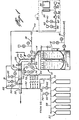
- a large storage tank 10 which is partially filled with a liquid fire extinguishing medium 12 above which is a cushion of expellant material 14 under pressure.
- a preferred medium is a liquid halogenated hydrocarbon, such as the one sold under the trade mark HALON 1301, while a preferred expellant material is nitrogen.
- a fill line 16 is shown at the bottom of the tank for storing the medium in the tank and includes a series of commonly known and used components such as valves, rupture disks, coupling adaptors for the proper filling operation of the tank.
- an equalizing line 18 connected between the tank and the source of medium 12 and equipped with similar known components, J such as valves,rupture disks, coupling adaptors, for use during the conventional filling operation of a medium containing tank.
- a delivery line generally denoted 20, includes a first portion 22 which extends inside the storage tank with one end 23 terminating adjacent the bottom thereof.
- a second portion 24 of the delivery line comprises a normally closed remotely operated main valve 26, preferably of the butterfly type, and a second valve 28 which is normally open and is used whenever maintenance is required on the main valve 26.
- the delivery line portion 24 further includes a rupture disk 30 which is located downstream of the main valve 26 and which is used for detecting any leaks of the fire extinguishing medium which may accidently pass by valve 26 when closed.
- An arrangement of pressure detecting device 31, manometer 33 and valves is provided between valve 26 and disk 30 to indicate to a controlling station,generally designated as 34, an increase or decrease in pressure in the delivery line.
- the remaining portion 32 of the delivery line is connected to a nozzle distributing system (not shown) which is mounted in the environment to be protected.
- the actuation, i.e. opening, of the butterfly valve 26 is carried out upon receiving a signal transmitted from the controlling station which, in turn, operates upon detection of a fire Hazard in the room where the distributing system is located.
- the station includes a control panel 36, a pneumatic actuator 38, a manometer 40 and a pressure detecting switch 42.
- the controlling station 34 also includes a series of valves 46, 47, 48, 49, a pressure regulator 50 and a pressure detecting instrument 51.
- the signal transmitted on line 44 from the controlling station 34 is also transmitted on a second line 52 associated with a plurality of groups of containers, five groups having been shown in figure 2 as 53, 54, 55, 56, 57, each group including a series of cylinders (six being shown).
- the containers of each group are serially connected to a common delivery line 58, 59, 60, 61, 62, respectively, each line being in conduit communication with the upper part of the tank 10 through a common conduit 64 and a valve 66.
- a pressure detecting device 68 and a manometer 70 mounted to the upper part of the storage tank are mounted to the upper part of the storage tank are a pressure detecting device 68 and a manometer 70, in communication with the tank through respective valves 72 and 74, to detect and measure the pressure therein.
- the pressure detecting device 68 will indicate a variation in pressure inside the tank and will transmit a signal to the controlling station.
- An increase of pressure inside the tank will indicate an increase of temperature which will create expansion of the medium inside the tank and/or a leak of the expellant material.
- ⁇ decrease in pressure will indicate a leak of the expellant material or of the fire extinguishing medium and/or a temperature decrease.
- the first group 53 includes a diaphragm operated valve . 75 in the delivery line 58, a pressure detecting device 76 connected to line 58 through a valve 80, a manometer 78 also connected to line 58 through a valve 82. Similar component arrangements are provided for each of the other lines 54, 55, 56 and 57 and have been given letter references to distinguish them from one another.
- solenoid valves 84, 84 A, 84 B, 84 C and 84 D which, when operated, actuate respective valves 75, 75 A, 75 B, 75 C and 75 D.
- Solenoid valve 84 is electrically connected to a timer device 86.
- the other solenoid valves are connected to the timer-through respective pressure switches 76, 76 A, 76 B, 76 C and 76 D.
- Connected to the timer are two normally opened contacts 42 and 88 which close in response to the a pressure increase in lines 44 and 20 respectively.
- Timer 86 also includes a pair of contacts 92 (normally closed) and 94 (normally open).
- tank 10 contains a quantity of fire extinguishing medium in liquid state which is pressurized by the cushion of expellant material 14.
- the butterfly valve 26 is normally closed while the rupture disk 30 is in place; valve 28 is open.
- the opening of butterfly valve 26 is actuated by a pneumatic or electric signal received from the controlling station 34.
- the number of groups of cylinders of expellant material will correspond to that which is required to assist the cushion pf expellant material inside the tank to expel quickly and totally the fire extinguishing medium to the hazard in a desired time interval.
- the signal received from the controlling station opens the butterfly valve 26.
- This signal is also sent to the solenoid valves 84, 84 A, 84 B, 84 C and 84 D; however, these valves will actuate their corresponding valves 75, 75 A, 75 B, 75 C and 75 D only when electrically energized.
- Solenoid valve 84 will be actuated when timer 86 is energized: this is accomplished when contacts 42 and 88 are closed.
- Contact 42 is closed when the controlling station sends a signal on line 44 whereas contact 88 is closed when the pressure inside conduit 20 between valves 26 and disc 30 is sufficiently high and detected by switch 88.
- Timer 86 once energized, will cause and maintain closure of contact 94 for a set delay resulting in actuation of valve 84 and valve 75. This will cause the first group 53.of six cylinders to direct additional expellant material to the tank through conduit 64, the latter acting as an orifice and reducing the pressure of expellant material from a high value inside the containers to a sufficient pressure to expel the medium from the tank.
- the contact of pressure detecting device 76 closes to actuate the solenpid valve 84 A of the succeeding group of six containers, which valve opens an associated valve 75 A to put the expellant material of that group in communication with line 64; and so on, until the last group of containers is emptied.
- This sequential operation enables to maintain a constant pressure inside the tank during the delivery time.
- the pressure detecting device 76 D of the last or fifth group transmits a signal to the controlling station 34 to indicate total evacuation of the expellant material.
- the set delay on.timer 86 corresponds to the time required for total evacuation of the medium and ensures this continuous electric supply even if contacts 42 and 88 should open:
- the gas under pressure in the containers could be air.
- air would react with the halogenated hydrocarbon and it would be preferable that the pressure cushion inside the tank be nitrogen while the expellant material outside the tank would be air or any other material under pressure.
- the reserve of expellant material it is possible to envisage the reserve of expellant material as being a large spherical container. It is therefore wished to have it understood that this invention should not be limited in interpretation except by the terms of the following claims.
Landscapes
- Health & Medical Sciences (AREA)
- Public Health (AREA)
- Business, Economics & Management (AREA)
- Emergency Management (AREA)
- Fire-Extinguishing By Fire Departments, And Fire-Extinguishing Equipment And Control Thereof (AREA)
- Fire Alarms (AREA)
- Cereal-Derived Products (AREA)
- Fire-Extinguishing Compositions (AREA)
- Chemical And Physical Treatments For Wood And The Like (AREA)
Priority Applications (1)
| Application Number | Priority Date | Filing Date | Title |
|---|---|---|---|
| AT83110318T ATE24278T1 (de) | 1982-11-01 | 1983-10-15 | Feuerloeschsystem. |
Applications Claiming Priority (2)
| Application Number | Priority Date | Filing Date | Title |
|---|---|---|---|
| CA414603 | 1982-11-01 | ||
| CA000414603A CA1152857A (fr) | 1982-11-01 | 1982-11-01 | Systeme extincteur |
Publications (2)
| Publication Number | Publication Date |
|---|---|
| EP0107837A1 true EP0107837A1 (fr) | 1984-05-09 |
| EP0107837B1 EP0107837B1 (fr) | 1986-12-17 |
Family
ID=4123860
Family Applications (1)
| Application Number | Title | Priority Date | Filing Date |
|---|---|---|---|
| EP83110318A Expired EP0107837B1 (fr) | 1982-11-01 | 1983-10-15 | Système d'extinction d'incendie |
Country Status (16)
| Country | Link |
|---|---|
| US (1) | US4520871A (fr) |
| EP (1) | EP0107837B1 (fr) |
| AT (1) | ATE24278T1 (fr) |
| AU (1) | AU553816B2 (fr) |
| CA (1) | CA1152857A (fr) |
| DE (1) | DE3368388D1 (fr) |
| DK (1) | DK488483A (fr) |
| ES (1) | ES8406210A1 (fr) |
| GR (1) | GR79641B (fr) |
| MW (1) | MW3783A1 (fr) |
| NO (1) | NO833901L (fr) |
| NZ (1) | NZ205781A (fr) |
| PT (1) | PT77473B (fr) |
| ZA (1) | ZA837285B (fr) |
| ZM (1) | ZM7083A1 (fr) |
| ZW (1) | ZW21983A1 (fr) |
Cited By (3)
| Publication number | Priority date | Publication date | Assignee | Title |
|---|---|---|---|---|
| WO1993010859A1 (fr) * | 1991-11-26 | 1993-06-10 | Sundholm Goeran | Materiel anti-incendies |
| EP0511230A4 (fr) * | 1990-01-08 | 1994-04-13 | Pyrozone Pty. Ltd. | |
| WO1994008659A1 (fr) * | 1992-10-20 | 1994-04-28 | Sundholm Goeran | Procede et installation de lutte contre le feu |
Families Citing this family (17)
| Publication number | Priority date | Publication date | Assignee | Title |
|---|---|---|---|---|
| FR2583293B1 (fr) * | 1985-06-14 | 1988-08-26 | Lejosne Alain | Dispositif pour combattre les incendies de forets |
| AT386527B (de) * | 1986-02-20 | 1988-09-12 | Elin Union Ag | Einrichtung zum loeschen eines brandes |
| US5027905A (en) * | 1989-07-26 | 1991-07-02 | Cousineau Ronald L | Fire sprinkler control apparatus |
| FI935033A0 (fi) * | 1993-11-12 | 1993-11-12 | Goeran Sundholm | Foerfarande och installation foer eldslaeckning |
| KR100353177B1 (ko) * | 1994-04-14 | 2002-12-26 | 마리오프 코퍼레이션 오이 | 액상-기상연무를방출하는소화장치 |
| MY132201A (en) * | 1995-02-03 | 2007-09-28 | Great Lakes Chemical Corp | Method and system for delivering a fire suppression composition to a hazard |
| FI102728B1 (fi) * | 1997-09-15 | 1999-02-15 | Goeran Sundholm | Palonsammutuslaitteisto |
| US6109359A (en) * | 1999-03-23 | 2000-08-29 | Ballard; Paul Corwin | Compressed air foam system |
| US6896067B2 (en) * | 2002-09-23 | 2005-05-24 | James Bowyer | Method and apparatus for distributing fire suppressant |
| US7117950B2 (en) * | 2004-06-07 | 2006-10-10 | Mclane Jr Samuel D | Fire suppression system |
| US7416030B2 (en) * | 2005-07-21 | 2008-08-26 | Kidde Fenwal, Inc. | Adjustable time delay for fire suppression system |
| WO2008052390A1 (fr) * | 2006-11-02 | 2008-05-08 | Weishe Zhang | Dispositif de stockage et de distribution d'agent d'extinction d'idendie |
| US7896093B2 (en) * | 2007-05-25 | 2011-03-01 | Greg Chavez | Localized fire suppression |
| ES1073690Y (es) * | 2010-04-27 | 2011-04-25 | L P G Tecn En Extincion De Incendios S L | Disposicion de botellas contenedoras de gas extintor para instalaciones de extincion de incendios |
| GB2486267B (en) | 2010-12-09 | 2014-12-17 | Kidde Tech Inc | Combined fire extinguishing system |
| WO2013028152A1 (fr) * | 2011-08-19 | 2013-02-28 | Utc Fire & Security Corporation | Système et procédé de conditionnement et de distribution d'un agent liquide d'extinction d'incendie |
| CN107080911A (zh) * | 2017-06-08 | 2017-08-22 | 太仓苏安消防设备有限公司 | 一种七氟丙烷灭火系统 |
Citations (6)
| Publication number | Priority date | Publication date | Assignee | Title |
|---|---|---|---|---|
| FR816542A (fr) * | 1936-11-12 | 1937-08-10 | Installation d'extinction de feu à action automatique et commandée à distance pour locaux à danger d'incendie, véhicules automobiles, avions, bateaux, etc. | |
| US2353117A (en) * | 1942-07-13 | 1944-07-04 | Automatic Sprinkler Co | Deluge or preaction pressure tank sprinkler system with secondary supply |
| DE1028886B (de) * | 1952-04-22 | 1958-04-24 | Minimax Ag | Vorrichtung zur UEberwachung der Dichtheit von Kohlensaeureflaschen, insbesondere fuer Feuerloeschzwecke, und Schaltung fuer eine von dieser Vorrichtung zu betaetigende Alarmeinrichtung |
| DE2456207B1 (de) * | 1974-11-28 | 1976-03-04 | Preussag Ag Minimax | Feuerloeschanlage |
| GB2056624A (en) * | 1979-08-10 | 1981-03-18 | Mcculloch A | Valve |
| AU516808B2 (en) * | 1977-11-18 | 1981-06-25 | Security Patrols Co., Ltd | Fire extinguishing system |
Family Cites Families (8)
| Publication number | Priority date | Publication date | Assignee | Title |
|---|---|---|---|---|
| US868218A (en) * | 1893-10-16 | 1907-10-15 | Osborne Steam Engineering Company | Apparatus for the use of carbon dioxid for the extinguishment of fires. |
| US2290358A (en) * | 1940-08-21 | 1942-07-21 | Automatic Sprinkler Company | Sprinkler system with pressure tank water supply |
| US2933139A (en) * | 1958-04-04 | 1960-04-19 | O'rear Harrel William | Fire extinguisher systems |
| US3052304A (en) * | 1959-04-29 | 1962-09-04 | Chemetron Corp | Fire extinguishing system |
| US3497012A (en) * | 1967-05-18 | 1970-02-24 | Chemetron Corp | Method and apparatus for extinguishing fires |
| US3486562A (en) * | 1968-03-08 | 1969-12-30 | David K Goodloe | Fire prevention,detection and extinguishing system |
| US4069873A (en) * | 1976-04-06 | 1978-01-24 | Mcclure William F | Apparatus for fire extinguishing system for floating-roof tanks |
| US4183409A (en) * | 1976-06-11 | 1980-01-15 | Security Patrols Co., Ltd. | Automatic fire-extinguishing system |
-
1982
- 1982-11-01 CA CA000414603A patent/CA1152857A/fr not_active Expired
- 1982-11-05 US US06/439,546 patent/US4520871A/en not_active Expired - Fee Related
-
1983
- 1983-09-20 AU AU19307/83A patent/AU553816B2/en not_active Ceased
- 1983-09-28 NZ NZ205781A patent/NZ205781A/en unknown
- 1983-09-29 ZA ZA837285A patent/ZA837285B/xx unknown
- 1983-10-05 MW MW37/83A patent/MW3783A1/xx unknown
- 1983-10-07 PT PT77473A patent/PT77473B/pt unknown
- 1983-10-10 ZM ZM70/83A patent/ZM7083A1/xx unknown
- 1983-10-12 ZW ZW219/83A patent/ZW21983A1/xx unknown
- 1983-10-15 EP EP83110318A patent/EP0107837B1/fr not_active Expired
- 1983-10-15 DE DE8383110318T patent/DE3368388D1/de not_active Expired
- 1983-10-15 AT AT83110318T patent/ATE24278T1/de active
- 1983-10-25 DK DK488483A patent/DK488483A/da not_active Application Discontinuation
- 1983-10-26 ES ES526762A patent/ES8406210A1/es not_active Expired
- 1983-10-26 NO NO833901A patent/NO833901L/no unknown
- 1983-10-31 GR GR72824A patent/GR79641B/el unknown
Patent Citations (6)
| Publication number | Priority date | Publication date | Assignee | Title |
|---|---|---|---|---|
| FR816542A (fr) * | 1936-11-12 | 1937-08-10 | Installation d'extinction de feu à action automatique et commandée à distance pour locaux à danger d'incendie, véhicules automobiles, avions, bateaux, etc. | |
| US2353117A (en) * | 1942-07-13 | 1944-07-04 | Automatic Sprinkler Co | Deluge or preaction pressure tank sprinkler system with secondary supply |
| DE1028886B (de) * | 1952-04-22 | 1958-04-24 | Minimax Ag | Vorrichtung zur UEberwachung der Dichtheit von Kohlensaeureflaschen, insbesondere fuer Feuerloeschzwecke, und Schaltung fuer eine von dieser Vorrichtung zu betaetigende Alarmeinrichtung |
| DE2456207B1 (de) * | 1974-11-28 | 1976-03-04 | Preussag Ag Minimax | Feuerloeschanlage |
| AU516808B2 (en) * | 1977-11-18 | 1981-06-25 | Security Patrols Co., Ltd | Fire extinguishing system |
| GB2056624A (en) * | 1979-08-10 | 1981-03-18 | Mcculloch A | Valve |
Cited By (6)
| Publication number | Priority date | Publication date | Assignee | Title |
|---|---|---|---|---|
| EP0511230A4 (fr) * | 1990-01-08 | 1994-04-13 | Pyrozone Pty. Ltd. | |
| WO1993010859A1 (fr) * | 1991-11-26 | 1993-06-10 | Sundholm Goeran | Materiel anti-incendies |
| US5632337A (en) * | 1991-11-26 | 1997-05-27 | Sundholm; Goeran | Fire-fighting equipment |
| KR100258012B1 (ko) * | 1991-11-26 | 2000-06-01 | 괴란 순트홀름 | 소화장치 |
| WO1994008659A1 (fr) * | 1992-10-20 | 1994-04-28 | Sundholm Goeran | Procede et installation de lutte contre le feu |
| US5676210A (en) * | 1992-10-20 | 1997-10-14 | Sundholm; Goeran | Method and installation for fighting fire |
Also Published As
| Publication number | Publication date |
|---|---|
| GR79641B (fr) | 1984-10-31 |
| ZW21983A1 (en) | 1984-05-30 |
| US4520871A (en) | 1985-06-04 |
| CA1152857A (fr) | 1983-08-30 |
| DK488483D0 (da) | 1983-10-25 |
| NZ205781A (en) | 1987-04-30 |
| DE3368388D1 (en) | 1987-01-29 |
| ES526762A0 (es) | 1984-08-01 |
| PT77473A (en) | 1983-11-01 |
| EP0107837B1 (fr) | 1986-12-17 |
| AU553816B2 (en) | 1986-07-31 |
| MW3783A1 (en) | 1985-03-13 |
| ATE24278T1 (de) | 1987-01-15 |
| AU1930783A (en) | 1984-05-10 |
| ES8406210A1 (es) | 1984-08-01 |
| DK488483A (da) | 1984-05-02 |
| ZA837285B (en) | 1984-06-27 |
| ZM7083A1 (en) | 1984-06-21 |
| PT77473B (en) | 1986-02-14 |
| NO833901L (no) | 1984-05-02 |
Similar Documents
| Publication | Publication Date | Title |
|---|---|---|
| US4520871A (en) | Fire extinguishing system | |
| CA2935991C (fr) | Systeme d'extinction d'incendie dans un aeronef equipe d'une soupape de bouteille adressable | |
| GB1399749A (en) | Fire extinguishers and fire extinguishing systems | |
| US3800878A (en) | Release mechanism for pressurized vessels | |
| US20110308823A1 (en) | Programmable controller for a fire prevention system | |
| GB2190286A (en) | Fire-extinguishing installation for freight compartments of transport means | |
| EP2595709A1 (fr) | Procédés et appareil pour suppression passive, non-électrique, d'un feu en deux étapes | |
| US2933139A (en) | Fire extinguisher systems | |
| US2482778A (en) | Fluid pressure medium dispensing system | |
| KR20020075858A (ko) | 화재를 진화하기 위한 장치 | |
| GB1382448A (en) | Dewar filling purging and draining systems | |
| US5027905A (en) | Fire sprinkler control apparatus | |
| GB1342820A (en) | Automatic fire extinguishing systems | |
| GB1411470A (en) | Sprinkler installation | |
| US2544016A (en) | Fire extinguishing system | |
| US4183409A (en) | Automatic fire-extinguishing system | |
| US11691039B2 (en) | Aircraft comprising a propulsion assembly and a fire-fighting system for the propulsion assembly | |
| US3160212A (en) | Remotely actuated magazine sprinkler valve | |
| US2724444A (en) | Wet pipe pressure tank sprinkler system | |
| JP3353213B2 (ja) | コンテナの消火装置 | |
| US11766579B2 (en) | Simultaneously discharging fire extinguisher | |
| US2608371A (en) | Tare-setting control mechanism for filling containers | |
| JPH0336373Y2 (fr) | ||
| US3075543A (en) | Float actuated vent and replenishing valves for a liquid container | |
| US4541804A (en) | Training interface device for dispensing stores |
Legal Events
| Date | Code | Title | Description |
|---|---|---|---|
| PUAI | Public reference made under article 153(3) epc to a published international application that has entered the european phase |
Free format text: ORIGINAL CODE: 0009012 |
|
| AK | Designated contracting states |
Designated state(s): AT BE CH DE FR GB IT LI LU NL SE |
|
| 17P | Request for examination filed |
Effective date: 19840808 |
|
| GRAA | (expected) grant |
Free format text: ORIGINAL CODE: 0009210 |
|
| AK | Designated contracting states |
Kind code of ref document: B1 Designated state(s): AT BE CH DE FR GB IT LI LU NL SE |
|
| PG25 | Lapsed in a contracting state [announced via postgrant information from national office to epo] |
Ref country code: LI Effective date: 19861217 Ref country code: IT Free format text: LAPSE BECAUSE OF FAILURE TO SUBMIT A TRANSLATION OF THE DESCRIPTION OR TO PAY THE FEE WITHIN THE PRESCRIBED TIME-LIMIT;WARNING: LAPSES OF ITALIAN PATENTS WITH EFFECTIVE DATE BEFORE 2007 MAY HAVE OCCURRED AT ANY TIME BEFORE 2007. THE CORRECT EFFECTIVE DATE MAY BE DIFFERENT FROM THE ONE RECORDED. Effective date: 19861217 Ref country code: CH Effective date: 19861217 Ref country code: AT Effective date: 19861217 |
|
| REF | Corresponds to: |
Ref document number: 24278 Country of ref document: AT Date of ref document: 19870115 Kind code of ref document: T |
|
| PG25 | Lapsed in a contracting state [announced via postgrant information from national office to epo] |
Ref country code: SE Effective date: 19861231 |
|
| REF | Corresponds to: |
Ref document number: 3368388 Country of ref document: DE Date of ref document: 19870129 |
|
| REG | Reference to a national code |
Ref country code: CH Ref legal event code: PL |
|
| ET | Fr: translation filed | ||
| PLBE | No opposition filed within time limit |
Free format text: ORIGINAL CODE: 0009261 |
|
| STAA | Information on the status of an ep patent application or granted ep patent |
Free format text: STATUS: NO OPPOSITION FILED WITHIN TIME LIMIT |
|
| PG25 | Lapsed in a contracting state [announced via postgrant information from national office to epo] |
Ref country code: LU Free format text: LAPSE BECAUSE OF NON-PAYMENT OF DUE FEES Effective date: 19871031 |
|
| PGFP | Annual fee paid to national office [announced via postgrant information from national office to epo] |
Ref country code: NL Payment date: 19871031 Year of fee payment: 5 |
|
| 26N | No opposition filed | ||
| PG25 | Lapsed in a contracting state [announced via postgrant information from national office to epo] |
Ref country code: GB Effective date: 19891015 |
|
| PG25 | Lapsed in a contracting state [announced via postgrant information from national office to epo] |
Ref country code: BE Effective date: 19891031 |
|
| BERE | Be: lapsed |
Owner name: WORMALD FIRE SYSTEMS INC. Effective date: 19891031 |
|
| PG25 | Lapsed in a contracting state [announced via postgrant information from national office to epo] |
Ref country code: NL Effective date: 19900501 |
|
| GBPC | Gb: european patent ceased through non-payment of renewal fee | ||
| NLV4 | Nl: lapsed or anulled due to non-payment of the annual fee | ||
| PG25 | Lapsed in a contracting state [announced via postgrant information from national office to epo] |
Ref country code: FR Effective date: 19900629 |
|
| PG25 | Lapsed in a contracting state [announced via postgrant information from national office to epo] |
Ref country code: DE Effective date: 19900703 |
|
| REG | Reference to a national code |
Ref country code: FR Ref legal event code: ST |