EP0108112B1 - Cryosurgical apparatus, especially for the cryosurgery of deeply lying lesions - Google Patents
Cryosurgical apparatus, especially for the cryosurgery of deeply lying lesions Download PDFInfo
- Publication number
- EP0108112B1 EP0108112B1 EP83901592A EP83901592A EP0108112B1 EP 0108112 B1 EP0108112 B1 EP 0108112B1 EP 83901592 A EP83901592 A EP 83901592A EP 83901592 A EP83901592 A EP 83901592A EP 0108112 B1 EP0108112 B1 EP 0108112B1
- Authority
- EP
- European Patent Office
- Prior art keywords
- cryotip
- shaft portion
- accordance
- cryosurgical apparatus
- cavity
- Prior art date
- Legal status (The legal status is an assumption and is not a legal conclusion. Google has not performed a legal analysis and makes no representation as to the accuracy of the status listed.)
- Expired
Links
- 238000002681 cryosurgery Methods 0.000 title abstract description 31
- 230000003902 lesion Effects 0.000 title abstract description 6
- IJGRMHOSHXDMSA-UHFFFAOYSA-N Atomic nitrogen Chemical compound N#N IJGRMHOSHXDMSA-UHFFFAOYSA-N 0.000 claims abstract description 34
- 238000000034 method Methods 0.000 claims abstract description 30
- 239000007788 liquid Substances 0.000 claims abstract description 25
- 238000012544 monitoring process Methods 0.000 claims abstract description 17
- 229910052757 nitrogen Inorganic materials 0.000 claims abstract description 17
- 229910052751 metal Inorganic materials 0.000 claims abstract description 15
- 239000002184 metal Substances 0.000 claims abstract description 15
- 238000002591 computed tomography Methods 0.000 claims abstract description 13
- 229910052756 noble gas Inorganic materials 0.000 claims abstract description 11
- 229910052724 xenon Inorganic materials 0.000 claims abstract description 4
- FHNFHKCVQCLJFQ-UHFFFAOYSA-N xenon atom Chemical compound [Xe] FHNFHKCVQCLJFQ-UHFFFAOYSA-N 0.000 claims abstract description 4
- 238000010438 heat treatment Methods 0.000 claims description 29
- 238000007710 freezing Methods 0.000 claims description 15
- 230000008014 freezing Effects 0.000 claims description 15
- 239000000463 material Substances 0.000 claims description 13
- 239000007789 gas Substances 0.000 claims description 12
- 239000012530 fluid Substances 0.000 claims description 11
- 229910052782 aluminium Inorganic materials 0.000 claims description 10
- XAGFODPZIPBFFR-UHFFFAOYSA-N aluminium Chemical compound [Al] XAGFODPZIPBFFR-UHFFFAOYSA-N 0.000 claims description 10
- 239000000126 substance Substances 0.000 claims description 10
- 239000004411 aluminium Substances 0.000 claims description 9
- 230000003287 optical effect Effects 0.000 claims description 9
- 230000008569 process Effects 0.000 claims description 7
- 238000011161 development Methods 0.000 claims description 6
- 229910000510 noble metal Inorganic materials 0.000 claims description 6
- OKTJSMMVPCPJKN-UHFFFAOYSA-N Carbon Chemical compound [C] OKTJSMMVPCPJKN-UHFFFAOYSA-N 0.000 claims description 4
- 239000002826 coolant Substances 0.000 claims description 4
- 239000000203 mixture Substances 0.000 claims description 4
- 229910052790 beryllium Inorganic materials 0.000 claims description 3
- 238000009434 installation Methods 0.000 claims description 3
- 238000007747 plating Methods 0.000 claims description 3
- VYZAMTAEIAYCRO-UHFFFAOYSA-N Chromium Chemical compound [Cr] VYZAMTAEIAYCRO-UHFFFAOYSA-N 0.000 claims description 2
- RYGMFSIKBFXOCR-UHFFFAOYSA-N Copper Chemical compound [Cu] RYGMFSIKBFXOCR-UHFFFAOYSA-N 0.000 claims description 2
- 239000000956 alloy Substances 0.000 claims description 2
- 229910045601 alloy Inorganic materials 0.000 claims description 2
- 239000011651 chromium Substances 0.000 claims description 2
- 229910052804 chromium Inorganic materials 0.000 claims description 2
- 239000010949 copper Substances 0.000 claims description 2
- 229910052802 copper Inorganic materials 0.000 claims description 2
- 239000000835 fiber Substances 0.000 claims description 2
- 229910052734 helium Inorganic materials 0.000 claims description 2
- 239000001307 helium Substances 0.000 claims description 2
- SWQJXJOGLNCZEY-UHFFFAOYSA-N helium atom Chemical compound [He] SWQJXJOGLNCZEY-UHFFFAOYSA-N 0.000 claims description 2
- 229910052744 lithium Inorganic materials 0.000 claims description 2
- 229910052749 magnesium Inorganic materials 0.000 claims description 2
- 238000005192 partition Methods 0.000 claims description 2
- 229910052743 krypton Inorganic materials 0.000 claims 1
- DNNSSWSSYDEUBZ-UHFFFAOYSA-N krypton atom Chemical compound [Kr] DNNSSWSSYDEUBZ-UHFFFAOYSA-N 0.000 claims 1
- 229920002994 synthetic fiber Polymers 0.000 claims 1
- 229920003023 plastic Polymers 0.000 abstract description 9
- 239000004033 plastic Substances 0.000 abstract description 8
- 206010028980 Neoplasm Diseases 0.000 abstract description 7
- 238000000315 cryotherapy Methods 0.000 abstract description 3
- AANMVENRNJYEMK-UHFFFAOYSA-N 4-propan-2-ylcyclohex-2-en-1-one Chemical compound CC(C)C1CCC(=O)C=C1 AANMVENRNJYEMK-UHFFFAOYSA-N 0.000 abstract description 2
- 150000002739 metals Chemical class 0.000 abstract 1
- 210000001519 tissue Anatomy 0.000 description 39
- 238000001816 cooling Methods 0.000 description 17
- 230000008859 change Effects 0.000 description 9
- 238000012546 transfer Methods 0.000 description 9
- 210000004027 cell Anatomy 0.000 description 7
- XLYOFNOQVPJJNP-UHFFFAOYSA-N water Substances O XLYOFNOQVPJJNP-UHFFFAOYSA-N 0.000 description 7
- 230000006378 damage Effects 0.000 description 6
- 238000013461 design Methods 0.000 description 5
- 238000003384 imaging method Methods 0.000 description 5
- 238000005259 measurement Methods 0.000 description 5
- 238000001356 surgical procedure Methods 0.000 description 5
- 238000009835 boiling Methods 0.000 description 4
- PCHJSUWPFVWCPO-UHFFFAOYSA-N gold Chemical compound [Au] PCHJSUWPFVWCPO-UHFFFAOYSA-N 0.000 description 4
- 239000010931 gold Substances 0.000 description 4
- 229910052737 gold Inorganic materials 0.000 description 4
- 239000000523 sample Substances 0.000 description 4
- 239000000853 adhesive Substances 0.000 description 3
- 230000001070 adhesive effect Effects 0.000 description 3
- 230000009286 beneficial effect Effects 0.000 description 3
- 238000005553 drilling Methods 0.000 description 3
- 125000006850 spacer group Chemical group 0.000 description 3
- 238000003860 storage Methods 0.000 description 3
- 239000002253 acid Substances 0.000 description 2
- ATBAMAFKBVZNFJ-UHFFFAOYSA-N beryllium atom Chemical compound [Be] ATBAMAFKBVZNFJ-UHFFFAOYSA-N 0.000 description 2
- 230000015572 biosynthetic process Effects 0.000 description 2
- 239000008280 blood Substances 0.000 description 2
- 210000004369 blood Anatomy 0.000 description 2
- 210000004556 brain Anatomy 0.000 description 2
- 230000001276 controlling effect Effects 0.000 description 2
- 208000037265 diseases, disorders, signs and symptoms Diseases 0.000 description 2
- 230000000694 effects Effects 0.000 description 2
- 230000005496 eutectics Effects 0.000 description 2
- 230000002349 favourable effect Effects 0.000 description 2
- 238000000338 in vitro Methods 0.000 description 2
- 238000011835 investigation Methods 0.000 description 2
- 238000004519 manufacturing process Methods 0.000 description 2
- 206010061289 metastatic neoplasm Diseases 0.000 description 2
- 210000000278 spinal cord Anatomy 0.000 description 2
- 238000010257 thawing Methods 0.000 description 2
- 206010062767 Hypophysitis Diseases 0.000 description 1
- WHXSMMKQMYFTQS-UHFFFAOYSA-N Lithium Chemical compound [Li] WHXSMMKQMYFTQS-UHFFFAOYSA-N 0.000 description 1
- FYYHWMGAXLPEAU-UHFFFAOYSA-N Magnesium Chemical compound [Mg] FYYHWMGAXLPEAU-UHFFFAOYSA-N 0.000 description 1
- 206010029098 Neoplasm skin Diseases 0.000 description 1
- 208000018737 Parkinson disease Diseases 0.000 description 1
- 208000007660 Residual Neoplasm Diseases 0.000 description 1
- 208000000453 Skin Neoplasms Diseases 0.000 description 1
- 230000002745 absorbent Effects 0.000 description 1
- 239000002250 absorbent Substances 0.000 description 1
- 238000010521 absorption reaction Methods 0.000 description 1
- 201000000034 arteriovenous malformations of the brain Diseases 0.000 description 1
- 230000008901 benefit Effects 0.000 description 1
- 230000000903 blocking effect Effects 0.000 description 1
- 210000001124 body fluid Anatomy 0.000 description 1
- 239000010839 body fluid Substances 0.000 description 1
- 230000036760 body temperature Effects 0.000 description 1
- 238000009529 body temperature measurement Methods 0.000 description 1
- 230000005779 cell damage Effects 0.000 description 1
- 208000037887 cell injury Diseases 0.000 description 1
- 210000001175 cerebrospinal fluid Anatomy 0.000 description 1
- 238000006243 chemical reaction Methods 0.000 description 1
- 238000007796 conventional method Methods 0.000 description 1
- 230000007797 corrosion Effects 0.000 description 1
- 238000005260 corrosion Methods 0.000 description 1
- 230000003247 decreasing effect Effects 0.000 description 1
- 230000001066 destructive effect Effects 0.000 description 1
- 238000002059 diagnostic imaging Methods 0.000 description 1
- 201000010099 disease Diseases 0.000 description 1
- 208000035475 disorder Diseases 0.000 description 1
- 238000002224 dissection Methods 0.000 description 1
- 238000009826 distribution Methods 0.000 description 1
- 238000009713 electroplating Methods 0.000 description 1
- 238000001704 evaporation Methods 0.000 description 1
- 230000008020 evaporation Effects 0.000 description 1
- 239000000284 extract Substances 0.000 description 1
- 239000003925 fat Substances 0.000 description 1
- 230000004907 flux Effects 0.000 description 1
- 230000001771 impaired effect Effects 0.000 description 1
- 238000003780 insertion Methods 0.000 description 1
- 230000037431 insertion Effects 0.000 description 1
- 230000003834 intracellular effect Effects 0.000 description 1
- 210000002977 intracellular fluid Anatomy 0.000 description 1
- 231100000518 lethal Toxicity 0.000 description 1
- 230000001665 lethal effect Effects 0.000 description 1
- 239000011777 magnesium Substances 0.000 description 1
- 235000013372 meat Nutrition 0.000 description 1
- 230000007246 mechanism Effects 0.000 description 1
- 238000002156 mixing Methods 0.000 description 1
- 230000003387 muscular Effects 0.000 description 1
- 238000002559 palpation Methods 0.000 description 1
- 210000003635 pituitary gland Anatomy 0.000 description 1
- 238000004023 plastic welding Methods 0.000 description 1
- 239000004810 polytetrafluoroethylene Substances 0.000 description 1
- 229920001343 polytetrafluoroethylene Polymers 0.000 description 1
- 229920000915 polyvinyl chloride Polymers 0.000 description 1
- 239000004800 polyvinyl chloride Substances 0.000 description 1
- 230000001105 regulatory effect Effects 0.000 description 1
- 238000012552 review Methods 0.000 description 1
- 238000007789 sealing Methods 0.000 description 1
- 239000007787 solid Substances 0.000 description 1
- 230000002123 temporal effect Effects 0.000 description 1
- 230000000542 thalamic effect Effects 0.000 description 1
- 210000004291 uterus Anatomy 0.000 description 1
- 210000001835 viscera Anatomy 0.000 description 1
- 230000000007 visual effect Effects 0.000 description 1
Images


Classifications
-
- A—HUMAN NECESSITIES
- A61—MEDICAL OR VETERINARY SCIENCE; HYGIENE
- A61B—DIAGNOSIS; SURGERY; IDENTIFICATION
- A61B18/00—Surgical instruments, devices or methods for transferring non-mechanical forms of energy to or from the body
- A61B18/02—Surgical instruments, devices or methods for transferring non-mechanical forms of energy to or from the body by cooling, e.g. cryogenic techniques
- A61B18/0218—Surgical instruments, devices or methods for transferring non-mechanical forms of energy to or from the body by cooling, e.g. cryogenic techniques with open-end cryogenic probe, e.g. for spraying fluid directly on tissue or via a tissue-contacting porous tip
-
- A—HUMAN NECESSITIES
- A61—MEDICAL OR VETERINARY SCIENCE; HYGIENE
- A61B—DIAGNOSIS; SURGERY; IDENTIFICATION
- A61B18/00—Surgical instruments, devices or methods for transferring non-mechanical forms of energy to or from the body
- A61B18/04—Surgical instruments, devices or methods for transferring non-mechanical forms of energy to or from the body by heating
- A61B18/06—Surgical instruments, devices or methods for transferring non-mechanical forms of energy to or from the body by heating caused by chemical reaction, e.g. moxaburners
-
- A—HUMAN NECESSITIES
- A61—MEDICAL OR VETERINARY SCIENCE; HYGIENE
- A61B—DIAGNOSIS; SURGERY; IDENTIFICATION
- A61B18/00—Surgical instruments, devices or methods for transferring non-mechanical forms of energy to or from the body
- A61B18/04—Surgical instruments, devices or methods for transferring non-mechanical forms of energy to or from the body by heating
- A61B18/08—Surgical instruments, devices or methods for transferring non-mechanical forms of energy to or from the body by heating by means of electrically-heated probes
- A61B18/082—Probes or electrodes therefor
-
- A—HUMAN NECESSITIES
- A61—MEDICAL OR VETERINARY SCIENCE; HYGIENE
- A61B—DIAGNOSIS; SURGERY; IDENTIFICATION
- A61B17/00—Surgical instruments, devices or methods
- A61B2017/00831—Material properties
- A61B2017/00902—Material properties transparent or translucent
-
- A—HUMAN NECESSITIES
- A61—MEDICAL OR VETERINARY SCIENCE; HYGIENE
- A61B—DIAGNOSIS; SURGERY; IDENTIFICATION
- A61B18/00—Surgical instruments, devices or methods for transferring non-mechanical forms of energy to or from the body
- A61B2018/00005—Cooling or heating of the probe or tissue immediately surrounding the probe
- A61B2018/00041—Heating, e.g. defrosting
-
- A—HUMAN NECESSITIES
- A61—MEDICAL OR VETERINARY SCIENCE; HYGIENE
- A61B—DIAGNOSIS; SURGERY; IDENTIFICATION
- A61B18/00—Surgical instruments, devices or methods for transferring non-mechanical forms of energy to or from the body
- A61B18/02—Surgical instruments, devices or methods for transferring non-mechanical forms of energy to or from the body by cooling, e.g. cryogenic techniques
- A61B2018/0231—Characteristics of handpieces or probes
- A61B2018/0262—Characteristics of handpieces or probes using a circulating cryogenic fluid
-
- A—HUMAN NECESSITIES
- A61—MEDICAL OR VETERINARY SCIENCE; HYGIENE
- A61B—DIAGNOSIS; SURGERY; IDENTIFICATION
- A61B18/00—Surgical instruments, devices or methods for transferring non-mechanical forms of energy to or from the body
- A61B18/04—Surgical instruments, devices or methods for transferring non-mechanical forms of energy to or from the body by heating
- A61B2018/044—Surgical instruments, devices or methods for transferring non-mechanical forms of energy to or from the body by heating the surgical action being effected by a circulating hot fluid
- A61B2018/046—Surgical instruments, devices or methods for transferring non-mechanical forms of energy to or from the body by heating the surgical action being effected by a circulating hot fluid in liquid form
-
- F—MECHANICAL ENGINEERING; LIGHTING; HEATING; WEAPONS; BLASTING
- F25—REFRIGERATION OR COOLING; COMBINED HEATING AND REFRIGERATION SYSTEMS; HEAT PUMP SYSTEMS; MANUFACTURE OR STORAGE OF ICE; LIQUEFACTION SOLIDIFICATION OF GASES
- F25B—REFRIGERATION MACHINES, PLANTS OR SYSTEMS; COMBINED HEATING AND REFRIGERATION SYSTEMS; HEAT PUMP SYSTEMS
- F25B2309/00—Gas cycle refrigeration machines
- F25B2309/02—Gas cycle refrigeration machines using the Joule-Thompson effect
- F25B2309/021—Gas cycle refrigeration machines using the Joule-Thompson effect with a cryosurgical probe tip having a specific construction
Definitions
- the present invention relates to cryosurgical apparatus especially for the cryosurgery of deeply lying lesions and tumors, and to a method of monitoring the progress of a cryogenic freezing process.
- cryosurgery has become established as an important clinical technique. Many investigations have been carried out in a search for a better understanding of the process.
- cryoprobe The destruction of tissues by cooling to cryogenic temperatures is usually effected with a cryoprobe.
- This instrument has a continuously cooled tip, the cryotip, which is placed on or into the tissue to be destroyed.
- cryoprobes There are two main types of cryoprobes currently in use:
- cryoprobe One type of liquid nitrogen cryoprobe is disclosed in US-A-3,298,371. When used in the cryosurgery of deep lying tumors, it is essential to use a cryotip of small size, i.e. cryoprobes are required with very high cooling power. However, the cooling power of high pressure probes is not as good as the cooling power of liquid nitrogen devices and only the latter are considered in the following.
- Liquid nitrogen cryoprobes cool by boiling liquid nitrogen within the cryotip. It is possible to maintain a tip temperature close to the boiling point of nitrogen (-196°C at a pressure of one atmosphere) while extracting many watts of heat from the tissue.
- a typical liquid nitrogen system consists of:
- Liquid nitrogen devices give rise to problems with regard to cryogenic storage transfer.
- the liquid is stored in the vacuum flask and its transfer to the cryoprobe is ideally through a flexible hose.
- the shaft of the cryoprobe usually has to be contained within an evacuated sheath to prevent the outer casing from becoming too cold and to reduce boiling of the liquid nitrogen.
- a few cryoprobe designs have solved the problem of liquid nitrogen transfer by incorporating a small storage dewar into the cryotip itself, or by using the alternative technique of heating the transfer tubes to maintain the liquid in Leidenfrost flow.
- the cryoprobe can conveniently be considered as a shaft portion and a tip portion, i.e. the cryotip.
- the shaft portion is essentially the coolant transfer tube. In practice it may consist of an outer sheath, vacuum insulated from the cold, internal tube. The internal tube is subdivided into the liquid nitrogen channel and the cold gas sink. For most applications in deep-in-body cryosurgery, the cryotip should be rigid.
- the cryotip is the part of the cryoprobe in which the liquid coolant is boiled off due to heat exchange with the tissue. During cryotherapy it should be placed directly into the tissue to be destroyed.
- cryosurgery kill all cells within a well-defined region.
- Investigations on cell tissues frozen in vitro have indicated two main mechanisms of cell destruction, i.e. extra and intra-cellular ice formation.
- extra-cellular ice grows, cell water passes out of the cell which causes the cell to shrink.
- Lethal cell damage occurs on thawing due to the large uptake of water into the cell and eventual rupture.
- Cryosurgery has primary and secondary applications to diseases of the brain and spinal cord. Foremost has been its use in the production of discrete, destructive, thalamic lesions in the surgical treatment of Parkinson's disease and related disorders. Similarly, cryosurgery has been employed in the destruction of the normal pituitary gland, that is stereotactic-cryohypophysec- tomy, and in the treatment of selected cases of metastatic tumors. Cryosurgery is also useful in the management of difficult or unusual arterio- venous malformations of the brain and spinal cord and as an adjunct for other procedures, for example utilising the cryoprobe as a retractor in the micro-neurosurgical dissection of tumors and for the destruction of residual tumor tissues.
- Cryosurgery has been used in the treatment of selected cases of metastatic tumors on the surface and in body cavities.
- the cryotreatment of tumours deep inside the body has been prohibited by the lack of an appropriate monitoring technique.
- cryoprobes are a highly flexible source of cooling.
- the rate of cooling can be easily and precisely regulated. It has however proved very difficult to monitor the propagation of the freezing front inside the body. The classical ice-ball monitoring techniques are simply not good enough.
- the extent of cryodestruction is usually assessed by the extent of the white frozen area generated.
- the depth of deep frozen tissue can only be estimated by assuming a hemispherical ice-ball shape.
- Cryoprobes have been described that are combined with endoscopes for use in cryoprostec- tomy, more recently, which are small enough to be introduced into the bladder or the uterus.
- thermocouples The most common method of monitoring ice-ball growth, other than direct visional palpation, is the use of thermocouples. They are usually mounted in hypodermic needles and are placed on the outer border of the lesion prior to cryosurgery; the freezing process is continued until the thermocouples register a temperature below zero. Practically, the usefulness of this technique depends on how accurately the thermocouples are placed. Accurate positioning can be quite difficult if the site is not accessible.
- the invention is also concerned with the provision of a cryoprobe of reduced size and adequate cooling power, which is constructed so as to allow the use of the monitoring technique proposed herein.
- cryosurgical apparatus comprising a cryoprobe including a hollow insu-t lated shaft portion having first and second ends, a cryotip mounted at said first end of said shaft portion and an inner tube extending inside said hollow insulated shaft portion from said second end to said first end and defining a passage between said inner tube and said hollow insulated shaft portion; a supply of liquid cryocoolant connectable to said inner tube for supplying cryocoolant to said cryotip through said inner tube, with said cryocoolant returning through said passage; characterised by the combination with an X-ray computer tomography installation for monitoring the developing of a cryosurgical tissue freezing process carried out using said cryoprobe; and in that at least said cryotip comprises substantially exclusively, with the possible exception of a thin external layer of a noble metal, of material having a low atomic number Z of less than 15.
- the invention is based on the recognition that by employing a cryotip of low atomic number it will be possible to use modern methods of medical imaging namely, x-ray computer tomography, to provide a three dimensional image of the ice-ball development and indeed without the image being significantly impaired by artifacts.
- This apparatus offers the further advantage that the diseased tissue, for example the tumor, the position of the cryotip and the temperature distribution around the cryotip can all be visualised at the same time.
- a density variation of a few parts per thousand can be detected.
- Manufacturers of CT scanners have chosen to relate attenuation specifically to water and air using a scale designed to produce a range of positive and negative integers for the materials of clinical interest, namely so-called Hausenfeld units (HU). For example, a change of density of 1% means a change of 10 HU.
- Water is the main component of almost all biological tissues, for example over 90% of both blood and muscular tissue.
- the changes of density of water are rather large.
- the density of water is 0.9935 g/cc at 36.6 C and 0.9999 g/cc at 0°C.
- the difference in density, about 0.6%, is detectable with CT systems.
- the density of ice is 0.9168 g/cc, i.e., the change in density due to the change in phase is 8.3% or 83 HU.
- the invention is based on the realisation that computer tomography will give an image of the propagation of the freezing front and some indication of the temperature gradients involved.
- the inventor has proved this experimentally by in vitro studies which show that the development of the ice-ball can be easily imaged using computer tomography.
- Studies have been made of many tissues of biological origin; cerebrospinal fluid, blood, animal fats, meat, white and grey brain matter. These results show that the change in density due to freezing is easily detectable by computer tomography and much higher than the natural variation of density in the tissues studied.
- the data derived to date suggest that, as expected, the largest part of the density change is due to phase change.
- the invention proposes the use of a cryotip of a material of low atomic number Z ⁇ 15.
- a cryode used for cryosurgery of the body surface, e.g. of the skin, is admittedly known from EP-A-25021 which has a cryotip of aluminum.
- this cryode is in no way adapted for use for deep-in-body cryosurgery, as can be seen simply from the fact that it is very short and of relatively large diameter, so that it cannot be used to penetrate deeply in body tissue.
- the cryode of EP-A-25021 is cooled by the Joule-Thompson effect, i.e. expansion of gas.
- the cryode of EP-A-25021 does not in any way suggest the monitoring of the ice-ball via X-ray computer tomography.
- the material will, for practical reasons, normally be metal and indeed one of the group comprising lithium, beryllium, magnesium and aluminium or an alloy of any of these elements, either with themselves or with other elements.
- cryotip consists of an inner heat exchanger and a thin outer shell.
- the heat exchanger conveniently consists of a sintered metal.
- the shell is made of aluminium or another metal of low atomic number.
- the outer shell is conveniently covered with a layer of noble metal, copper or chromium, having a thickness less than 0.5 mm and preferably less than 0.2 mm.
- This arrangement is not only relatively easy to manufacture but it also avoids corrosion of the outer shell and possible danger to the patient through the use of, for example beryllium.
- the aforementioned layer covering the outer shell is conveniently applied by plating.
- the shaft portion preferably has a smaller cross-section than the cryotip.
- This arrangement is beneficial because it means that the shaft portion is less noticable in the image produced by computer tomography. In other words, the danger of creating artifacts is reduced, particularly at radiographically unfavourable angles of the cryoprobe which may be necessary in practice.
- the use of a shaft portion with a smaller cross-section than the cryotip is favourable in cases of deep-in-body surgery.
- the invention envisages a cryoprobe in which the cryotip has a cross-sectional area smaller than 20 square mm and preferably smaller than 10 square mm.
- the cryotip will be preferably used with a shaft portion having a cross sectional area below 20 square mm.
- the cryotip is preferably egg-shaped with a relatively pointed front end which facilitates the introduction into body tissue for deep-in-body surgery.
- the pointed head allows the tissues to be pushed aside without being severed so that the damage caused to the body by the introduction of the cryotip is minimal.
- the shaft in any case has a smaller diameter than the cryotip, the presence of the shaft is not objectionable.
- One particularly advantageous arrangement which can also be used with conventional cryoprobes, comprises the use of a coolant comprising one of liquefied nitrogen at a pressure greater than two atmospheres, a liquefied noble gas, or a mixture of a liquefied noble gas with another cryocoolant.
- the liquefied noble gas is helium kept in superfluid state i.e. below 2.15 K.
- An especially beneficial arrangement comprises the use of crypton or xenon or a mixture of these gases as the liquefied noble gas.
- This arrangement is particularly beneficial with a cryoprobe of small dimensions, in accordance with the present teaching, because it can be transferred through the relatively narrow shaft portion to the cryotip without suffering an undue pressure loss and can develop the maximum cooling power in the cryotip for a given size thereof.
- Conventional cryoprobes use a vacuum jacket to prevent the cooling of the outside of the shaft portion. The use of a vacuum jacket becomes however increasingly difficult as the diameter of the shaft portion reduces. In order to overcome this difficulty the present invention proposes the arrangement set forth in Claims 7 to 14.
- cryosurgical apparatus including a cryoprobe comprising an elongate shaft portion, a cryotip at one end of said shaft portion, a first passage defined within said shaft portion for conveying a liquid cryocoolant to the inside of the cryotip to cool the same, a second passage defined within said shaft for return flow of the cryocoolant, and means for heating said elongate shaft portion; characterised in that the external diameter of said elongate shaft portion is substantially the same size as or smaller than the external diameter of said cryotip; in that at least the cryotip consists of a material or materials of low atomic number Z : 515, with the possible exception of a thin external layer of a noble metal; and in that the means for heating said shaft portion comprises a tubular structure defining an optical cavity having a reflective inner surface and an absorptive outer surface, and means for introducing light energy into said optical cavity.
- cryosurgery An additional problem which arises in cryosurgery is the difficulty of extracting the cryoprobe from the frozen tissue. It will be appreciated that the cryoprobe can only be withdrawn once the bond to the ice-ball has been broken. Release of the cryoprobe from the ice-ball can be achieved by heating the tip. A conventional method involves Joule heating of bulk resistor placed in the tip and is -considered undesirable as the resistor will probably cause artifacts in the image. In order to overcome this difficulty, the present invention proposes the arrangements set forth in Claims 15 and 16.
- the present invention also relates to a method of monitoring the progress of a cryogenic freezing process, other than a method of treating the human or animal body, comprising the use of x-ray computer tomography to visualise phase changes through the associated density changes.
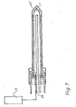
- a source 1 of a liquefied gas which can be liquid nitrogen at a pressure of more than 2 atmospheres (and preferably more than 5 atmospheres) a liquified noble gas or a miture of a liquefied noble gas with another cryocoolant.
- Source 1 is connected via a line 2 and an adjustable valve 3 to a flexible hose 4 leading to a cryoprobe 5.
- the liquefied gas is preferably liquefied xenon which, as previously explained, will result in the maximum cooling power in a cryoprobe of the presently described kind.
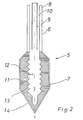
- the cryoprobe 5 comprises a shaft portion 6 and a cryotip 7.
- the shaft portion 6 serves to transfer the liquefied noble gas to the cryotip 7.
- the shaft portion comprises an inner tube 9 through which the liquefied gas enters the head portion 7.
- the cryotip 7 consists of a sintered metal body part 11 of a metal of low atomic number Z ⁇ 15 and indeed preferably of aluminium.
- a threaded passage 12 is provided inside the sintered body portion 11 so as to provide a large surface area for the transfer of heat from the sintered body portion to the cryocoolant. It will be appreciated that the rate of heat transfer is improved by the large surface area offered by the flanks of the threads 13.
- the body portion 11 converges to a sharp point which facilitates its introduction into body tissue.
- the sintered body portion is enclosed by a thin plated layer 14 of an inert metal which is also easy to sterilize.
- the inert metal is in this case gold, the large atomic number of gold is not however disadvantageous because the gold layer is very thin in comparison to the sintered body portion.
- This gas is collected for re-use either through a line running parallel to the flexible hose or through an outer annular passage coaxial to the feed passage through the flexible hose.
- the maximum diameter of the generally egg-shaped head portion 7 is approximately 5 mm, thus generating a cross-sectional area of the order of 20 square mm.
- the shaft portion is of smaller dimensions and preferably has an external diameter such that its cross-section is a maximum of 20 square mm and preferably 10 square mm.
- the threaded passage 12 will have a major diameter of, at the most, 2 mm and the remaining dimensions will be approximately as shown in the scale drawing of Figure 2.
- the heat exchanger is formed of a sintered metal such as aluminium (the sintered material has an even lower density than the straight metal), the heat exchanger is coated with a layer of aluminium to form a continuous outer shell which is substantially impermeable and this outer shell is then coated e.g. by plating, with a layer of gold which is substantially inert as far as body fluids are concerned.
- the outer shell can be formed by electroplating or using other known techniques.
- the cryotip can of course also be formed in a single piece of metal (plated if necessary).
- tubular wall structure 8 is a conventional vacuum wall structure i.e. comprises tubular inner and outer metallic walls separated by a vacuum cavity.
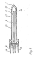
- cryotip 5 consists of a piece of solid aluminium which has been turned to provide an annular shoulder 20.
- This shoulder serves for attachment of the cryotip to the tubular wall structure 8 which, in this case, consists of plastic material, for example polyvinylchloride or PTFE.
- the tubular wall structure 8 comprises an inner tubular wall member 21 and an outer tubular wall member 22 which are spaced apart by two plastic spacers 23 and 24 at the axial ends of the tubular wall structure.
- the annular spacers 23 and 24 are secured to the inner and outer tubular members 21 and 22 by adhesive or by a plastic welding technique.
- the resulting tubular wall structure is secured to the cryotip at the shoulder either by means of adhesive or preferably by means of a fine screw thread (not shown) and a blocking adhesive.
- the end of the tubular structure remote from the cryotip is embedded in a block of plastic 25 which contains a number of passages and drillings which will now be explained in more detail.
- the inner tube 9 which is preferably a thin-walled aluminium tube includes a staggered portion 26 and a straight portion 27 which extends through the plastic block 25 and which provides the inlet connection for the supply of liquid cryocoolant.
- a second metallic thin walled tube 28 which extends parallel to the tube 27 through a passage in the plastic block 25 and which forms the outlet for the cryocoolant after the latter has passed through the cryotip 5.
- the inner and outer tubular wall members are spaced apart by the spacers 23, 24 to define a cavity 29.
- a cross-drilling 30 passes through the plastic block and through the tubular outer wall member to provide a passage communicating with the cavity 29.
- a tubular insert 31 extending parallel to the tube portions 27 and 28 breaks into the passage 30, which is plugged at its outer end, and provides an inlet for supplying a heating fluid to the cavity 29.
- a similar cross-drilling 32 and tubular insert 33 is provided for removing the heating fluid from the cavity 29.
- the cavity 29 includes two helical coils of plastic strip 34, 35, in the form of a two start thread.
- helical strips are so arranged that the heating fluid is caused to flow in a first helical path through the cavity 29 to the cryotip and back along a second parallel helical path to the outlet 33.
- the two helical coils 34 and 35 one can also use two partition walls extending in an axial direction.
- a heating fluid for example hot air is supplied to the passage 29 in order to prevent freezing at the outer surface of the tubular wall structure 8.
- this heating system it is generally not necessary to use this heating system until some time after an operation has commenced because it has been found that a considerable time is required for the outer wall surface of the tubular wall structure 8 to reach a temperature at which freezing of the surrounding tissues occurs.
- the cavity can conveniently be filled with a getter for residual gas such as activated carbon, and the tubes 31 and 33 sealed off, possibly after having effected a partial evacuation of the cavity 29.
- a getter for residual gas such as activated carbon
- FIG. 4 A similar arrangement to that shown in Figure 3 is illustrated in Figure 4.
- the cavity 29 is designed to accept a chemical or chemicals which generate heat exothermically.
- the chemicals which are preferably two liquids, are injected through the passage 31 using a hypodermic syringe at the start of the operation.
- the passage 31 is conveniently closed by a removable self- sealing rubber bung 36.
- the two chemicals can be selected so that the exothermic generation of heat takes place at an increasing rate so that the shaft portion is progressively heated as the operation takes place thus compensating for the otherwise decreasing temperature of the outer surface of the tubular wall structure 8.
- the second tube 33 can be used to extract the liquids after the reaction so that the cryoprobe can be prepared for re-use.
- one chemical can be introduced through the tube 31 and the second chemical through the tube 33 in order to prevent mixing of the two chemicals prior to insertion into the cryoprobe.
- the outer wall member 22 consists of a thin metal tube and a single chemical in the form of an acid is introduced into the cavity through the tubular insert 31. The acid is selected to exothermically etch away part of the inside of the tubular wall during the operation thus generating sufficient heat to prevent freezing of the tissue surrounding the shaft portion.
- FIG. 5 A further alternative embodiment in which provision is made for heating the outer surface of the shaft portion 8 is illustrated in Figure 5. Again common reference numerals are used to indicate parts which have counterparts in the previous embodiments.
- the outer tubular wall member consists of a translucent and preferably transparent plastic which is silvered at its inner surface to make it light reflecting and which is provided with an absorptive outer surface for example by blackening the outer surface.
- a laser light source 40 is connected to the resulting optical cavity 41 via a plurality of optical fibres 42 of which only two are shown in Figure 5 for the sake of simplicity.
- the tubular wall structure again features inner and outer tubular wall members 21 and 22 separated by a small cavity 29. It is however conceivable that this embodiment will work with solely a single tubular member due to the preferential heating of the outer surface.
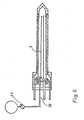
- FIG. 6 there can be seen an alternative design of cryoprobe which has provision for heating the cryotip after completion of the freezing phase so as to melt a layer of water around the tip and to facilitate its withdrawal from the patient.
- a source of heated gas for example hot air
- the tubular insert 28 normally used for removal of the cryocoolant from the cryoprobe.
- the tube 9 acts as the outlet for the heating fluid.
- a laser light source 45 may be used to heat the cryotip.
- a light guide for example in the form of a fibre or a bundle of optical fibres, extend from the laser through the tubular insert 28, or through a second specially provided tubular insert (not shown). Light from the laser is directed towards the cryotip which may be provided with a blackened surface 47 so that it is strongly absorbent. If the arrangement of Figure 7 is used with an arrangement similar to Figure 5, then the laser light source 40 can be used in place of the laser light source 45.
- cryotip is only schematically illustrated and it will be appreciated that the tip can, if desired, be made larger than the shaft and can, optionally, be constructed in the same manner as the cryotip of Figure 2.
- x-ray computer tomography can readily be used to monitor the development of the ice ball during use of any of the above- described cryoprobes for deep in-body surgery without the presence of the cryoprobe causing artefacts which confuse the radiographic image.
Landscapes
- Health & Medical Sciences (AREA)
- Surgery (AREA)
- Life Sciences & Earth Sciences (AREA)
- Nuclear Medicine, Radiotherapy & Molecular Imaging (AREA)
- Biomedical Technology (AREA)
- Engineering & Computer Science (AREA)
- Otolaryngology (AREA)
- Heart & Thoracic Surgery (AREA)
- Medical Informatics (AREA)
- Molecular Biology (AREA)
- Animal Behavior & Ethology (AREA)
- General Health & Medical Sciences (AREA)
- Public Health (AREA)
- Veterinary Medicine (AREA)
- Surgical Instruments (AREA)
Abstract
Description
- The present invention relates to cryosurgical apparatus especially for the cryosurgery of deeply lying lesions and tumors, and to a method of monitoring the progress of a cryogenic freezing process.
- During the last twenty years, cryosurgery has become established as an important clinical technique. Many investigations have been carried out in a search for a better understanding of the process.
- The destruction of tissues by cooling to cryogenic temperatures is usually effected with a cryoprobe. This instrument has a continuously cooled tip, the cryotip, which is placed on or into the tissue to be destroyed.
- By way of background information, the state of the art in cryoprobe design will now be described briefly. Reviews of some of the most popular designs have been published elsewhere, for example, G. Garamy in "Cryosurgery", edited by R. W. Rand et al., published in 1968 by C. C. Thomas in Springfield, U.S.A.; R. F. Barron in "Cryogenics in Surgery", edited by H. von Leden et al., published by Lewis in 1971 in London, and D. E. Wild in "Practical Cryosurgery", edited by H. B. Holden and published by Pitmann 1975 in London.
- There are two main types of cryoprobes currently in use:
- a) high-pressure probes that use Joule-Thompson expansion to cool the tip; and
- b) liquid nitrogen probes which use the latent heat of boiling nitrogen to cool the tip.
- One type of liquid nitrogen cryoprobe is disclosed in US-A-3,298,371. When used in the cryosurgery of deep lying tumors, it is essential to use a cryotip of small size, i.e. cryoprobes are required with very high cooling power. However, the cooling power of high pressure probes is not as good as the cooling power of liquid nitrogen devices and only the latter are considered in the following.
- Liquid nitrogen cryoprobes cool by boiling liquid nitrogen within the cryotip. It is possible to maintain a tip temperature close to the boiling point of nitrogen (-196°C at a pressure of one atmosphere) while extracting many watts of heat from the tissue. A typical liquid nitrogen system consists of:
- a) an appropriate vacuum storage flask for liquid nitrogen,
- b) transfer pipes and the associated valves,
- c) cryoprobe having a cryotip, i.e. that part which contacts the tissue, and
- d) means of controlling the cryoprobe cooling power including a device for monitoring the cryotip temperature.
- Liquid nitrogen devices give rise to problems with regard to cryogenic storage transfer. The liquid is stored in the vacuum flask and its transfer to the cryoprobe is ideally through a flexible hose. The shaft of the cryoprobe usually has to be contained within an evacuated sheath to prevent the outer casing from becoming too cold and to reduce boiling of the liquid nitrogen. A few cryoprobe designs have solved the problem of liquid nitrogen transfer by incorporating a small storage dewar into the cryotip itself, or by using the alternative technique of heating the transfer tubes to maintain the liquid in Leidenfrost flow.
- The cryoprobe can conveniently be considered as a shaft portion and a tip portion, i.e. the cryotip. The shaft portion is essentially the coolant transfer tube. In practice it may consist of an outer sheath, vacuum insulated from the cold, internal tube. The internal tube is subdivided into the liquid nitrogen channel and the cold gas sink. For most applications in deep-in-body cryosurgery, the cryotip should be rigid.
- The cryotip is the part of the cryoprobe in which the liquid coolant is boiled off due to heat exchange with the tissue. During cryotherapy it should be placed directly into the tissue to be destroyed.
- A number of theoretical studies together with measurements of the growing ice mass have afforded a reasonable understanding of the thermal effects of the cryoprobes. Monitoring the volume of the deeply frozen tissue which will be destroyed during thawing is very important if cryosurgery is to be a precise and practical medical tool. However, no satisfactory technique has so far been developed for these purposes. Usually one observes optically the development of the "ice-ball". However, this method is limited to external cryosurgery applications, for example of the skin, and is highly imprecise.
- The aim of cryosurgery is to kill all cells within a well-defined region. Investigations on cell tissues frozen in vitro have indicated two main mechanisms of cell destruction, i.e. extra and intra-cellular ice formation. As the extra-cellular ice grows, cell water passes out of the cell which causes the cell to shrink. Lethal cell damage occurs on thawing due to the large uptake of water into the cell and eventual rupture.
- Several authors have published theoretical models to describe the frozen mass of tissue, the "ice-ball".
- When a cryotip is placed in contact with tissue and cooled a temperature gradient develops in the tissue. The tissue adjacent the probe will undergo a phase change and, as the cooling continues, the freezing front will propagate through the tissue. Eventually, a steady state will be reached where the rate at which heat is extracted by the cryoprobe balances the rate at which it is supplied by the tissue.
- Cryosurgery has primary and secondary applications to diseases of the brain and spinal cord. Foremost has been its use in the production of discrete, destructive, thalamic lesions in the surgical treatment of Parkinson's disease and related disorders. Similarly, cryosurgery has been employed in the destruction of the normal pituitary gland, that is stereotactic-cryohypophysec- tomy, and in the treatment of selected cases of metastatic tumors. Cryosurgery is also useful in the management of difficult or unusual arterio- venous malformations of the brain and spinal cord and as an adjunct for other procedures, for example utilising the cryoprobe as a retractor in the micro-neurosurgical dissection of tumors and for the destruction of residual tumor tissues.
- Cryosurgery has been used in the treatment of selected cases of metastatic tumors on the surface and in body cavities. The cryotreatment of tumours deep inside the body has been prohibited by the lack of an appropriate monitoring technique.
- One of the main problems limiting the widespread use of cryosurgery is the difficulty of controlling the amount of tissue that is destroyed during the treatment. It should be pointed out that cryoprobes are a highly flexible source of cooling. The rate of cooling can be easily and precisely regulated. It has however proved very difficult to monitor the propagation of the freezing front inside the body. The classical ice-ball monitoring techniques are simply not good enough.
- For the cryosurgery of surface lesions (warts, skin tumors etc.) the extent of cryodestruction is usually assessed by the extent of the white frozen area generated. This has several disadvantages, namely: the volume of tissue destroyed is somewhat less than the volume of tissue cooled below 0°C; the volume of tissue destroyed depends on the cooling speed which is difficult to assess from the extent of frost on the skin; the visual check is valid for two dimensions. The depth of deep frozen tissue can only be estimated by assuming a hemispherical ice-ball shape.
- Cryoprobes have been described that are combined with endoscopes for use in cryoprostec- tomy, more recently, which are small enough to be introduced into the bladder or the uterus.
- The most common method of monitoring ice-ball growth, other than direct visional palpation, is the use of thermocouples. They are usually mounted in hypodermic needles and are placed on the outer border of the lesion prior to cryosurgery; the freezing process is continued until the thermocouples register a temperature below zero. Practically, the usefulness of this technique depends on how accurately the thermocouples are placed. Accurate positioning can be quite difficult if the site is not accessible.
- Changes in tissue impedance and of the current flowing between an active and a reference electrode placed in the frozen region have been studied. These measurements are claimed to be superior to temperature measurements because they give information about the volume ^f the tissue destroyed, rather than just about the volume of the ice-ball. For example the low frequency impedance rises rapidly at the eutectic point due to extracellular ice formation. However, these measurements give information only about the volume and not the shape of the ice-ball.
- Although measurements of the cryoprobe tip temperature have been shown to be unreliable as an indication of ice-ball size, it has been suggested that a heat flux measurement can be used. However, this can be used only for the initial stages of freeze.
- From this brief description it can be seen that the techniques appropriate for the precise monitoring, let alone imaging of the ice-ball development are missing. Furthermore, all the classical techniques are applicable only to the cryosurgery of tissue close to the body surface.
- It is a principle object of the present invention to provide improved cryosurgical apparatus for monitoring the growth of the ice-ball during cryosurgery, preferably by the use of three-dimensional imaging techniques, and, for this purpose, to provide an improved cryoprobe which makes the use of such improved imaging techniques practicable. Furthermore the present invention is also intended to provide apparatus which makes it possible for cryosurgery to be carried out at locations deep inside the body while still enabling monitoring of the cryosurgical operation.
- For these purposes the invention is also concerned with the provision of a cryoprobe of reduced size and adequate cooling power, which is constructed so as to allow the use of the monitoring technique proposed herein.
- According to the present invention, there is provided, starting from the prior art arrangement of US-A-3,298,371, cryosurgical apparatus comprising a cryoprobe including a hollow insu-t lated shaft portion having first and second ends, a cryotip mounted at said first end of said shaft portion and an inner tube extending inside said hollow insulated shaft portion from said second end to said first end and defining a passage between said inner tube and said hollow insulated shaft portion; a supply of liquid cryocoolant connectable to said inner tube for supplying cryocoolant to said cryotip through said inner tube, with said cryocoolant returning through said passage; characterised by the combination with an X-ray computer tomography installation for monitoring the developing of a cryosurgical tissue freezing process carried out using said cryoprobe; and in that at least said cryotip comprises substantially exclusively, with the possible exception of a thin external layer of a noble metal, of material having a low atomic number Z of less than 15.
- The invention is based on the recognition that by employing a cryotip of low atomic number it will be possible to use modern methods of medical imaging namely, x-ray computer tomography, to provide a three dimensional image of the ice-ball development and indeed without the image being significantly impaired by artifacts. This apparatus offers the further advantage that the diseased tissue, for example the tumor, the position of the cryotip and the temperature distribution around the cryotip can all be visualised at the same time.
- The absorption of x-rays (E=80 keV) in biological tissues is mainly due to Compton scattering. Thus, it is proportional to the tissue density. Using computer tomography, a density variation of a few parts per thousand can be detected. Manufacturers of CT scanners have chosen to relate attenuation specifically to water and air using a scale designed to produce a range of positive and negative integers for the materials of clinical interest, namely so-called Hausenfeld units (HU). For example, a change of density of 1% means a change of 10 HU.
- Water is the main component of almost all biological tissues, for example over 90% of both blood and muscular tissue. In the temperature range of interest, i.e. from the typical body temperature of 36.6 C down to the eutectic point of the intracellular fluid, ca. -21°C, the changes of density of water are rather large. For example, the density of water is 0.9935 g/cc at 36.6 C and 0.9999 g/cc at 0°C. The difference in density, about 0.6%, is detectable with CT systems. At the freezing point the density of ice is 0.9168 g/cc, i.e., the change in density due to the change in phase is 8.3% or 83 HU. Thus, the invention is based on the realisation that computer tomography will give an image of the propagation of the freezing front and some indication of the temperature gradients involved. The inventor has proved this experimentally by in vitro studies which show that the development of the ice-ball can be easily imaged using computer tomography. Studies have been made of many tissues of biological origin; cerebrospinal fluid, blood, animal fats, meat, white and grey brain matter. These results show that the change in density due to freezing is easily detectable by computer tomography and much higher than the natural variation of density in the tissues studied. Furthermore, the data derived to date suggest that, as expected, the largest part of the density change is due to phase change.
- The spatial resolution of modern CT installations is ca. 2 to 3 mm and the "slice thickness" is a few millimeters. The minimum time for reconstruction is a few seconds per slice. Thus, both the spatial and temporal resolutions of avilable CT systems are appropriate for imaging the growth of the ice-ball during cryosurgery. Real time imaging should permit feedback optimisation of cryosurgery procedures. Furthermore, cryosurgery of even the deepest internal organs becomes possible.
- As previously mentioned, the invention proposes the use of a cryotip of a material of low atomic number Z<15.
- A cryode used for cryosurgery of the body surface, e.g. of the skin, is admittedly known from EP-A-25021 which has a cryotip of aluminum. However, this cryode is in no way adapted for use for deep-in-body cryosurgery, as can be seen simply from the fact that it is very short and of relatively large diameter, so that it cannot be used to penetrate deeply in body tissue.
- Moreover, the cryode of EP-A-25021 is cooled by the Joule-Thompson effect, i.e. expansion of gas. For applications in cryosurgery deep in the body one however requires much higher cooling power, which is obtained in the present apparatus by the use of a liquid cryocoolant which extracts heat by evaporation inside the cryotip. EP-A-25021 does not in any way suggest the monitoring of the ice-ball via X-ray computer tomography.
- The material will, for practical reasons, normally be metal and indeed one of the group comprising lithium, beryllium, magnesium and aluminium or an alloy of any of these elements, either with themselves or with other elements.
- in a particularly practical embodiment the cryotip consists of an inner heat exchanger and a thin outer shell. The heat exchanger conveniently consists of a sintered metal.
- In this arrangement the shell is made of aluminium or another metal of low atomic number.
- In arrangements of this kind the outer shell is conveniently covered with a layer of noble metal, copper or chromium, having a thickness less than 0.5 mm and preferably less than 0.2 mm. This arrangement is not only relatively easy to manufacture but it also avoids corrosion of the outer shell and possible danger to the patient through the use of, for example beryllium.
- The aforementioned layer covering the outer shell is conveniently applied by plating.
- In an arrangement of the above-mentioned kind, the shaft portion preferably has a smaller cross-section than the cryotip. This arrangement is beneficial because it means that the shaft portion is less noticable in the image produced by computer tomography. In other words, the danger of creating artifacts is reduced, particularly at radiographically unfavourable angles of the cryoprobe which may be necessary in practice. The use of a shaft portion with a smaller cross-section than the cryotip is favourable in cases of deep-in-body surgery.
- In practice the invention envisages a cryoprobe in which the cryotip has a cross-sectional area smaller than 20 square mm and preferably smaller than 10 square mm. The cryotip will be preferably used with a shaft portion having a cross sectional area below 20 square mm.
- The cryotip is preferably egg-shaped with a relatively pointed front end which facilitates the introduction into body tissue for deep-in-body surgery. The pointed head allows the tissues to be pushed aside without being severed so that the damage caused to the body by the introduction of the cryotip is minimal. As the shaft in any case has a smaller diameter than the cryotip, the presence of the shaft is not objectionable.
- One particularly advantageous arrangement, which can also be used with conventional cryoprobes, comprises the use of a coolant comprising one of liquefied nitrogen at a pressure greater than two atmospheres, a liquefied noble gas, or a mixture of a liquefied noble gas with another cryocoolant. In one particularly advantageous arrangement the liquefied noble gas is helium kept in superfluid state i.e. below 2.15 K.
- An especially beneficial arrangement comprises the use of crypton or xenon or a mixture of these gases as the liquefied noble gas. This arrangement is particularly beneficial with a cryoprobe of small dimensions, in accordance with the present teaching, because it can be transferred through the relatively narrow shaft portion to the cryotip without suffering an undue pressure loss and can develop the maximum cooling power in the cryotip for a given size thereof.
- A further problem which is encountered with existing cryoprobes, and which becomes more critical as the shaft portion is made smaller in cross-section, is the problem of preventing the outside of the shaft portion from becoming too cool. In the case of deep-in-body cryosurgery, this cooling may cause damage of the tissue surrounding the shaft portion. Conventional cryoprobes use a vacuum jacket to prevent the cooling of the outside of the shaft portion. The use of a vacuum jacket becomes however increasingly difficult as the diameter of the shaft portion reduces. In order to overcome this difficulty the present invention proposes the arrangement set forth in
Claims 7 to 14. - According to a particularly favourable aspect of the invention there is provided, starting from the prior art of US-A-3,298,371 cryosurgical apparatus including a cryoprobe comprising an elongate shaft portion, a cryotip at one end of said shaft portion, a first passage defined within said shaft portion for conveying a liquid cryocoolant to the inside of the cryotip to cool the same, a second passage defined within said shaft for return flow of the cryocoolant, and means for heating said elongate shaft portion; characterised in that the external diameter of said elongate shaft portion is substantially the same size as or smaller than the external diameter of said cryotip; in that at least the cryotip consists of a material or materials of low atomic number Z:515, with the possible exception of a thin external layer of a noble metal; and in that the means for heating said shaft portion comprises a tubular structure defining an optical cavity having a reflective inner surface and an absorptive outer surface, and means for introducing light energy into said optical cavity.
- An additional problem which arises in cryosurgery is the difficulty of extracting the cryoprobe from the frozen tissue. It will be appreciated that the cryoprobe can only be withdrawn once the bond to the ice-ball has been broken. Release of the cryoprobe from the ice-ball can be achieved by heating the tip. A conventional method involves Joule heating of bulk resistor placed in the tip and is -considered undesirable as the resistor will probably cause artifacts in the image. In order to overcome this difficulty, the present invention proposes the arrangements set forth in Claims 15 and 16.
- Finally, the present invention also relates to a method of monitoring the progress of a cryogenic freezing process, other than a method of treating the human or animal body, comprising the use of x-ray computer tomography to visualise phase changes through the associated density changes.
- Embodiments of the invention will now be described by way of example and with reference to the drawings which show:
- Figure 1, a schematic illustration of a basic cryoprobe unit for cryotherapy, and
- Figure 2, a longitudinal section through a cryotip.
- Figure 3, a longitudinal section through an alternative cryoprobe with provision for heating the shaft portion thereof,
- Figure 4, a longitudinal section through a further alternative cryoprobe also with provision for heating the shaft portion thereof,
- Figure 5, a longitudinal section through a yet further alternative cryoprobe also with provision for heating the shaft portion thereof,
- Figure 6, a longitudinal section through another cryoprobe with provision for heating the cryotip, and,
- Figure 7, a longitudinal section through a cryoprobe similar to that of Figure 6 but with an alternative arrangement for heating the cryotip.
- Referring firstly to Figure 1, there can be seen a
source 1 of a liquefied gas, which can be liquid nitrogen at a pressure of more than 2 atmospheres (and preferably more than 5 atmospheres) a liquified noble gas or a miture of a liquefied noble gas with another cryocoolant.Source 1 is connected via aline 2 and anadjustable valve 3 to a flexible hose 4 leading to acryoprobe 5. In accordance with the invention the liquefied gas is preferably liquefied xenon which, as previously explained, will result in the maximum cooling power in a cryoprobe of the presently described kind. - As illustrated schematically in Figure 1, and in more detail in Figure 2, the
cryoprobe 5 comprises ashaft portion 6 and acryotip 7. Theshaft portion 6 serves to transfer the liquefied noble gas to thecryotip 7. For this purpose, the shaft portion comprises aninner tube 9 through which the liquefied gas enters thehead portion 7. Thecryotip 7 consists of a sinteredmetal body part 11 of a metal of low atomic number Z<15 and indeed preferably of aluminium. A threadedpassage 12 is provided inside thesintered body portion 11 so as to provide a large surface area for the transfer of heat from the sintered body portion to the cryocoolant. It will be appreciated that the rate of heat transfer is improved by the large surface area offered by the flanks of thethreads 13. At its front end, thebody portion 11 converges to a sharp point which facilitates its introduction into body tissue. - As previously mentioned, the sintered body portion is enclosed by a thin plated
layer 14 of an inert metal which is also easy to sterilize. The inert metal is in this case gold, the large atomic number of gold is not however disadvantageous because the gold layer is very thin in comparison to the sintered body portion. - After the liquefied gas or cryocoolant has entered the threaded
passage 12 of the body portion 11 a phase change occurs and the gas that is generated is extracted through the coaxial passage 10 defined between theinner tube 9 and thetubular wall structure 8 of the shaft portion. - This gas is collected for re-use either through a line running parallel to the flexible hose or through an outer annular passage coaxial to the feed passage through the flexible hose.
- The maximum diameter of the generally egg-shaped
head portion 7 is approximately 5 mm, thus generating a cross-sectional area of the order of 20 square mm. The shaft portion is of smaller dimensions and preferably has an external diameter such that its cross-section is a maximum of 20 square mm and preferably 10 square mm. The threadedpassage 12 will have a major diameter of, at the most, 2 mm and the remaining dimensions will be approximately as shown in the scale drawing of Figure 2. - In a particularly preferred arrangement not shown the heat exchanger is formed of a sintered metal such as aluminium (the sintered material has an even lower density than the straight metal), the heat exchanger is coated with a layer of aluminium to form a continuous outer shell which is substantially impermeable and this outer shell is then coated e.g. by plating, with a layer of gold which is substantially inert as far as body fluids are concerned. The outer shell can be formed by electroplating or using other known techniques.
- The cryotip can of course also be formed in a single piece of metal (plated if necessary).
- It will be appreciated in all the above embodiments that the
tubular wall structure 8 is a conventional vacuum wall structure i.e. comprises tubular inner and outer metallic walls separated by a vacuum cavity. - Returning now to Figure 3, there can be seen an alternative design of cryoprobe, the length of the shaft has however been considerably shortened for the purpose of illustration. In this case the
cryotip 5 consists of a piece of solid aluminium which has been turned to provide anannular shoulder 20. This shoulder serves for attachment of the cryotip to thetubular wall structure 8 which, in this case, consists of plastic material, for example polyvinylchloride or PTFE. Thetubular wall structure 8 comprises an innertubular wall member 21 and an outertubular wall member 22 which are spaced apart by twoplastic spacers annular spacers tubular members plastic 25 which contains a number of passages and drillings which will now be explained in more detail. - As can be seen the
inner tube 9 which is preferably a thin-walled aluminium tube includes a staggeredportion 26 and astraight portion 27 which extends through theplastic block 25 and which provides the inlet connection for the supply of liquid cryocoolant. Immediately above thetubular portion 27 there is illustrated a second metallic thinwalled tube 28 which extends parallel to thetube 27 through a passage in theplastic block 25 and which forms the outlet for the cryocoolant after the latter has passed through thecryotip 5. - As is clear from the drawing, the inner and outer tubular wall members are spaced apart by the
spacers cavity 29. A cross-drilling 30 passes through the plastic block and through the tubular outer wall member to provide a passage communicating with thecavity 29. Atubular insert 31 extending parallel to thetube portions passage 30, which is plugged at its outer end, and provides an inlet for supplying a heating fluid to thecavity 29. Asimilar cross-drilling 32 andtubular insert 33 is provided for removing the heating fluid from thecavity 29. Thecavity 29 includes two helical coils ofplastic strip cavity 29 to the cryotip and back along a second parallel helical path to theoutlet 33. In place of the twohelical coils - In practice, a heating fluid, for example hot air is supplied to the
passage 29 in order to prevent freezing at the outer surface of thetubular wall structure 8. In practice it is generally not necessary to use this heating system until some time after an operation has commenced because it has been found that a considerable time is required for the outer wall surface of thetubular wall structure 8 to reach a temperature at which freezing of the surrounding tissues occurs. In fact, for some applications, it may not be necessary to use a heating fluid at all and in this case the cavity can conveniently be filled with a getter for residual gas such as activated carbon, and thetubes cavity 29. One thus has a type of vacuum insulated structure which further impedes the cooling of the outer surface of thetubular wall structure 8. - A similar arrangement to that shown in Figure 3 is illustrated in Figure 4. The same reference numerals will be used in Figure 4 to designate parts which have counterparts in Figure 3. In the arrangement of Figure 4 the
cavity 29 is designed to accept a chemical or chemicals which generate heat exothermically. In this case the chemicals, which are preferably two liquids, are injected through thepassage 31 using a hypodermic syringe at the start of the operation. Thepassage 31 is conveniently closed by a removable self- sealingrubber bung 36. The two chemicals can be selected so that the exothermic generation of heat takes place at an increasing rate so that the shaft portion is progressively heated as the operation takes place thus compensating for the otherwise decreasing temperature of the outer surface of thetubular wall structure 8. Thesecond tube 33 can be used to extract the liquids after the reaction so that the cryoprobe can be prepared for re-use. Alternately one chemical can be introduced through thetube 31 and the second chemical through thetube 33 in order to prevent mixing of the two chemicals prior to insertion into the cryoprobe. In a further alternative version of this arrangement theouter wall member 22 consists of a thin metal tube and a single chemical in the form of an acid is introduced into the cavity through thetubular insert 31. The acid is selected to exothermically etch away part of the inside of the tubular wall during the operation thus generating sufficient heat to prevent freezing of the tissue surrounding the shaft portion. - A further alternative embodiment in which provision is made for heating the outer surface of the
shaft portion 8 is illustrated in Figure 5. Again common reference numerals are used to indicate parts which have counterparts in the previous embodiments. In the arrangement of Figure 5, the outer tubular wall member consists of a translucent and preferably transparent plastic which is silvered at its inner surface to make it light reflecting and which is provided with an absorptive outer surface for example by blackening the outer surface. Alaser light source 40 is connected to the resultingoptical cavity 41 via a plurality ofoptical fibres 42 of which only two are shown in Figure 5 for the sake of simplicity. Thermal energy in the form of light generated by thelaser 40 is thus introduced into theoptical cavity 41 and the light is progressively reflected from the silvered inner surface of thecavity 41 to the blackened outer surface where it is absorbed thus preferentially generating heating at the outer surface. In this embodiment the tubular wall structure again features inner and outertubular wall members small cavity 29. It is however conceivable that this embodiment will work with solely a single tubular member due to the preferential heating of the outer surface. - Turning now to Figure 6 there can be seen an alternative design of cryoprobe which has provision for heating the cryotip after completion of the freezing phase so as to melt a layer of water around the tip and to facilitate its withdrawal from the patient. In this embodiment a source of heated gas, for example hot air, can be connected via a
valve 44, to thetubular insert 28 normally used for removal of the cryocoolant from the cryoprobe. In this case thetube 9 acts as the outlet for the heating fluid. Clearly suitable valves are required in the inlet and outlet flow lines to enable the surgeon to select heating or cooling as required. In an alternative arrangement, Figure 7, alaser light source 45 may be used to heat the cryotip. For this purpose a light guide, for example in the form of a fibre or a bundle of optical fibres, extend from the laser through thetubular insert 28, or through a second specially provided tubular insert (not shown). Light from the laser is directed towards the cryotip which may be provided with a blackenedsurface 47 so that it is strongly absorbent. If the arrangement of Figure 7 is used with an arrangement similar to Figure 5, then thelaser light source 40 can be used in place of thelaser light source 45. - In all the embodiments of Figures 3 through 7 the cryotip is only schematically illustrated and it will be appreciated that the tip can, if desired, be made larger than the shaft and can, optionally, be constructed in the same manner as the cryotip of Figure 2.
- It will. be appreciated by the person averagely skilled in the art that x-ray computer tomography can readily be used to monitor the development of the ice ball during use of any of the above- described cryoprobes for deep in-body surgery without the presence of the cryoprobe causing artefacts which confuse the radiographic image.
Claims (19)
characterised in that the external diameter of said elongate shaft portion (6) is substantially the same size as or smaller than the external diameter of said cryotip (7); in that at least the cryotip (7) consists of a material or materials of low atomic number ZS15, with the possible exception of a thin external layer of a noble metal; and in that the means for heating said shaft portion comprises a tubular structure (22) defining an optical cavity (41) having a reflective inner surface and an absorptive outer surface, and means (40, 42) for introducing light energy into said optical cavity.
Applications Claiming Priority (2)
| Application Number | Priority Date | Filing Date | Title |
|---|---|---|---|
| GB8214331 | 1982-05-17 | ||
| GB8214331 | 1982-05-17 |
Publications (2)
| Publication Number | Publication Date |
|---|---|
| EP0108112A1 EP0108112A1 (en) | 1984-05-16 |
| EP0108112B1 true EP0108112B1 (en) | 1988-09-21 |
Family
ID=10530410
Family Applications (1)
| Application Number | Title | Priority Date | Filing Date |
|---|---|---|---|
| EP83901592A Expired EP0108112B1 (en) | 1982-05-17 | 1983-05-17 | Cryosurgical apparatus, especially for the cryosurgery of deeply lying lesions |
Country Status (3)
| Country | Link |
|---|---|
| EP (1) | EP0108112B1 (en) |
| DE (1) | DE3378018D1 (en) |
| WO (1) | WO1983003961A1 (en) |
Families Citing this family (31)
| Publication number | Priority date | Publication date | Assignee | Title |
|---|---|---|---|---|
| SU1417868A1 (en) * | 1985-11-20 | 1988-08-23 | Томский государственный медицинский институт | Cryoultrasonic scalpel |
| SU1563684A1 (en) * | 1986-05-26 | 1990-05-15 | Томский государственный медицинский институт | Cryosurgical scalpel |
| GB2236253A (en) * | 1989-09-23 | 1991-04-03 | Fern Dev Ltd | Cryosurgical probe |
| US5417686A (en) * | 1990-07-10 | 1995-05-23 | The Texas A&M University System | Temperature control mechanisms for a micro heat pipe catheter |
| GB9123413D0 (en) * | 1991-11-05 | 1991-12-18 | Clarke Brian K R | Method of thawing cryosurgical apparatus |
| US5324286A (en) * | 1993-01-21 | 1994-06-28 | Arthur A. Fowle, Inc. | Entrained cryogenic droplet transfer method and cryosurgical instrument |
| DE4436181A1 (en) * | 1994-10-10 | 1996-04-11 | Siemens Ag | Method and device for measuring an electrical variable with temperature compensation by fitting |
| EP1014873A4 (en) | 1997-09-22 | 2003-07-09 | Ethicon Inc | Cryosurgical system and method |
| US6589234B2 (en) * | 2001-09-27 | 2003-07-08 | Cryocath Technologies Inc. | Cryogenic medical device with high pressure resistance tip |
| US7479139B2 (en) * | 2002-01-04 | 2009-01-20 | Galil Medical Ltd. | Apparatus and method for protecting tissues during cryoablation |
| JP2007527728A (en) * | 2003-04-03 | 2007-10-04 | ガリル メディカル リミテッド | Apparatus and method for precisely defined cryoablation |
| WO2007057724A1 (en) * | 2005-11-17 | 2007-05-24 | Dieter Steinfatt | Hollow pin for the creation of frozen zones |
| WO2009007963A1 (en) * | 2007-07-09 | 2009-01-15 | Arbel Medical Ltd. | Cryosheath |
| US20110015624A1 (en) * | 2008-01-15 | 2011-01-20 | Icecure Medical Ltd. | Cryosurgical instrument insulating system |
| WO2009153755A2 (en) * | 2008-06-18 | 2009-12-23 | Arbel Medical Ltd. | Cryosurgical instrument insulating system |
| US7967814B2 (en) | 2009-02-05 | 2011-06-28 | Icecure Medical Ltd. | Cryoprobe with vibrating mechanism |
| WO2010105158A1 (en) | 2009-03-12 | 2010-09-16 | Icecure Medical Ltd. | Combined cryotherapy and brachytherapy device and method |
| US9498271B2 (en) | 2009-10-29 | 2016-11-22 | Cook Medical Technologies Llc | Coaxial needle cannula with distal spiral mixer and side ports for fluid injection |
| EP2542172B1 (en) | 2010-03-01 | 2018-07-11 | Cook Medical Technologies LLC | Thermo-chemical medical device for manipulation of tissue |
| US7967815B1 (en) | 2010-03-25 | 2011-06-28 | Icecure Medical Ltd. | Cryosurgical instrument with enhanced heat transfer |
| US7938822B1 (en) | 2010-05-12 | 2011-05-10 | Icecure Medical Ltd. | Heating and cooling of cryosurgical instrument using a single cryogen |
| US8080005B1 (en) | 2010-06-10 | 2011-12-20 | Icecure Medical Ltd. | Closed loop cryosurgical pressure and flow regulated system |
| RU2496442C2 (en) * | 2011-12-12 | 2013-10-27 | Федеральное государственное бюджетное учреждение науки Институт физики твердого тела Российской академии наук (ИФТТ РАН) | Cryonozzle with sapphire cold conductor-irradiator |
| RU2614104C1 (en) * | 2016-03-25 | 2017-03-22 | Общество с ограниченной ответственностью "МедСпецТруб" (ООО "МедСпецТруб") | Cryoprobe |
| US11413085B2 (en) | 2017-04-27 | 2022-08-16 | Medtronic Holding Company Sàrl | Cryoprobe |
| US20230270400A1 (en) * | 2018-01-15 | 2023-08-31 | Adam E.M. Eltorai | Low-artifact image-guided tumor ablation devices and method |
| US10610280B1 (en) | 2019-02-02 | 2020-04-07 | Ayad K. M. Agha | Surgical method and apparatus for destruction and removal of intraperitoneal, visceral, and subcutaneous fat |
| RU2719911C1 (en) * | 2019-11-19 | 2020-04-23 | Федеральное государственное бюджетное учреждение науки Институт физики твердого тела Российской академии наук (ИФТТ РАН) | Method for tracking depth of tissue freezing during cryodestruction and system for its implementation |
| US12426934B2 (en) | 2022-02-28 | 2025-09-30 | Icecure Medical Ltd. | Cryogen flow control |
| US12215811B2 (en) | 2022-07-18 | 2025-02-04 | Icecure Medical Ltd. | Cryogenic system connector |
| US12527613B2 (en) | 2023-09-11 | 2026-01-20 | Icecure Medical Ltd. | Cryoprobe |
Citations (1)
| Publication number | Priority date | Publication date | Assignee | Title |
|---|---|---|---|---|
| EP0025021A1 (en) * | 1979-08-02 | 1981-03-11 | M.C.S. Medical Constructions Service S.R.L. | Device for cryosurgical treatment with a high-efficiency heat exchange unit |
Family Cites Families (1)
| Publication number | Priority date | Publication date | Assignee | Title |
|---|---|---|---|---|
| US3298371A (en) * | 1965-02-11 | 1967-01-17 | Arnold S J Lee | Freezing probe for the treatment of tissue, especially in neurosurgery |
-
1983
- 1983-05-17 DE DE8383901592T patent/DE3378018D1/en not_active Expired
- 1983-05-17 EP EP83901592A patent/EP0108112B1/en not_active Expired
- 1983-05-17 WO PCT/EP1983/000124 patent/WO1983003961A1/en not_active Ceased
Patent Citations (1)
| Publication number | Priority date | Publication date | Assignee | Title |
|---|---|---|---|---|
| EP0025021A1 (en) * | 1979-08-02 | 1981-03-11 | M.C.S. Medical Constructions Service S.R.L. | Device for cryosurgical treatment with a high-efficiency heat exchange unit |
Also Published As
| Publication number | Publication date |
|---|---|
| WO1983003961A1 (en) | 1983-11-24 |
| EP0108112A1 (en) | 1984-05-16 |
| DE3378018D1 (en) | 1988-10-27 |
Similar Documents
| Publication | Publication Date | Title |
|---|---|---|
| EP0108112B1 (en) | Cryosurgical apparatus, especially for the cryosurgery of deeply lying lesions | |
| US6551309B1 (en) | Dual action cryoprobe and methods of using the same | |
| EP0925045B1 (en) | Cryoprobe | |
| US6505629B1 (en) | Cryosurgical system with protective warming feature | |
| US7410484B2 (en) | Cryotherapy probe | |
| Theodorescu | Cancer cryotherapy: evolution and biology | |
| US4646737A (en) | Localized heat applying medical device | |
| FI109329B (en) | Device for intra-stage burn care | |
| US9554842B2 (en) | Cryoprobe for low pressure systems | |
| AU660500B2 (en) | Cryosurgical instrument with vent holes and method | |
| EP2311398B1 (en) | Cryotherapy probe and system | |
| US6786902B1 (en) | Method and apparatus for cryosurgery | |
| US7479139B2 (en) | Apparatus and method for protecting tissues during cryoablation | |
| US20020022832A1 (en) | Cryoprobe assembly with detachable sheath | |
| JP2013539387A (en) | Cryoablation balloon catheter and related methods | |
| JP2009522037A (en) | Tissue thermal treatment system and method | |
| JP2009522037A5 (en) | ||
| WO2002053205A2 (en) | Systems and methods for delivering a probe into tissue | |
| CN101292897A (en) | Hot and cold probe therapy system | |
| Pushkarev et al. | Comparison of probe materials for tissue cryoablation: operational properties of metal and sapphire cryoprobes | |
| Rabin et al. | A compact cryosurgical apparatus for minimally invasive procedures | |
| Montmayeur et al. | The development of cryosurgical instruments for internal medicine | |
| Rothwarf et al. | A Versatile Low-Temperature Probe for Application to Cryosurgery | |
| WO2007073493A2 (en) | Cryoprobe with exhaust heater | |
| Lifton | Development of a flexible cryo-instrument for gastrointestinal endoscopy |
Legal Events
| Date | Code | Title | Description |
|---|---|---|---|
| PUAI | Public reference made under article 153(3) epc to a published international application that has entered the european phase |
Free format text: ORIGINAL CODE: 0009012 |
|
| AK | Designated contracting states |
Designated state(s): CH DE FR GB LI |
|
| 17P | Request for examination filed |
Effective date: 19840518 |
|
| RAP1 | Party data changed (applicant data changed or rights of an application transferred) |
Owner name: DRUKIER, ANDRZEJ KAMIL |
|
| GRAA | (expected) grant |
Free format text: ORIGINAL CODE: 0009210 |
|
| AK | Designated contracting states |
Kind code of ref document: B1 Designated state(s): CH DE FR GB LI |
|
| PG25 | Lapsed in a contracting state [announced via postgrant information from national office to epo] |
Ref country code: CH Effective date: 19880921 Ref country code: LI Effective date: 19880921 Ref country code: FR Free format text: THE PATENT HAS BEEN ANNULLED BY A DECISION OF A NATIONAL AUTHORITY Effective date: 19880921 |
|
| REF | Corresponds to: |
Ref document number: 3378018 Country of ref document: DE Date of ref document: 19881027 |
|
| REG | Reference to a national code |
Ref country code: CH Ref legal event code: PL |
|
| EN | Fr: translation not filed | ||
| PLBE | No opposition filed within time limit |
Free format text: ORIGINAL CODE: 0009261 |
|
| STAA | Information on the status of an ep patent application or granted ep patent |
Free format text: STATUS: NO OPPOSITION FILED WITHIN TIME LIMIT |
|
| PGFP | Annual fee paid to national office [announced via postgrant information from national office to epo] |
Ref country code: DE Payment date: 19890731 Year of fee payment: 7 |
|
| PGFP | Annual fee paid to national office [announced via postgrant information from national office to epo] |
Ref country code: GB Payment date: 19890831 Year of fee payment: 7 |
|
| 26N | No opposition filed | ||
| PG25 | Lapsed in a contracting state [announced via postgrant information from national office to epo] |
Ref country code: GB Effective date: 19900517 |
|
| GBPC | Gb: european patent ceased through non-payment of renewal fee | ||
| PG25 | Lapsed in a contracting state [announced via postgrant information from national office to epo] |
Ref country code: DE Effective date: 19910201 |