EP0108182B1 - Stangenführungsvorrichtung für Mehrspindel-Drehmaschinen - Google Patents
Stangenführungsvorrichtung für Mehrspindel-Drehmaschinen Download PDFInfo
- Publication number
- EP0108182B1 EP0108182B1 EP82810472A EP82810472A EP0108182B1 EP 0108182 B1 EP0108182 B1 EP 0108182B1 EP 82810472 A EP82810472 A EP 82810472A EP 82810472 A EP82810472 A EP 82810472A EP 0108182 B1 EP0108182 B1 EP 0108182B1
- Authority
- EP
- European Patent Office
- Prior art keywords
- distributor
- bar
- tube
- piston
- tubes
- Prior art date
- Legal status (The legal status is an assumption and is not a legal conclusion. Google has not performed a legal analysis and makes no representation as to the accuracy of the status listed.)
- Expired
Links
- 239000012530 fluid Substances 0.000 claims description 13
- 238000005520 cutting process Methods 0.000 claims description 5
- 239000000839 emulsion Substances 0.000 claims description 4
- 238000003780 insertion Methods 0.000 claims description 2
- 230000037431 insertion Effects 0.000 claims description 2
- 210000004013 groin Anatomy 0.000 claims 3
- 238000002347 injection Methods 0.000 claims 1
- 239000007924 injection Substances 0.000 claims 1
- 239000003921 oil Substances 0.000 description 15
- 238000003754 machining Methods 0.000 description 7
- 230000006866 deterioration Effects 0.000 description 4
- 239000011521 glass Substances 0.000 description 3
- 238000010276 construction Methods 0.000 description 2
- 238000009826 distribution Methods 0.000 description 2
- 238000004519 manufacturing process Methods 0.000 description 2
- 239000000463 material Substances 0.000 description 2
- 229910000831 Steel Inorganic materials 0.000 description 1
- 239000000498 cooling water Substances 0.000 description 1
- 239000010730 cutting oil Substances 0.000 description 1
- 238000006073 displacement reaction Methods 0.000 description 1
- 230000008030 elimination Effects 0.000 description 1
- 238000003379 elimination reaction Methods 0.000 description 1
- 230000002349 favourable effect Effects 0.000 description 1
- 238000009434 installation Methods 0.000 description 1
- 239000011810 insulating material Substances 0.000 description 1
- 238000009413 insulation Methods 0.000 description 1
- 238000005461 lubrication Methods 0.000 description 1
- 238000004064 recycling Methods 0.000 description 1
- 239000000344 soap Substances 0.000 description 1
- 239000010959 steel Substances 0.000 description 1
- XLYOFNOQVPJJNP-UHFFFAOYSA-N water Substances O XLYOFNOQVPJJNP-UHFFFAOYSA-N 0.000 description 1
Images



Classifications
-
- B—PERFORMING OPERATIONS; TRANSPORTING
- B23—MACHINE TOOLS; METAL-WORKING NOT OTHERWISE PROVIDED FOR
- B23B—TURNING; BORING
- B23B13/00—Arrangements for automatically conveying or chucking or guiding stock
- B23B13/04—Arrangements for automatically conveying or chucking or guiding stock for turning-machines with a plurality of working-spindles
-
- B—PERFORMING OPERATIONS; TRANSPORTING
- B23—MACHINE TOOLS; METAL-WORKING NOT OTHERWISE PROVIDED FOR
- B23B—TURNING; BORING
- B23B13/00—Arrangements for automatically conveying or chucking or guiding stock
- B23B13/02—Arrangements for automatically conveying or chucking or guiding stock for turning-machines with a single working-spindle
- B23B13/027—Feeding by pistons under fluid-pressure
-
- Y—GENERAL TAGGING OF NEW TECHNOLOGICAL DEVELOPMENTS; GENERAL TAGGING OF CROSS-SECTIONAL TECHNOLOGIES SPANNING OVER SEVERAL SECTIONS OF THE IPC; TECHNICAL SUBJECTS COVERED BY FORMER USPC CROSS-REFERENCE ART COLLECTIONS [XRACs] AND DIGESTS
- Y10—TECHNICAL SUBJECTS COVERED BY FORMER USPC
- Y10T—TECHNICAL SUBJECTS COVERED BY FORMER US CLASSIFICATION
- Y10T82/00—Turning
- Y10T82/25—Lathe
- Y10T82/2514—Lathe with work feeder or remover
- Y10T82/2516—Magazine type
- Y10T82/2518—Bar feeder
Definitions
- the present invention relates to a bar guide device for a multispindle lathe comprising a plurality of guide tubes, each of said tubes supporting a bar for machining in rotation a fluid distributor placed at the rear of said tubes to control the advance of a supporting piston. and centering the rear of said bar in the tube.
- the known devices consist of a barrel of steel tube, the advance of the bar being made, in general, by an advance clamp located in the headstock of the lathe. Due to the low rotational speeds, it is relatively easy to absorb the noise generated by the vibrations of the rotating bars, either by placing insulating materials around the barrel tubes, or by padding the whole so as to suppress noise towards outside. These soundproofing means are however not satisfactory, given that the noise is only a result of the vibrations and that even if perfect acoustic insulation were achieved, the vibrations of the bar which are transmitted would not be suppressed. along it in the machining area of the parts, which causes deterioration of surface conditions and difficulties in terms of tolerances, as well as deterioration of cutting tools.
- the bar guide It is obligatory to use in the bar guide the same oil or cooling water which is used in the machining area of the bar. These two conditions are completely incompatible.
- the fluids capable of achieving a hydrodynamic bearing in such an application do not have the same characteristics such as viscosity, emulsion, etc. as the fluid (for example soap water) intended to cool the cutting tools.
- the guide tubes of and known devices are generally in mechanically welded construction. The inside diameter of the barrel tubes being chosen according to the maximum capacity of the lathe. It is therefore not possible to choose the inside diameter as required.
- US Pat. No. 2,548,786 shows a bar guide device for a multispindle lathe in which two sets of guide tubes are disposed respectively in two diverging planes capable of tilting about a common axis located at their base. Each tube contains a pneumatically controlled push piston to advance the bars to be machined towards the lathe spindles. At the rear of the guide tubes is disposed a set of extension tubes designed to receive the push pistons of a set of guide tubes to be refueled.
- the bars to be machined are not supported in their respective guide tubes by a hydrodynamic bearing, so that the problems of vibration of the rotating bars are not solved.
- the known device therefore does not allow high speeds of rotation of the bars.
- the object of the present invention is to provide a bar guide device for a multi-spindle lathe making it possible to guide and advance the bars to be machined by suppressing the vibrations of the latter so as to reduce the noise.
- the device must be able to adapt to all existing dimensions and current profiles and allow easy automation of bar refueling.
- the device according to the invention is produced as described in claim 1.
- the vibrations are very greatly reduced and the noise caused by the bar guide is lower than the noise level of the lathe.
- This allows the device to be used in multi-spindle lathes turning at high speeds which have not yet been achieved and an improvement in machining precision.
- bar refueling is quick and easy, which increases production capacity.
- the piston being capable of controlling the advance of the bar in its tube, it is possible to remove the advance clamp normally provided on the multi-spindle lathe.
- the movement of the dispenser during refueling can be automated in a simple and inexpensive manner.
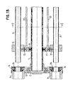
- the device includes a barrel, removable guide tubes and a hydraulic distributor.
- the barrel consists of a central shaft 1, a front disc 2 grafted onto the rear of the multi-spindle lathe, intermediate discs 3 and a rear disc 4.
- the discs 3 and 4 are mounted on the central shaft by adjustable clamping rings 13 to allow adjustment of the discs on the shaft.
- the guide tubes 5 of the bars (not shown) are held in rings 6 supported by seals 23 on the intermediate discs 3 to which these rings are fixed by flanges 7 ( Figure 2).
- the disc 4 is mounted in a socket 9 integral with the guide tube 5.
- the discs 3 and 4 therefore make it possible to position and hold in place the guide tubes 5.
- the latter are removable and easily interchangeable to adapt to the dimensions of the bars to machine.
- the rear disc 4 rests on the chassis 29 of the machine by ball bearings 30. This chassis maintains the entire device in alignment with the multi-spindle lathe.
- On the disc 2 are mounted centering glasses 14 fixed by flanges 15 to this disc 2. These centering glasses have ball bearings 16 and allow by means of removable support rings 34 whose diameter and profile can be adapted to the diameter and profile of the bars to be machined, to support the bars, see the piston, between the end of the guide tubes 5 and the headstock (not shown) of the lathe. They therefore serve as intermediate supports.
- These rings 34 are made of deformable material capable of accepting the deformations of the bars and of absorbing the vibrations of the latter.
- the distributor 11 in the form of a disc integral with the machine, is located at the rear of the disc 4 and it is mounted on the central shaft 1 by a bearing 17. It is closed at the rear by a closing plate 18.
- the function of the distributor is to distribute the pressurized oil from a hydraulic group (not shown) having several pressure sources and to distribute this oil in the barrel guide tubes.
- the oil is supplied by two pressure sources.
- the first pressure source supplies the input 11 A which corresponds to the supply of the guide tube located in the bar refueling position.
- the inlet 11A is located in the closing plenum 18.
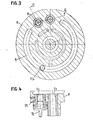
- the second pressure source is connected to the inlet 11B of the distributor for the supply by grooves 19 (FIG. 3) of all the other guide tubes 5.
- the pressurized oil is distributed by lines 20 in the intermediate discs 3 and, from these discs, it is injected laterally by non-return valves 21 between the guide tubes and the bars to be machined in rotation in these tubes, in order to allow hydrodynamic lift at least from the middle part of these bars.
- the dispenser further comprises an opening 11 C provided for the introduction of a new bar to be machined in an empty guide tube being in the refueling position. .
- the bush 10 which is to be changed when the diameter of the guide tubes 5 is changed, as well as the piston 8A, 8B also form part of the guide tube 5.
- the length of the distributor 11 is such that it accepts the piston 8A, 8B entirely withdrawn from the guide tube.
- the piston has a rear part 8B whose advance in the guide tube is produced by the pressure of the hydraulic fluid but which does not rotate relative to this tube, and a front part 8A capable of rotating in a bearing of the rear part 8B .
- the front part 8A of the piston is rotated by the bar to be machined against the rear of which it is pressed by the pressure of the fluid on the rear part 8B.
- the inlet 11A of the distributor 11 is placed under vacuum, which causes the piston which was at the left end (in FIG. 1) of the empty guide tube to move back.
- This piston enters the distributor housing provided for this purpose, as shown in Figure 1.
- all the other tubes remain under pressure through the supply 11 B.
- a pusher 27 acting for example on a microswitch (not shown) and the distributor with the piston 8A, 8B is rotated manually or automatically around the axis of the central tube 1 of so as to present position 11 C opposite the empty tube.
- the plug 12 closing the rear of the opening 11 C is removed and a new bar is introduced through this opening in the guide tube.
- the plug 12 is then replaced, the distributor 11 is rotated around the axis of the central tube 1 until its position 11A is opposite the tube which has just been refueled and the oil pressure is again applied in the inlet 11 A so that the piston comes to support the rear of the new bar inserted.
- the machine starts up again and the machining takes place until the next "end of bar" signal.
- Indexing in a normal work cycle, is normally carried out in a fraction of a second.
- the oil pressure of the inlet 11A on the piston which is in the tube which leaves the working position 11A no longer acts for a fraction of a second on the rear of this piston, but this is of no consequence for the proper functioning of the device by the fact that the rear part of the guide tubes, filled with pressurized oil, acts as an accumulator and that the pressure does not have time to drop below the pressure minimum required for such a short period of time.
- the passage of a tube from the refueling position to the next position must be done by position 11C and the plug 12 is sealed by a seal 28 to prevent the oil from escaping through this opening during this passage.
- the rear of the bars to be machined is continuously supported and centered by the front part 8A of the piston which rotates with the bar. This makes it possible to prevent the rear of the bar from floating in its tube and coming to beat the internal wall of this tube.
- the vibrations of the bar supported at the front in the centering glasses 14 and at the rear by the piston are mainly eliminated thanks to the hydrodynamic bearing which avoids any metallic contact between the rotating bar and the stationary guide tube. . 11 results in a much quieter operation, the noise level of the device being lower than that of the multi-spindle lathe and an improvement in the precision of the machining and of the surface conditions. The deterioration of the cutting tools due to vibrations is also greatly reduced.
- the hydrodynamic lift at least from the middle part of the bars makes it possible to give the bars to be machined a high speed of rotation in the tube which was not achievable until now.
- the profile of the bars is not limited to a round section but the device accepts any existing profile such as square, six panels, etc.
- the clearance between the bar and the inner wall of the tube depends on the speed of rotation, it is normally between 2 and 6 mm, which allows a certain floating of the middle part of a long bar in its tube.
- the oil injected laterally by the non-return valves 21 between the bar and the internal wall of the tube the bar never comes into contact with this wall.
- the fluid contained in the tube under a pressure caused by turbulence due to the rotation of the bar and function of the clearance mentioned above flows through the left end (figure 1) of this tube and it is recovered in closed circuit in the hydraulic unit.
- a hydraulic or pneumatic control cylinder 33 removes the plug 12 for closing the opening 11C of the distributor and a second hydraulic or pneumatic cylinder 31 ( 5) then acts on the lever 32 for the radial displacement of the distributor 11 to bring the opening 11 C in front of the empty tube to be refueled located in the refueling position 11A, to allow the insertion of a new bar in this tube through opening 11C.
- the use of a commercial bar feeder then allows a fully automatic refueling.
- the device according to the invention also makes it possible to eliminate the advance clamps normally provided on multi-spindle lathes. To do this, simply take the following steps.
- the piston 8A, 8B must be extended so as to be introduced over its entire length between the centering bezel 14 and the front of the headstock of the lathe.
- the recess for the piston in the valve 11 must be extended accordingly, to fully accept the piston when refueling the bars.
- the disadvantages or disadvantages of the advance grippers are as follows: they are expensive, subject to wear requiring recycling, they cause a deterioration of the surface condition of the bar and they make the introduction of a new bar difficult. to machine.
- the elimination of these grippers in advance using the device according to the invention therefore brings a new favorable contribution in the field of multi-spindle lathes.
Landscapes
- Engineering & Computer Science (AREA)
- Mechanical Engineering (AREA)
- Turning (AREA)
Claims (11)
Priority Applications (4)
| Application Number | Priority Date | Filing Date | Title |
|---|---|---|---|
| EP82810472A EP0108182B1 (de) | 1982-11-05 | 1982-11-05 | Stangenführungsvorrichtung für Mehrspindel-Drehmaschinen |
| DE8282810472T DE3274726D1 (en) | 1982-11-05 | 1982-11-05 | Stock bar guiding device for multi-spindle lathes |
| US06/540,383 US4679470A (en) | 1982-11-05 | 1983-10-11 | Guide-bar device for multi-spindle lathe |
| JP58207326A JPS59232701A (ja) | 1982-11-05 | 1983-11-04 | 多軸旋盤のための案内棒装置 |
Applications Claiming Priority (1)
| Application Number | Priority Date | Filing Date | Title |
|---|---|---|---|
| EP82810472A EP0108182B1 (de) | 1982-11-05 | 1982-11-05 | Stangenführungsvorrichtung für Mehrspindel-Drehmaschinen |
Publications (2)
| Publication Number | Publication Date |
|---|---|
| EP0108182A1 EP0108182A1 (de) | 1984-05-16 |
| EP0108182B1 true EP0108182B1 (de) | 1986-12-17 |
Family
ID=8190085
Family Applications (1)
| Application Number | Title | Priority Date | Filing Date |
|---|---|---|---|
| EP82810472A Expired EP0108182B1 (de) | 1982-11-05 | 1982-11-05 | Stangenführungsvorrichtung für Mehrspindel-Drehmaschinen |
Country Status (4)
| Country | Link |
|---|---|
| US (1) | US4679470A (de) |
| EP (1) | EP0108182B1 (de) |
| JP (1) | JPS59232701A (de) |
| DE (1) | DE3274726D1 (de) |
Families Citing this family (8)
| Publication number | Priority date | Publication date | Assignee | Title |
|---|---|---|---|---|
| DE8814860U1 (de) * | 1988-11-29 | 1989-02-16 | Wilhelm Hainbuch GmbH u. Co Präzisions-Spannwerkzeugfabrik, 7142 Marbach | Zuführvorrichtung für die Dämpfungsflüssigkeit in Führungsrohren bei Mehrspindel-Drehmaschinen und dgl. |
| DE3926841A1 (de) * | 1989-08-14 | 1991-02-21 | Hainbuch Praez Spannwerkzeug | Fuehrungsvorrichtung fuer stangenfoermige werkstuecke von drehmaschinen |
| DE3927532A1 (de) * | 1989-08-21 | 1991-02-28 | Hainbuch Praez Spannwerkzeug | Zufuehrvorrichtung fuer die daempfungsfluessigkeit in fuehrungsrohren bei mehrspindel-drehmaschinen und dergl. |
| DE4428352A1 (de) * | 1993-08-17 | 1995-02-23 | Nat Acme Co | Verfahren und Vorrichtung zum Zuführen von Stangenmaterial |
| US5617769A (en) * | 1994-10-14 | 1997-04-08 | Hardinge Brothers, Inc. | Thermally compliant bar feeding machine |
| EP0776718B1 (de) * | 1995-11-28 | 2001-10-31 | CUCCHI GIOVANNI & C. S.r.l. | Stangenzuführvorrichtung mit schaltbarem Vorschub für Mehrspindeldrehmaschinen |
| JP3713397B2 (ja) * | 1998-10-02 | 2005-11-09 | 株式会社育良精機製作所 | 棒材加工装置および棒材供給機 |
| SE520961C2 (sv) * | 2001-06-12 | 2003-09-16 | Tomas Gunnarsson | Hydraulsystem ingående i maskin såsom bearbetningsfixtur |
Family Cites Families (8)
| Publication number | Priority date | Publication date | Assignee | Title |
|---|---|---|---|---|
| US2548786A (en) * | 1947-07-05 | 1951-04-10 | Lipe Rollway Corp | Breech-loading bar feed mechanism |
| US3823628A (en) * | 1971-08-03 | 1974-07-16 | Fortune William S | Raw material feeder system |
| GB1416615A (en) * | 1973-08-21 | 1975-12-03 | Twyford Moors Aircraft & Eng | Bar holder and feeder coupled to an automatic machine tool |
| CA1003626A (en) * | 1973-09-28 | 1977-01-18 | Robert A. Cottingham | Bar stock guide tubes for metal working machines and sound-damping liners for such tubes |
| CH576304A5 (de) * | 1973-10-16 | 1976-06-15 | Scheurer Philippe | |
| DE2731735A1 (de) * | 1977-07-11 | 1979-02-01 | Vente De Fabrication Pour Le D | Druckmittelgesteuerte stangenvorschubeinrichtung fuer einen drehautomaten |
| CH622196A5 (de) * | 1978-05-19 | 1981-03-31 | Lns Sa | |
| US4421446A (en) * | 1981-07-23 | 1983-12-20 | Manurhin Automatic Division Of Mitac, Inc. | Bar feed mechanism |
-
1982
- 1982-11-05 EP EP82810472A patent/EP0108182B1/de not_active Expired
- 1982-11-05 DE DE8282810472T patent/DE3274726D1/de not_active Expired
-
1983
- 1983-10-11 US US06/540,383 patent/US4679470A/en not_active Expired - Fee Related
- 1983-11-04 JP JP58207326A patent/JPS59232701A/ja active Pending
Also Published As
| Publication number | Publication date |
|---|---|
| JPS59232701A (ja) | 1984-12-27 |
| EP0108182A1 (de) | 1984-05-16 |
| DE3274726D1 (en) | 1987-01-29 |
| US4679470A (en) | 1987-07-14 |
Similar Documents
| Publication | Publication Date | Title |
|---|---|---|
| EP0108182B1 (de) | Stangenführungsvorrichtung für Mehrspindel-Drehmaschinen | |
| FR2558753A1 (fr) | Cassette porte-outil a vitesse rapide adaptable sur des perceuses, fraiseuses ou autres machines-outils similaires | |
| EP0121638B1 (de) | Stangenführungsvorrichtung für Mehrspindeldrehmaschinen | |
| CH657794A5 (fr) | Bloc-palier, ravitailleur, notamment pour tour automatique, comprenant de tels blocs-paliers, utilisation de ce bloc-palier. | |
| EP0806264B1 (de) | Werkzeugmaschine mit Exzenterspindel | |
| EP0070073B1 (de) | Zuführeinrichtung für automatische Drehbänke und deren Herstellung | |
| FR2612438A1 (fr) | Machine-outil, notamment perceuse ou taraudeuse | |
| EP0214926B1 (de) | Stangenführungsvorrichtung | |
| EP0356389B1 (de) | Antriebsvorrichtung für eine Mehrspindelbearbeitungsmaschine | |
| FR2541607A1 (fr) | Porte-outil pour perceuses, fraiseuses et machines-outils analogues | |
| FR2511281A1 (fr) | Dispositif de retenue d'un corps rotatif autour d'un axe non coaxial a son arbre d'entrainement | |
| FR2532572A1 (fr) | Tete porte-broche pour machine-outil | |
| FR2566690A1 (fr) | Taraudeuse | |
| EP0180686A1 (de) | Stangenführungsvorrichtung für Mehrspindeldrehmaschine | |
| EP0044815A1 (de) | Führungsausrüstung für Stangen in einem Drehautomaten | |
| EP0128257B1 (de) | Verfahren zum Zuführen von Stangen bei einer Drehbank | |
| EP0052023B1 (de) | Numerisch gesteuerte Werkzeugmaschine mit Werkzeugmagazin | |
| CH647968A5 (en) | Rotary rest | |
| FR3166942A1 (fr) | Bague antivibration pour le forage, en particulier d’un arbre de turbine de turbomachine d’aéronef | |
| CH661889A5 (fr) | Dispositif de support sans centre pour une piece a usiner dans une machine a meuler. | |
| EP0363328B1 (de) | Werkzeugmaschinenspindel | |
| CH659964A5 (fr) | Dispositif d'echange d'une pince de serrage dans une machine-outil. | |
| FR3067271B1 (fr) | Machine-outil avec dispositif d'alignement des broches | |
| CH641073A5 (en) | Feed mechanism for an automatic lathe | |
| FR2719512A1 (fr) | Dispositif d'usinage d'une zone de jonction entre une tuyauterie principale et une tuyauterie de piquage rapportée. |
Legal Events
| Date | Code | Title | Description |
|---|---|---|---|
| PUAI | Public reference made under article 153(3) epc to a published international application that has entered the european phase |
Free format text: ORIGINAL CODE: 0009012 |
|
| AK | Designated contracting states |
Designated state(s): CH DE FR GB IT LI SE |
|
| RAP1 | Party data changed (applicant data changed or rights of an application transferred) |
Owner name: SAMECA S.A. |
|
| RAP1 | Party data changed (applicant data changed or rights of an application transferred) |
Owner name: SAMECA S.A. |
|
| RBV | Designated contracting states (corrected) |
Designated state(s): CH DE FR GB IT LI SE |
|
| 17P | Request for examination filed |
Effective date: 19841112 |
|
| ITF | It: translation for a ep patent filed | ||
| GRAA | (expected) grant |
Free format text: ORIGINAL CODE: 0009210 |
|
| AK | Designated contracting states |
Kind code of ref document: B1 Designated state(s): CH DE FR GB IT LI SE |
|
| REF | Corresponds to: |
Ref document number: 3274726 Country of ref document: DE Date of ref document: 19870129 |
|
| PLBE | No opposition filed within time limit |
Free format text: ORIGINAL CODE: 0009261 |
|
| STAA | Information on the status of an ep patent application or granted ep patent |
Free format text: STATUS: NO OPPOSITION FILED WITHIN TIME LIMIT |
|
| 26N | No opposition filed | ||
| ITTA | It: last paid annual fee | ||
| EAL | Se: european patent in force in sweden |
Ref document number: 82810472.9 |
|
| PGFP | Annual fee paid to national office [announced via postgrant information from national office to epo] |
Ref country code: GB Payment date: 19971121 Year of fee payment: 16 |
|
| PGFP | Annual fee paid to national office [announced via postgrant information from national office to epo] |
Ref country code: SE Payment date: 19971124 Year of fee payment: 16 |
|
| PGFP | Annual fee paid to national office [announced via postgrant information from national office to epo] |
Ref country code: FR Payment date: 19971127 Year of fee payment: 16 |
|
| PGFP | Annual fee paid to national office [announced via postgrant information from national office to epo] |
Ref country code: DE Payment date: 19971128 Year of fee payment: 16 |
|
| PGFP | Annual fee paid to national office [announced via postgrant information from national office to epo] |
Ref country code: CH Payment date: 19980303 Year of fee payment: 16 |
|
| PG25 | Lapsed in a contracting state [announced via postgrant information from national office to epo] |
Ref country code: GB Free format text: LAPSE BECAUSE OF NON-PAYMENT OF DUE FEES Effective date: 19981105 |
|
| PG25 | Lapsed in a contracting state [announced via postgrant information from national office to epo] |
Ref country code: SE Free format text: LAPSE BECAUSE OF NON-PAYMENT OF DUE FEES Effective date: 19981106 |
|
| PG25 | Lapsed in a contracting state [announced via postgrant information from national office to epo] |
Ref country code: LI Free format text: LAPSE BECAUSE OF NON-PAYMENT OF DUE FEES Effective date: 19981130 Ref country code: CH Free format text: LAPSE BECAUSE OF NON-PAYMENT OF DUE FEES Effective date: 19981130 |
|
| GBPC | Gb: european patent ceased through non-payment of renewal fee |
Effective date: 19981105 |
|
| REG | Reference to a national code |
Ref country code: CH Ref legal event code: PL |
|
| PG25 | Lapsed in a contracting state [announced via postgrant information from national office to epo] |
Ref country code: FR Free format text: LAPSE BECAUSE OF NON-PAYMENT OF DUE FEES Effective date: 19990730 |
|
| EUG | Se: european patent has lapsed |
Ref document number: 82810472.9 |
|
| REG | Reference to a national code |
Ref country code: FR Ref legal event code: ST |
|
| PG25 | Lapsed in a contracting state [announced via postgrant information from national office to epo] |
Ref country code: DE Free format text: LAPSE BECAUSE OF NON-PAYMENT OF DUE FEES Effective date: 19990901 |