EP0108198A2 - Verfahren zum Betreiben eines Reaktors zur Erzeugung von Synthesegas und Vorrichtung zur Durchführung des Verfahrens - Google Patents
Verfahren zum Betreiben eines Reaktors zur Erzeugung von Synthesegas und Vorrichtung zur Durchführung des Verfahrens Download PDFInfo
- Publication number
- EP0108198A2 EP0108198A2 EP83107640A EP83107640A EP0108198A2 EP 0108198 A2 EP0108198 A2 EP 0108198A2 EP 83107640 A EP83107640 A EP 83107640A EP 83107640 A EP83107640 A EP 83107640A EP 0108198 A2 EP0108198 A2 EP 0108198A2
- Authority
- EP
- European Patent Office
- Prior art keywords
- gas
- reactor
- synthesis gas
- oxygen
- regenerator
- Prior art date
- Legal status (The legal status is an assumption and is not a legal conclusion. Google has not performed a legal analysis and makes no representation as to the accuracy of the status listed.)
- Granted
Links
Images

Classifications
-
- C—CHEMISTRY; METALLURGY
- C10—PETROLEUM, GAS OR COKE INDUSTRIES; TECHNICAL GASES CONTAINING CARBON MONOXIDE; FUELS; LUBRICANTS; PEAT
- C10J—PRODUCTION OF PRODUCER GAS, WATER-GAS, SYNTHESIS GAS FROM SOLID CARBONACEOUS MATERIAL, OR MIXTURES CONTAINING THESE GASES; CARBURETTING AIR OR OTHER GASES
- C10J3/00—Production of combustible gases containing carbon monoxide from solid carbonaceous fuels
- C10J3/02—Fixed-bed gasification of lump fuel
- C10J3/06—Continuous processes
- C10J3/14—Continuous processes using gaseous heat-carriers
-
- C—CHEMISTRY; METALLURGY
- C01—INORGANIC CHEMISTRY
- C01B—NON-METALLIC ELEMENTS; COMPOUNDS THEREOF; METALLOIDS OR COMPOUNDS THEREOF NOT COVERED BY SUBCLASS C01C
- C01B3/00—Hydrogen; Gaseous mixtures containing hydrogen; Separation of hydrogen from mixtures containing it; Purification of hydrogen; Reversible storage of hydrogen
- C01B3/02—Production of hydrogen; Production of gaseous mixtures containing hydrogen
- C01B3/32—Production of hydrogen; Production of gaseous mixtures containing hydrogen by reaction of gaseous or liquid organic compounds with gasifying agents, e.g. water, carbon dioxide or air
- C01B3/34—Production of hydrogen; Production of gaseous mixtures containing hydrogen by reaction of gaseous or liquid organic compounds with gasifying agents, e.g. water, carbon dioxide or air by reaction of hydrocarbons with gasifying agents
- C01B3/36—Production of hydrogen; Production of gaseous mixtures containing hydrogen by reaction of gaseous or liquid organic compounds with gasifying agents, e.g. water, carbon dioxide or air by reaction of hydrocarbons with gasifying agents using oxygen; using mixtures containing oxygen as gasifying agents
-
- C—CHEMISTRY; METALLURGY
- C10—PETROLEUM, GAS OR COKE INDUSTRIES; TECHNICAL GASES CONTAINING CARBON MONOXIDE; FUELS; LUBRICANTS; PEAT
- C10J—PRODUCTION OF PRODUCER GAS, WATER-GAS, SYNTHESIS GAS FROM SOLID CARBONACEOUS MATERIAL, OR MIXTURES CONTAINING THESE GASES; CARBURETTING AIR OR OTHER GASES
- C10J3/00—Production of combustible gases containing carbon monoxide from solid carbonaceous fuels
- C10J3/02—Fixed-bed gasification of lump fuel
- C10J3/20—Apparatus; Plants
- C10J3/22—Arrangements or dispositions of valves or flues
- C10J3/24—Arrangements or dispositions of valves or flues to permit flow of gases or vapours other than upwardly through the fuel bed
- C10J3/26—Arrangements or dispositions of valves or flues to permit flow of gases or vapours other than upwardly through the fuel bed downwardly
-
- C—CHEMISTRY; METALLURGY
- C10—PETROLEUM, GAS OR COKE INDUSTRIES; TECHNICAL GASES CONTAINING CARBON MONOXIDE; FUELS; LUBRICANTS; PEAT
- C10J—PRODUCTION OF PRODUCER GAS, WATER-GAS, SYNTHESIS GAS FROM SOLID CARBONACEOUS MATERIAL, OR MIXTURES CONTAINING THESE GASES; CARBURETTING AIR OR OTHER GASES
- C10J3/00—Production of combustible gases containing carbon monoxide from solid carbonaceous fuels
- C10J3/46—Gasification of granular or pulverulent flues in suspension
-
- C—CHEMISTRY; METALLURGY
- C10—PETROLEUM, GAS OR COKE INDUSTRIES; TECHNICAL GASES CONTAINING CARBON MONOXIDE; FUELS; LUBRICANTS; PEAT
- C10J—PRODUCTION OF PRODUCER GAS, WATER-GAS, SYNTHESIS GAS FROM SOLID CARBONACEOUS MATERIAL, OR MIXTURES CONTAINING THESE GASES; CARBURETTING AIR OR OTHER GASES
- C10J3/00—Production of combustible gases containing carbon monoxide from solid carbonaceous fuels
- C10J3/72—Other features
- C10J3/80—Other features with arrangements for preheating the blast or the water vapour
-
- C—CHEMISTRY; METALLURGY
- C10—PETROLEUM, GAS OR COKE INDUSTRIES; TECHNICAL GASES CONTAINING CARBON MONOXIDE; FUELS; LUBRICANTS; PEAT
- C10J—PRODUCTION OF PRODUCER GAS, WATER-GAS, SYNTHESIS GAS FROM SOLID CARBONACEOUS MATERIAL, OR MIXTURES CONTAINING THESE GASES; CARBURETTING AIR OR OTHER GASES
- C10J2300/00—Details of gasification processes
- C10J2300/09—Details of the feed, e.g. feeding of spent catalyst, inert gas or halogens
- C10J2300/0913—Carbonaceous raw material
- C10J2300/0943—Coke
-
- C—CHEMISTRY; METALLURGY
- C10—PETROLEUM, GAS OR COKE INDUSTRIES; TECHNICAL GASES CONTAINING CARBON MONOXIDE; FUELS; LUBRICANTS; PEAT
- C10J—PRODUCTION OF PRODUCER GAS, WATER-GAS, SYNTHESIS GAS FROM SOLID CARBONACEOUS MATERIAL, OR MIXTURES CONTAINING THESE GASES; CARBURETTING AIR OR OTHER GASES
- C10J2300/00—Details of gasification processes
- C10J2300/09—Details of the feed, e.g. feeding of spent catalyst, inert gas or halogens
- C10J2300/0953—Gasifying agents
- C10J2300/0959—Oxygen
-
- C—CHEMISTRY; METALLURGY
- C10—PETROLEUM, GAS OR COKE INDUSTRIES; TECHNICAL GASES CONTAINING CARBON MONOXIDE; FUELS; LUBRICANTS; PEAT
- C10J—PRODUCTION OF PRODUCER GAS, WATER-GAS, SYNTHESIS GAS FROM SOLID CARBONACEOUS MATERIAL, OR MIXTURES CONTAINING THESE GASES; CARBURETTING AIR OR OTHER GASES
- C10J2300/00—Details of gasification processes
- C10J2300/12—Heating the gasifier
- C10J2300/1253—Heating the gasifier by injecting hot gas
-
- C—CHEMISTRY; METALLURGY
- C10—PETROLEUM, GAS OR COKE INDUSTRIES; TECHNICAL GASES CONTAINING CARBON MONOXIDE; FUELS; LUBRICANTS; PEAT
- C10J—PRODUCTION OF PRODUCER GAS, WATER-GAS, SYNTHESIS GAS FROM SOLID CARBONACEOUS MATERIAL, OR MIXTURES CONTAINING THESE GASES; CARBURETTING AIR OR OTHER GASES
- C10J2300/00—Details of gasification processes
- C10J2300/16—Integration of gasification processes with another plant or parts within the plant
- C10J2300/1603—Integration of gasification processes with another plant or parts within the plant with gas treatment
- C10J2300/1618—Modification of synthesis gas composition, e.g. to meet some criteria
-
- C—CHEMISTRY; METALLURGY
- C10—PETROLEUM, GAS OR COKE INDUSTRIES; TECHNICAL GASES CONTAINING CARBON MONOXIDE; FUELS; LUBRICANTS; PEAT
- C10J—PRODUCTION OF PRODUCER GAS, WATER-GAS, SYNTHESIS GAS FROM SOLID CARBONACEOUS MATERIAL, OR MIXTURES CONTAINING THESE GASES; CARBURETTING AIR OR OTHER GASES
- C10J2300/00—Details of gasification processes
- C10J2300/18—Details of the gasification process, e.g. loops, autothermal operation
- C10J2300/1807—Recycle loops, e.g. gas, solids, heating medium, water
- C10J2300/1823—Recycle loops, e.g. gas, solids, heating medium, water for synthesis gas
-
- C—CHEMISTRY; METALLURGY
- C10—PETROLEUM, GAS OR COKE INDUSTRIES; TECHNICAL GASES CONTAINING CARBON MONOXIDE; FUELS; LUBRICANTS; PEAT
- C10J—PRODUCTION OF PRODUCER GAS, WATER-GAS, SYNTHESIS GAS FROM SOLID CARBONACEOUS MATERIAL, OR MIXTURES CONTAINING THESE GASES; CARBURETTING AIR OR OTHER GASES
- C10J2300/00—Details of gasification processes
- C10J2300/18—Details of the gasification process, e.g. loops, autothermal operation
- C10J2300/1861—Heat exchange between at least two process streams
- C10J2300/1884—Heat exchange between at least two process streams with one stream being synthesis gas
-
- C—CHEMISTRY; METALLURGY
- C10—PETROLEUM, GAS OR COKE INDUSTRIES; TECHNICAL GASES CONTAINING CARBON MONOXIDE; FUELS; LUBRICANTS; PEAT
- C10J—PRODUCTION OF PRODUCER GAS, WATER-GAS, SYNTHESIS GAS FROM SOLID CARBONACEOUS MATERIAL, OR MIXTURES CONTAINING THESE GASES; CARBURETTING AIR OR OTHER GASES
- C10J2300/00—Details of gasification processes
- C10J2300/18—Details of the gasification process, e.g. loops, autothermal operation
- C10J2300/1861—Heat exchange between at least two process streams
- C10J2300/1892—Heat exchange between at least two process streams with one stream being water/steam
-
- Y—GENERAL TAGGING OF NEW TECHNOLOGICAL DEVELOPMENTS; GENERAL TAGGING OF CROSS-SECTIONAL TECHNOLOGIES SPANNING OVER SEVERAL SECTIONS OF THE IPC; TECHNICAL SUBJECTS COVERED BY FORMER USPC CROSS-REFERENCE ART COLLECTIONS [XRACs] AND DIGESTS
- Y02—TECHNOLOGIES OR APPLICATIONS FOR MITIGATION OR ADAPTATION AGAINST CLIMATE CHANGE
- Y02P—CLIMATE CHANGE MITIGATION TECHNOLOGIES IN THE PRODUCTION OR PROCESSING OF GOODS
- Y02P20/00—Technologies relating to chemical industry
- Y02P20/10—Process efficiency
- Y02P20/129—Energy recovery, e.g. by cogeneration, H2recovery or pressure recovery turbines
Definitions
- the invention relates to a method for operating a reactor for generating synthesis gas with downstream gas treatment for reusing a partial flow in the reactor, in which part of the waste heat from the reactor is returned to the cycle gas after the gas treatment according to patent application P32 23 702.2-41.
- This object is achieved in that, in the process, the heat exchange between the hot synthesis gas emerging from the reactor and the cold cycle gas entering the reactor takes place regeneratively.
- the process can advantageously be carried out in such a way that the synthesis gas cooled in the regenerator is further cooled in a steam generator, freed from fly ash, subjected to high-temperature conversion and gas scrubbing, and then heated to a reduction reactor for partial oxidation, after leaving the reduction reactor by the Regenerator heated and fed back to the reactor together with preheated oxygen and carbonaceous fuel.
- a partial stream can be discharged from the cycle of the synthesis gas after the gas scrubbing, which is subjected to a low-temperature conversion and renewed gas scrubbing and is available as fresh gas in further processes.
- the process uses at least part of the amount of steam formed in the steam generator to generate oxygen for the reactor.
- the device for carrying out the method according to the invention advantageously has a regenerator for heat exchange between recirculated cycle gas and synthesis gas emerging from the reactor.
- the regenerator can be subjected to the high temperatures which occur in the exhaust gas stream of the synthesis gas reactor. Furthermore, it is insensitive to the corrosive influences and the dust content of the synthesis gas.
- the synthesis gas generated in a reactor 16 is passed into a reduction reactor 17 after gas conditioning and from there is returned to the reactor 16 in a circuit.
- the synthesis gas reactor 16 is charged with carbon in the form of coal dust.
- the carbon can also be supplied in the form of gas or oil.
- In the reactor 16 is continued up to 400 ° C. heated oxygen and the gas emerging from the reduction reactor 17, which is heated in a regenerator 18 to 1,100 ° C. (max. 1,200 ° C.). Part of the sensible heat of the synthesis gas emerging from the reactor 16 is used to heat the regenerator 18.
- a regenerator suitable for the process, which extracts heat from a hot gas stream, stores it and finally transfers it to another gas stream, is known to the person skilled in the art from blast furnace technology and glass production and does not need to be described in particular.
- the reaction takes place in the temperature range between 1,300 ° C and 1,500 ° C.
- the ash obtained during the reaction is drawn off from the bottom of the reactor.
- the synthesis gas leaves the reactor 16 at a temperature between 1,200 ° C. and 1,300 ° C. and has a composition as can be seen in Table I, column 6.
- the synthesis gas After passing through the regenerator 18, from which it emerges at an average temperature of 750 ° C., the synthesis gas is cooled to 300 ° C. in a heat exchanger 19, which is coupled to a steam generator.
- the steam generated is used by means of a turbine-driven compressor to extract the oxygen used in the process. Excess steam can be used to cover electricity demand.
- the nitrogen produced during the production of oxygen is used as a purge gas in the course of Co 2 scrubbing of the synthesis gas.
- a part of the synthesis gas stream is branched off after passing through the heat exchanger 19 and, together with added coal dust, serves as fuel in an exhaust gas heater 26.
- the exhaust gas heater 26 heats the gas flowing into the reduction reactor 17 to a temperature of approximately 920 ° C.
- the gas not used in the exhaust gas heater 26 is passed through a filter 20 or other device parts suitable for removing fly ash to a high-temperature converter 21 with which the most favorable H 2 / CO ratio can be set.
- the gas composition after passing through the converter 21 results from column 9, table I.
- the gas heated in the high-temperature converter 21 is cooled in heat exchangers 22 and 23 before entering a C0 2J H 2 S wash 24.
- the heat exchanger 23 is used to heat boiler feed water that enters the heat exchanger 19.
- the gas is fed to a compressor 25.
- the compressor 25 feeds the heat exchanger 22, from where the gas is supplied preheated to the exhaust gas heater 26.
- the gas is, as already described, heated and fed to the reduction reactor 17 with a composition according to column 1, table I.
- the exhaust gas energy of the exhaust gas heater 26 is sufficient to additionally heat the oxygen for the operation of the reactor (16) in an oxygen preheater 27.
- cold reducing gas can be fed in from line 12 into line 7, as is indicated by dashed lines in FIG. 1.
- the excess synthesis gas generated in the process is discharged from the cycle after the C0 2 / H 2 S scrubbing 24 and passes through a low-temperature converter 30 and a subsequent CO 2 scrubbing.
- the nitrogen produced during the extraction of oxygen is used as the purge gas.
- the processed gas can be used as fresh gas e.g. B. be used in ammonia production or as heating gas.
Landscapes
- Chemical & Material Sciences (AREA)
- Organic Chemistry (AREA)
- Engineering & Computer Science (AREA)
- Combustion & Propulsion (AREA)
- Oil, Petroleum & Natural Gas (AREA)
- Chemical Kinetics & Catalysis (AREA)
- Health & Medical Sciences (AREA)
- General Health & Medical Sciences (AREA)
- Inorganic Chemistry (AREA)
- Industrial Gases (AREA)
Abstract
Description
- Die Erfindung betrifft ein Verfahren zum Betreiben eines Reaktors zur Erzeugung von Synthesegas mit nachgeschalteter Gasaufbereitung zur Wiederverwendung eines Teilstromes im Reaktor, bei dem ein Teil der Abwärme des Reaktors nach der Gasaufbereitung dem Kreislaufgas wieder zugeführt wird nach Patentanmeldung P32 23 702.2-41.
- Zur Erhöhung der Wirtschaftlichkeit wird bei dem Verfahren gemäß Patentanmeldung P32 23 702.2-41 das Kreislaufgas vor Wiedereintritt in den SynthesegasReaktor durch die Abgaswärme des Reaktors aufgeheizt. Der Wärmeaustausch zwischen heißem Synthesegas und kaltem Kreislaufgas erfolgt dabei über Abhitzewärmetauscher.
- Es hat sich gezeigt, daß das Material dieses Wärmeaustauschers dem heißen und korrosiven Synthesegas auf die Dauer nicht standhält. Zur Materialbelastung trägt auch der im Synthesegasstrom mitgeführte Flugstaub bei.
- Es ist Aufgabe der Erfindung, das Verfahren gemäß Patentanmeldung.P 32 23 702.2-41 so zu verändern, daß diese Nachteile vermieden werden.
- Diese Aufgabe wird erfindungsgemäß dadurch gelöst, daß bei dem Verfahren der Wärmeaustausch zwischen dem aus dem Reaktor austretenden heißen Synthesegas und dem in den Reaktor eintretenden kalten Kreislaufgas regenerativ erfolgt.
- Vorteilhaft kann das Verfahren derart durchgeführt werden, daß das im Regenerator abgekühlte Synthesegas in einem Dampferzeuger weiter abgekühlt wird, von Flugasche befreit, einer Hochtemperatur-Konvertierung und Gaswäsche unterworfen wird, anschließend aufgeheizt einem Reduktionsreaktor zur teilweisen Oxidation zugeführt wird, nach Verlassen des Reduktionsreaktors durch den Regenerator aufgeheizt und zusammen mit vorerhitztem Sauerstoff und kohlenstoffhaltigem Brennmaterial dem Reaktor wieder zugeführt wird.
- Alternativ zu dieser Verfahrensführung kann aus dem Kreislauf des Synthesegases nach der Gaswäsche ein Teilstrom ausgeschleust werden, welcher einer Niedertemperatur-Konvertierung und erneuter Gaswäsche unterworfen wird und als Frischgas bei weiteren Prozessen zur Verfügung steht.
- Zugunsten einer höheren Wirtschaftlichkeit wird bei dem Verfahren zumindest ein Teil der im Dampferzeuger gebildeten Dampfmenge zur Sauerstoffgewinnung für den Reaktor eingesetzt.
- Weitere vorteilhafte Ausgestaltungen des erfindungsgemäßen Verfahrens sind in den Unteransprüchen 5 bis 9 angegeben.
- Die Vorrichtung zur Durchführung des erfindungsgemäßen Verfahrens weist vorteilhaft einen Regenerator zum Wärmeaustausch zwischen rückgeführtem Kreislaufgas und aus dem Reaktor austretenden Synthesegas auf.
- Der Regenerator kann im Gegensatz zu üblichen Metallröhren-Wärmeaustauschern mit den hohen Temperaturen belastet werden, die im Abgasstrom des Synthesegasreaktors auftreten. Weiterhin ist er unempfindlich gegenüber den korrosiven Einflüssen und dem Staubgehalt des Synthesegases.
- Im folgenden werden zwei Ausführungsbeispiele der Erfindung anhand von Schaltschemata näher beschrieben. Es zeigen:
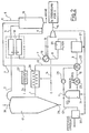
- Fig. 1 das Blockdiagramm einer Anlage zur Erzeugung von Synthesegas zur Verwendung in einem Reduktionsreaktor und
- Fig. 2 das Blockdiagramm der Anlage gemäß Fig. 1 mit zusätzlicher Frischgaserzeugung.
- Wie Fig. 1 zeigt, wird bei dem erfindungsgemäßen Verfahren das in einem Reaktor 16 erzeugte Synthesegas nach einer Gasaufbereitung in einen Reduktionsreaktor 17- geleitet und von dort im Kreislauf wieder dem Reaktor 16 zugeführt.
- Der Synthesegasreaktor 16 wird mit Kohlenstoff in Form von Kohlenstaub beschickt. Der Kohlenstoff kann aber auch in Form von Gas oder öl zugeführt werden. In den Reaktor 16 wird weiterhin auf 400 °C aufgeheizter Sauerstoff und das aus dem Reduktionsreaktor 17 austretende Gas, das in einem Regenerator 18 auf 1.100 °C (max. 1.200 °C) aufgeheizt wird, eingeleitet. Zur Aufheizung des Regenerators 18 dient ein Teil der fühlbaren Wärme des aus dem Reaktor 16 austretenden Synthesegases. Ein für das Verfahren geeigneter Regenerator, der einem heißen Gasstrom Wärme entzieht, speichert und schließlich auf einen anderen Gasstrom überträgt, ist dem Fachmann aus der Hochofen-Technik und Glasherstellung bekannt und braucht nicht besonders beschrieben zu werden.
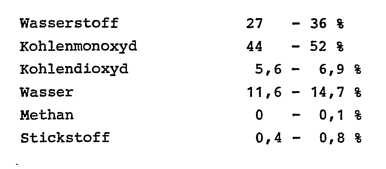
- Im Vergasungsreaktor 16 erfolgt die Umsetzung im Temperaturbereich zwischen 1.300 °C und 1.500 °C. Die bei der Umsetzung anfallende Asche wird unten aus dem Reaktor abgezogen. Den Reaktor 16 verläßt das Synthesegas mit einer Temperatur zwischen 1.200 °C und 1.300 °C und einer Zusammensetzung, wie sie aus Tabelle I, Spalte 6 ersichtlich ist. Nach Durchlaufen des Regenerators 18, aus dem es mit einer mittleren Temperatur von 750 °C austritt, wird das Synthesegas in einem Wärmeaustauscher 19, der mit einem Dampferzeuger gekoppelt ist, auf 300 °C abgekühlt. Der erzeugte Dampf wird mittels eines turbinenangetriebenen Kompressors zur Gewinnung des im Verfahren angesetzten Sauerstoffs verwendet. Uberschußdampf kann zur Eigenbedarfsstromdeckung-eingesetzt werden. Der bei der Sauerstoffgewinnung anfallende Stickstoff wird als Spülgas im Rahmen der Co2-Wäsche des Synthesegases eingesetzt.
- Ein Teil des Synthesegasstromes wird nach Durchlaufen des Wärmeaustauschers 19 abgezweigt und dient zusammen mit zugesetztem Kohlenstaub als Brennmaterial in einem Abgaserhitzer 26. Der Abgaserhitzer 26 heizt das in den Reduktionsreaktor 17 einströmende Gas auf eine Temperatur von ca. 920 °C auf.
- Das nicht im Abgaserhitzer 26 verwendete Gas wird nach Durchlaufen eines Filters 20 oder anderer zur Entfernung von Flugasche geeigneter Vorrichtungsteile einem Hochtemperatur-Konverter 21 zugeführt, mit welchem das günstigste H2/CO-Verhältnis eingestellt werden kann. Die Gaszusammensetzung nach Durchlauf durch den Konverter 21 ergibt sich aus Spalte 9, Tabelle I.
- Das im Hochtemperatur-Konverter 21 aufgeheizte Gas wird vor Eintritt in eine C02JH2S-Wäsche 24 in Wärmeaustauschern 22 und 23 abgekühlt. Der Wärmeaustauscher 23 dient zur Aufheizung von Kesselspeisewasser, das in den Wärmeaustauscher 19 eintritt. Nach der C02/H2S-Wäsche wird das Gas einem Verdichter 25 zugeführt. Der Verdichter 25 speist den Wärmeaustauscher 22, von wo das Gas vorgewärmt dem Abgaserhitzer 26 zugeführt wird. Im Abgaserhitzer 26 wird das Gas, wie bereits beschrieben, aufgeheizt und mit einer Zusammensetzung gemäß Spalte 1, Tabelle I, dem Reduktionsreaktor 17 zugeführt. Die Abgasenergie des Abgaserhitzers 26 reicht aus, um zusätzlich noch den Sauerstoff für den Betrieb des Reaktors (16) in einem Sauerstoff-Vorwärmer 27 aufzuheizen.
- Im Reduktionsreaktor 17, der bei 28 mit Erz beschickt wird und dem bei 29 im Durchlaufverfahren das reduzierte Produkt entnommen wird, erfolgt eine teilweise Oxidation des Reduktionsgases, das den Reaktor 17 mit einer Zusammensetzung gemäß Spalte 2, Tabelle I verläßt. Vom Reduktionsreaktor 17 wird das Gas über die Leitung 2 dem Regenerator 18 zur Aufheizung zugeführt und tritt anschließend mit einer Temperatur von ca. 1.100 °C in den Reaktor 16 ein.
- Zur Temperaturregulierung des aus dem Regenerator (18) austretenden heißen Synthesegases kann kaltes Reduktionsgas aus der Leitung 12 in die Leitung 7 eingespeist werden, wie es in Fig. 1 gestrichelt angedeutet ist.
- Gemäß Fig. 2 wird der beim Verfahren erzeugte überschuß an Synthesegas nach der C02/H2S-Wäsche 24 aus dem Kreislauf ausgeschleust und durchläuft einen Niedertemperatur-Konverter 30 und eine anschließende CO2-Wäsche. In der C02-Wäsche wird, wie schon beschrieben, der bei der Sauerstoffgewinnung anfallende Stickstoff als Spülgas eingesetzt. Das aufbereitete Gas kann als Frischgas z. B. bei der Ammoniak-Erzeugung oder als Heizgas eingesetzt werden.
-

Claims (10)

Applications Claiming Priority (2)
| Application Number | Priority Date | Filing Date | Title |
|---|---|---|---|
| DE19823237334 DE3237334A1 (de) | 1982-10-08 | 1982-10-08 | Verfahren zum betreiben eines reaktors zur erzeugung von synthesegas und vorrichtung zur durchfuehrung des verfahrens |
| DE3237334 | 1982-10-08 |
Publications (3)
| Publication Number | Publication Date |
|---|---|
| EP0108198A2 true EP0108198A2 (de) | 1984-05-16 |
| EP0108198A3 EP0108198A3 (en) | 1987-06-16 |
| EP0108198B1 EP0108198B1 (de) | 1989-06-07 |
Family
ID=6175273
Family Applications (1)
| Application Number | Title | Priority Date | Filing Date |
|---|---|---|---|
| EP83107640A Expired EP0108198B1 (de) | 1982-10-08 | 1983-08-03 | Verfahren zum Betreiben eines Reaktors zur Erzeugung von Synthesegas und Vorrichtung zur Durchführung des Verfahrens |
Country Status (5)
| Country | Link |
|---|---|
| US (1) | US4556421A (de) |
| EP (1) | EP0108198B1 (de) |
| BR (1) | BR8305565A (de) |
| DE (1) | DE3237334A1 (de) |
| ZA (1) | ZA836962B (de) |
Cited By (4)
| Publication number | Priority date | Publication date | Assignee | Title |
|---|---|---|---|---|
| EP0182992A3 (en) * | 1984-10-27 | 1987-01-21 | Man Gutehoffnungshutte Gmbh | Low energy process for producing synthesis gas with a high methane content |
| EP0367428A1 (de) * | 1988-10-15 | 1990-05-09 | The BOC Group plc | Lufttrennung |
| EP0556691A1 (de) * | 1992-02-20 | 1993-08-25 | RUHR OEL GmbH | Verfahren zur Vergasung kohlenstoffhaltiger Rückstände der Mineralölverarbeitung |
| RU2195425C2 (ru) * | 1997-09-05 | 2002-12-27 | Мидрекс Текнолоджиз Инк. | Способ и устройство для ускоренного риформинга топлива с кислородом |
Families Citing this family (2)
| Publication number | Priority date | Publication date | Assignee | Title |
|---|---|---|---|---|
| EP1435253B1 (de) | 2002-12-31 | 2007-01-17 | Abbott Laboratories Vascular Enterprises Limited | Katheter mit einem flexibleren Bereich zwischen Schaft und Spitze sowie Verfahren zu seiner Herstellung |
| KR101220683B1 (ko) * | 2010-12-28 | 2013-01-09 | 주식회사 포스코 | 합성가스를 이용한 환원철 제조장치 및 이를 이용한 환원철 제조방법 |
Family Cites Families (10)
| Publication number | Priority date | Publication date | Assignee | Title |
|---|---|---|---|---|
| US1800856A (en) * | 1926-04-07 | 1931-04-14 | Bradley Linn | Treating iron ore |
| US2113774A (en) * | 1934-11-26 | 1938-04-12 | Schmalfeldt Hans | Process for the gasification of dust or fine-grained fuels with circulating gas |
| DE905974C (de) * | 1951-09-13 | 1954-03-08 | Demag Ag | Verfahren und Vorrichtung zur Herstellung von Gasen mit einem bestimmten Kohlenoxyd-Wasserstoff-Verhaeltnis, insbesondere fuer die Erzreduktion |
| GB799551A (en) * | 1956-02-06 | 1958-08-13 | Texaco Development Corp | Reduction of a metal oxide with carbon monoxide and hydrogen |
| DE2246885C3 (de) * | 1972-09-23 | 1975-08-28 | Thyssen Niederrhein Ag Huetten- Und Walzwerke, 4200 Oberhausen | Anlage zur Reduktion von Eisenerzen im Wege der Direktreduktion |
| US4001010A (en) * | 1974-08-26 | 1977-01-04 | Nippon Steel Corporation | Method for processing reduced iron |
| US4011058A (en) * | 1975-10-01 | 1977-03-08 | Phillips Petroleum Company | Production of substitute natural gas from gasification of coal char |
| DE2908771C2 (de) * | 1979-03-06 | 1984-07-12 | Kraftwerk Union AG, 4330 Mülheim | Kombinierte Anlage zur Vergasung von Kohle und zur Reduktion von Metallerzen |
| GB2078251B (en) * | 1980-06-19 | 1984-02-15 | Gen Electric | System for gasifying coal and reforming gaseous products thereof |
| DE3223702C2 (de) * | 1982-06-25 | 1984-06-28 | M.A.N. Maschinenfabrik Augsburg-Nürnberg AG, 4200 Oberhausen | Verfahren zur Erzeugung von Synthesegas und Reaktor zur Durchführung des Verfahrens |
-
1982
- 1982-10-08 DE DE19823237334 patent/DE3237334A1/de not_active Withdrawn
-
1983
- 1983-08-03 EP EP83107640A patent/EP0108198B1/de not_active Expired
- 1983-09-19 ZA ZA836962A patent/ZA836962B/xx unknown
- 1983-09-28 US US06/536,447 patent/US4556421A/en not_active Expired - Lifetime
- 1983-10-07 BR BR8305565A patent/BR8305565A/pt not_active IP Right Cessation
Cited By (4)
| Publication number | Priority date | Publication date | Assignee | Title |
|---|---|---|---|---|
| EP0182992A3 (en) * | 1984-10-27 | 1987-01-21 | Man Gutehoffnungshutte Gmbh | Low energy process for producing synthesis gas with a high methane content |
| EP0367428A1 (de) * | 1988-10-15 | 1990-05-09 | The BOC Group plc | Lufttrennung |
| EP0556691A1 (de) * | 1992-02-20 | 1993-08-25 | RUHR OEL GmbH | Verfahren zur Vergasung kohlenstoffhaltiger Rückstände der Mineralölverarbeitung |
| RU2195425C2 (ru) * | 1997-09-05 | 2002-12-27 | Мидрекс Текнолоджиз Инк. | Способ и устройство для ускоренного риформинга топлива с кислородом |
Also Published As
| Publication number | Publication date |
|---|---|
| DE3237334A1 (de) | 1984-04-12 |
| BR8305565A (pt) | 1984-05-15 |
| ZA836962B (en) | 1984-05-30 |
| EP0108198A3 (en) | 1987-06-16 |
| US4556421A (en) | 1985-12-03 |
| EP0108198B1 (de) | 1989-06-07 |
Similar Documents
| Publication | Publication Date | Title |
|---|---|---|
| EP0182992B1 (de) | Energiegünstiges Verfahren zur Erzeugung von Synthesegas mit einem hohen Methangehalt | |
| EP2297365B1 (de) | Verfahren und system zur energieoptimierten eisenherstellung mit optimiertem co2-ausstoss | |
| EP0179014B1 (de) | Verfahren zur Herstellung von Roheisen | |
| DE2743830C2 (de) | Verfahren zum Betreiben einer kombinierten Gas-Dampfkraftanlage und Gas-Dampfkraftanlage zur Durchführung des Verfahrens | |
| DE4103362C1 (de) | ||
| DE112005001881T5 (de) | Verfahren und Vorrichtung zum Herstellen von reinen reduzierenden Gasen aus Koksofengas | |
| DE3223702C2 (de) | Verfahren zur Erzeugung von Synthesegas und Reaktor zur Durchführung des Verfahrens | |
| DE3204672A1 (de) | Kombinierter gas-/dampfturbinenprozess | |
| EP0108198B1 (de) | Verfahren zum Betreiben eines Reaktors zur Erzeugung von Synthesegas und Vorrichtung zur Durchführung des Verfahrens | |
| DE102009038323A1 (de) | Verfahren und Vorrichtung zur Verwertung von Biomasse | |
| EP2844849A2 (de) | Verfahren zur nutzung der abgase aus anlagen zur roheisenherstellung für die dampferzeugung | |
| DE2735090C2 (de) | Verfahren zum Reinigen und Kühlen von Wasserstoff und Kohlenoxid enthaltenden Prozeßgasen | |
| EP0016179B1 (de) | Anlage zur Kohlevergasung | |
| DE3404684A1 (de) | Verfahren zur nutzung der beim trockenkuehlen von koks mittels eines gases anfallenden fuehlbaren waerme | |
| DE874297C (de) | Verfahren zur Umsetzung kohlenoxydhaltiger Gasgemische mit Wasserdampf | |
| EP1116862B1 (de) | Verfahren zur Erzeugung von Dampf und eine Dampferzeugeranlage | |
| DE2724833A1 (de) | Kohlevergasung mit kernenergie | |
| DE2701166C2 (de) | "Verfahren und Anlage zum Reinigen des Rohgases eines Festbett-Druckgasgenerators" | |
| EP2650385A1 (de) | Verfahren und Vorrichtung zur Herstellung von flüssigem Roheisen und/oder von Eisenschwamm | |
| DE10012051A1 (de) | Verfahren zur Wärmerückgewinnung bei Hochtemperaturprozessen durch Brenngaserzeugung aus Kohlenwasserstoffen und einem Teilstrom heißer Verbrennungsabgase | |
| CH634345A5 (en) | Process for further use of crude blast furnace gas | |
| DE2724802A1 (de) | Kohlevergasung mit kernenergie | |
| EP2133308A1 (de) | Reingasvorwärmeinrichtung sowie Verfahren zur Reingasvorwärmung | |
| EP0016178B1 (de) | Anlage zur Kohlevergasung | |
| DE19936935C2 (de) | Verfahren und Vorrichtung zur Leistungssteigerung und Brennstoffeinsparung bei der Erzeugung von Roheisen |
Legal Events
| Date | Code | Title | Description |
|---|---|---|---|
| PUAI | Public reference made under article 153(3) epc to a published international application that has entered the european phase |
Free format text: ORIGINAL CODE: 0009012 |
|
| AK | Designated contracting states |
Designated state(s): BE FR GB IT NL |
|
| 17P | Request for examination filed |
Effective date: 19841019 |
|
| RAP1 | Party data changed (applicant data changed or rights of an application transferred) |
Owner name: MAN GUTEHOFFNUNGSHUETTE GMBH |
|
| PUAL | Search report despatched |
Free format text: ORIGINAL CODE: 0009013 |
|
| AK | Designated contracting states |
Kind code of ref document: A3 Designated state(s): BE FR GB IT NL |
|
| 17Q | First examination report despatched |
Effective date: 19880913 |
|
| GRAA | (expected) grant |
Free format text: ORIGINAL CODE: 0009210 |
|
| AK | Designated contracting states |
Kind code of ref document: B1 Designated state(s): BE FR GB IT NL |
|
| ITF | It: translation for a ep patent filed | ||
| GBT | Gb: translation of ep patent filed (gb section 77(6)(a)/1977) | ||
| ET | Fr: translation filed | ||
| PLBE | No opposition filed within time limit |
Free format text: ORIGINAL CODE: 0009261 |
|
| STAA | Information on the status of an ep patent application or granted ep patent |
Free format text: STATUS: NO OPPOSITION FILED WITHIN TIME LIMIT |
|
| 26N | No opposition filed | ||
| ITTA | It: last paid annual fee | ||
| PGFP | Annual fee paid to national office [announced via postgrant information from national office to epo] |
Ref country code: GB Payment date: 19980713 Year of fee payment: 16 |
|
| PGFP | Annual fee paid to national office [announced via postgrant information from national office to epo] |
Ref country code: FR Payment date: 19980720 Year of fee payment: 16 |
|
| PGFP | Annual fee paid to national office [announced via postgrant information from national office to epo] |
Ref country code: BE Payment date: 19980727 Year of fee payment: 16 |
|
| PGFP | Annual fee paid to national office [announced via postgrant information from national office to epo] |
Ref country code: NL Payment date: 19980728 Year of fee payment: 16 |
|
| PG25 | Lapsed in a contracting state [announced via postgrant information from national office to epo] |
Ref country code: GB Free format text: LAPSE BECAUSE OF NON-PAYMENT OF DUE FEES Effective date: 19990803 |
|
| PG25 | Lapsed in a contracting state [announced via postgrant information from national office to epo] |
Ref country code: BE Free format text: LAPSE BECAUSE OF NON-PAYMENT OF DUE FEES Effective date: 19990831 |
|
| BERE | Be: lapsed |
Owner name: MAN GUTEHOFFNUNGSHUTTE G.M.B.H. Effective date: 19990831 |
|
| PG25 | Lapsed in a contracting state [announced via postgrant information from national office to epo] |
Ref country code: NL Free format text: LAPSE BECAUSE OF NON-PAYMENT OF DUE FEES Effective date: 20000301 |
|
| GBPC | Gb: european patent ceased through non-payment of renewal fee |
Effective date: 19990803 |
|
| PG25 | Lapsed in a contracting state [announced via postgrant information from national office to epo] |
Ref country code: FR Free format text: LAPSE BECAUSE OF NON-PAYMENT OF DUE FEES Effective date: 20000428 |
|
| NLV4 | Nl: lapsed or anulled due to non-payment of the annual fee |
Effective date: 20000301 |
|
| REG | Reference to a national code |
Ref country code: FR Ref legal event code: ST |